HAMAR LASER L-705 User manual


WARRANTY
Hamar Laser Instruments, Inc., warrants each instrument and other articles of
equipment manufactured by it to be free from defects in materials and
workmanship under normal use and service, its obligation under this warranty
being limited to making good at its factory any instrument and other article of
equipment which shall within one year after shipment of each instrument and
other article of equipment to the original purchaser be returned intact to Hamar
with transportation prepaid, and which Hamar’s examination shall disclose to
Hamar’s satisfaction to have been thus defective; other than this express
warranty, Hamar neither assumes nor authorizes any other persons to assume for
it any other liability or obligation in connection with the sale of its products.
This warranty is not applicable to instruments or other articles of equipment
manufactured by other companies and limited by a warranty extending for less
than one year. In such an event, the more limited warranty applies to said
instrument or article of equipment.
This warranty shall not apply to any instrument or other article of equipment
which shall have been repaired or altered outside the Hamar factory, nor which
has been subject to misuse, negligence, or use not in accord with instructions
furnished by the manufacturer.
The software described in this manual is furnished under a license agreement
and may be used or copied only in accordance with the terms of the agreement.
It is against the law to copy the software on any medium for any purpose other
than the purchaser's personal use.
The information in this manual is subject to change without notice. No part of
this manual may be reproduced by any means, electronic or mechanical, without
written permission from Hamar Laser Instruments, Inc.
© Copyright Hamar Laser Instruments, Incorporated, 2019
5 Ye Olde Road, Danbury, Connecticut 06810

Table of Contents
Critical Note on Calibration.............................................................................................................1
Introducing the L-705/L-706 Laser Bore Alignment System ..........................................................2
The Laser Bore Alignment System Components.............................................................................4
Model L-705 Laser ......................................................................................................................4
Model L-706 Long Distance Laser...............................................................................................4
Adjusting the Laser ..............................................................................................................5
Attaching the Battery Pack...................................................................................................5
Replacing the Batteries ........................................................................................................6
Pulse/Continuous Modes (L-705 and L-706 Lasers) ...........................................................6
Model A-512 2-Axis Self-Centering Target.................................................................................7
The A-514 A, B and C Self-Centering Laser and Bore Adapters for the A-512 Target ..............8
Bore Diameter Ranges for the A-514 Bore Adapters ..........................................................9
The A-514GS and A-514GL Leg-Setting Gage .........................................................................10
Setting the Legs for the A-514GS (Using Small and Medium Bore Adapters).................10
Setting the Legs for the A-514GL (Using Large Bore Adapters) ......................................11
The T-218 2-Axis See-Through Target/T-225L Large Bore Flange Adapter ............................12
Assembling the T-225L for Use with the T-218................................................................12
The Model R-1307 Readouts .....................................................................................................13
Model R-1307C .................................................................................................................13
Model R-1307-900/2.4 and R-1307-2.4ZB........................................................................13
Model R-1307 Readout -- Control Panel ...........................................................................14
Model R-1307C Readout -- Control Panel ........................................................................15
Configuring the R-1307 or R-1307C for a Local Target ...................................................16
The L-111 Laser Stand and L-102 Laser Beam Translator ........................................................18
How the L-102 Beam Translator Works............................................................................18
How to change the L-111 from a Horizontal Surface to a Vertical Surface ......................19
Bore9 Software ..............................................................................................................................21
Bore Alignment Using the T-218 Target/T-255 Bore Fixture .......................................................22
Laser Buck-In Using the T-218 Target/T-225L Bore Fixture ....................................................22
Bore Alignment Using the A-512 Target/A-514 Bore Adapter.....................................................25
Measuring Bore Alignment ........................................................................................................25
High-Tolerance Bore Alignment................................................................................................25
Measuring Bore Diameters.........................................................................................................25
Bore Alignment Using the L-111/L-102 and A-512/A-514...........................................................26
Two Point Buck-In Procedure....................................................................................................26
Bore Alignment Using the L-111/ L-102/Bore9 ............................................................................31
Bore9 Sample Report .................................................................................................................36
Appendix A – The NORMIN Method (Bore and Spindle)............................................................37
Appendix B – Calculating Bore Diameters....................................................................................39
Appendix C – Remote Buck-in......................................................................................................42
Appendix D – T-218/T-225L Dimensions (Model 3)....................................................................44
Appendix E – T-225L Leg Dimensions/Instructions .....................................................................45
Appendix F – Care and Cleaning of Target Optics........................................................................46

1
Critical Note on Calibration
When configuring the R-1307 Readout, it is critical to match the target ID with the target ID
identified on the serial number of the target. For example, if the target ID on the target serial
number label is 2, then the R-1307 must also be set to the number 2. If the target and readout and
not matched, a centering error of up to .002 in. (0.05 mm) can occur. In addition, the laser switch
setting (CONT. or Fixed vs. PULSE) must also agree with the R-1307 Readout setting. For
CONTinuous (Fixed) Mode, set the readout to F10.10 and for Pulsed Mode, set the R-1307 to
P10.10.
For example: .. or .. for R-1307 #2
For more information on the Pulse/CONTinuous modes on the laser, see Pulse/Continuous Modes (L-
705, L-706 and L-708 Lasers) on Page 6. For complete information on matching the target to the readout,
see Configuring the R-1307 or R-1307C for a Local Target on Page 16.

2
Introducing the L-705/L-706 Laser Bore Alignment System
Bore alignment can be defined as aligning
or checking a bore for straightness or
making a series of bores concentric with
two reference bores. Reference bores are
usually the end bores, but they can be any
two of the series. A laser is placed in an L-
111 stand outside of the series of bores and
the laser beam is adjusted so it passes
through the center of the two reference
bores. This is accomplished by doing what
is referred to as a 2 point buck-in. Once the
laser beam is adjusted to pass through the
two reference bore centers, the remaining
bores can be measured using the same
target for their concentricity to the
reference bores.
Designed for high-accuracy bore
alignments, the L-705/L-706 Laser Bore Alignment System offers the most accurate, yet easy to use laser
alignment systems. With high resolution, capability to measure a wide range of bore diameters, and our
patented self-centering bore adapters, this is the best bore alignment system on the market.
The alignment system also offers a variety of target options, including self-centering, see-through, 2-axis
and 4-axis targets, hand-held readouts, and Windows®-based software to display and analyze alignment
data. The system handles a wide variety of bore alignment applications, including: aluminum can-making
machinery, bar-turning machines, bore straightness checks for cylinders, engine-block crankshaft bore
alignment, stern tube alignment, tail rotor bearing alignment for helicopters, and tube support plate bores
for heat exchangers.
Simplified fixturing and self-centering targets make it possible to set the system up in as little as 15
minutes. Bore straightness data can be taken and analyzed in 30 minutes or less in most cases. This
means even the longest bore application can be measured in just minutes versus hours for optics, tight
wire or other laser systems.
The laser has been designed with a standard aerospace tooling diameter of 2.25 in. (57.15 mm). Since the
laser beam is concentric to the OD to within .0005 in. (0.0127 mm), a simple flat face and .750 in. (19.05
mm) hole on center is all that is needed to hold the laser (powerful magnets hold the laser flush to the
face).
Any bore, from 3.75 in. (92.25 mm) up to 50 in. (1,270 mm) or more, can easily be measured with our
Bore Laser System. The system offers three bore adapters and a leg-setting gage to set the adapters to the
nominal bore ID. For bores from 2.0 in. (50.8 mm) to 3.75 in. (92.3 mm), we offer our A-510 Target and
A-510STA Self-Centering Adapter Hub and M-705CL Customized Measuring Legs.
When used with our R-1307 Readouts and Bore9 Software, the system provides a resolution of .00002 in.
(0.0005 mm). Under good environmental conditions, the laser is accurate to .004 in. (0.1 mm) over the
whole range. By carefully following the NORMIN procedure, (see Appendix A beginning on Page 37)
accuracies of .0003 in. (0.0075 mm) in 10 ft. (3.1 meters) can be achieved.

3
Alignment System Features
•Fast and simple setup
•Built-in horizontal and vertical angular adjustments for quick referencing
•Simple fixturing to mount the laser into the reference bore
•Visible laser beam straight to .0001 in. in 10 ft. (0.0025 mm in 3 m) or .001 in. in 100 ft. (0.025 mm in 30 m)
•R-1307-2.4ZB Readout supports both wireless and cabled targets with a wireless range up to 150 ft. (45 m)
•Self-centering target, accurate to .0003 in. (0.0075 mm) , vastly simplifies measurement process
•System handles a large range of bore IDs from 3.75 in. (92.25 mm) up to 40 in. (1,016 mm)
•Windows®-based Bore9 software with large color graphics to record and analyze bore straightness and
alignment data.
•Dynamic or live display of component misalignment
•Portable enough to fit into small carrying case. Complete system weighs less than 15 lbs. (6.804 kg).
•Laser runs for up to 8 hours on a standard, replaceable 9-volt battery
•Optional A-510SM Small-Bore Target easily accommodates bores as small as 1.5 in. (38.1 mm)
Recommended System Configuration
•L-706 Long Distance Bore Laser
•L-111 Laser Adjustment Stand
•L-102 Axis Laser Beam Translation Fixture
•A-512 2-Axis Bore Target
•A-514A Small-Bore, Self-Centering Adapter for 3.75 in. (95 mm) to 6.75 in. (172 mm) diameter bores
•A-514B Medium-Bore, Self-Centering Adapter for 6.5 in. (165 mm) to 17.5 in. (445 mm) diameter bores
•A-514A Small-Bore, Self-Centering Adapter for 3.5 in. to 6.75 in. diameter bores
•A-514B Medium-Bore, Self-Centering Adapter for 6.5 in. to 17.5 in. diameter bores
•A-514GS Small Leg-Setting Gage for A-514 A and B Adapters
•R-1307B-2.4ZB 2-Axis Combination Readout
•A-814 Shipping Case
Optional Accessories
•A-514C Large-Bore, Self-Centering Adapter for 17.0 in. (432 mm) to 40.0 in. (1 m) diameter bores
•A-514GL Large Let-Setting Gage for A-514 A, B and C Adapters
•A-514CXL X-Large Bore Self-Centering Adapter for 17.0 in. (432 mm) to 50.0 in. (1.3 m) diameter bores
•A-510 2-Axis Bore Target
•A-510STA Self-Centering Adapter Hub
•A-510LTA Self-Centering Adapter Hub for Large Bores
•M-705CL Set of 4 Customized Legs for A-510STA
•
A-510SM Customized, 2-Axis, Small-Bore Target and Adapter
•T-1218 2-Axis Bore Target with 20x20 mm PSD
•T-1220 2-Axis Bore Target with See-Through capability 20x20 mm PSD
•T-1240 2-Axis Self-Centering Bore Target with See-Through capability for Self-Centering Bore
Adapters 20x20 mm PSD
•T-218 2-Axis Universal See-Through Target
•T-225L Large Bore Flange for T-218 Target
•T-231AL 25 ft/ Target Extension Cable
•A-910-2.4ZB Wireless Data Receiver
•S-1403 Bore9 Software

4
The Laser Bore Alignment System Components
Model L-705 Laser
The L-705 Bore Laser is a battery-operated,
visible light laser that mounts magnetically in a
bore fixture or mounting. It is suitable for
almost all bore applications. The laser has two
mounting surfaces: 0.7498 in. (19.04 mm) and
2.2498 in. (57.14 mm). The laser beam is
centered to both mounting ODs to within .0003
in. (0.08 mm). The L-705 laser beam is
designed to shoot up to 110 ft. (33 m) but has
an angular adjustment resolution of .001 in.
(0.025 mm) in 50 ft. (15 m) and is best used
under 50 ft.
Model L-706 Long Distance Laser
For long-distance applications that exceed the
range of the L-705, the L-706 Laser is equipped
with the finer angular adjustments necessary to
set the laser beam to the center of the far
reference target. It is used for applications up to
110 ft. (33 m). The finer angular adjustments
mean there is less adjustment range, which
make the L-706 difficult to use in shorter distances.
The following describes the operational features of the laser. These features include bubble level vial
orientation, micrometer values and settings, ON/OFF switches and the external battery pack.
•The ON/OFF slide switch has a lighted LED to indicate that power is ON.
•The Pulse/Continuous switch selects the laser mode compatible with the readout/interface being
used (see Page 6 for more information about Pulse/Continuous modes and the readouts used for each
mode).
•Battery Pack connector accepts a slip-fit probe with a flexible cord.
•Bubble level vials on the laser mounting flange are used for rotational accuracy. When the bubbles
in the level vial are centered horizontally, all micrometer adjustments (controlling laser beam angle)
will shift the laser beam vertically or horizontally with reference to the bore/target axis. If the
bubbles are not centered, any micrometer adjustment to one laser axis will change the laser beam
position in both axes. The levels also provide fixture mounting repeatability (assuming the laser is
hard-mounted to fixture).
•Micrometer controls are provided for the adjustment of the angle at which the laser beam emerges
from the precision ground, mutually concentric steel laser housing. Each laser has a NOMINAL
setting for both the V-Vertical and the H-Horizontal micrometer controls. The nominal settings are
determined at the factory and correlate to values for the laser beam when it is perpendicular to both
the 2 in. and 4 in. mounting faces. When the bubble in one of the level vials is centered, a nominal
setting of each micrometer squares the laser beam to that specific axis. For example, if the nominal
vertical setting is .120, then setting the micrometer to .120 sets the laser beam square to the vertical
axis. When a laser is mounted in the gearbox or bore adapter, vertical and horizontal micrometers
should be set in the nominal positions to facilitate the alignment and measurement process.
Figure 1 – The L-706 Laser

5
Adjusting the Laser
The laser beam is factory-adjusted to be concentric to the
mounting diameters (2.25 in. or 57.15 mm and .75 in. or 19.05
mm) within ±.0005 in. (.0127 mm). With the adjusting
micrometers set at the nominal position, (see the Nominal
Settings label on the outer flange), the laser beam is perpen-
dicular to the front mounting surface and parallel to the
mounting diameters within ±.0003 in/ft.
In a typical bore measuring application, the laser is mounted
concentric to one end of the bore by means of a fixture ring or
plate. Because fixtures are seldom perfect, the laser beam
requires angular adjustment to make it concentric to the bore.
This is accomplished by placing the self-centering measuring
target at the other end of the bore and adjusting the mi-
crometers on the laser until the laser beam is centered on the
target.
The circular level vial on the laser mounting flange is used to
reference the orientation of the vertical and horizontal axes of
the laser. When the bubble in the level vial is centered, all
micrometer adjustments (controlling laser beam angle) will
shift the laser beam vertically or horizontally with reference
to the bore/target axis. If the circular level bubble is not
centered, any micrometer adjustment to one laser axis will make the laser beam position appear to
change in both axes. The level vial also provides fixture mounting repeatability (assuming the laser is
hard mounted to the fixture). Only minor readjustments of the laser to the bore and fixture surfaces are
required in situations where frequent alignment is expected.
Attaching the Battery Pack
The L-705 Laser battery pack is a stand-alone unit that
attaches magnetically to an extruder gearbox. The
battery pack has a detachable cord with a probe at each
end. One probe attaches directly to a jack on the battery
pack and the other probe is inserted in the control panel
of the L-705 Laser.
1. Turn off the main power switch.
The main power switch must be off before
attaching the battery pack.
2. Insert the probe into the battery power input
jack.
The jack is located on the end panel of the battery
pack. Insert the plug gently until it snaps into
place.
3. Insert the probe into the laser power input jack.
The jack is located on the micrometer control, at
the apex of the Vand H axis arrows. Insert the plug
gently until it snaps into place.
Figure 2–Laser Micrometer Adjustments
Figure 3 – Attaching the Battery Pack

6
Replacing the Batteries
The battery pack uses two 9-volt batteries. The batteries are housed in a two-part case which is held
together by flathead screws. Hamar Laser recommends using alkaline or nickel-cadmium (NiCad) cells
for best performance.
1. Unplug the battery pack from the laser.
Pull the probe out of the laser jack and gently set aside.
2. Unscrew the cover of the battery pack.
Locate and loosen the two captive flathead screws and remove the cover.
3. Replace the two batteries.
Remove the old batteries and replace them with new 9-volt cells, being careful to orient them with
the negative terminal out (or up).
4. Re-attach the cover.
Put the cover back on and secure it to the battery pack with the screws.
Pulse/Continuous Modes (L-705 and L-706 Lasers)
The L-705 and L-706 Lasers are now equipped with a PULSE/CONTinuous switch, which manually
switches the laser beam between Pulsed and Fixed Beam Modes. Pulse Mode automatically removes the
effects of excess (ambient) background light for the R-1307 readouts, providing a more accurate reading.
The R-1307 Readout is capable of supporting both Pulse Mode and Continuous Mode as well as storing
up to nine different target calibration factors for multiple target users. These capabilities must be
specified when ordering a system.
The chart below indicates the operational modes for Readouts/Computer Interfaces that operate with the
L-705/L-706 Lasers:
Mode
Readouts
Computer Interfaces
Pulse
R-1307B-2.4ZB, R-1307BC, R-1307C, R-
1307-900/2.4, R-1307-2.4ZB, R-1307+R
A-910-900/2.4
(when used with R-1307-900 or R-1307-2.4)
A-910-2.4ZB
CONTinuous
R-307, R-307V
R-358
Notes:
1. The T-261A and T-266 Targets do not support the Pulsed-Beam Mode and the system purchased is factory-
configured to operate in CONTinuous mode when using these targets.
2. When using the L-700 Laser with the R-1307 and a 2-Axis Target, the system is factory-configured to operate in
CONTinuous mode.

7
Model A-512 2-Axis Self-Centering Target
The A-512 Target unit is comprised of a target cell, a bore adapter, and
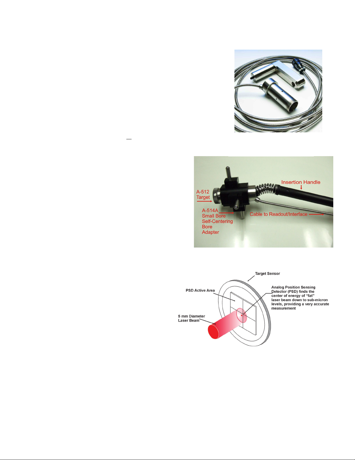
an insertion handle (see Figure 5). The target is inserted into the bore to
sense the position of the laser beam. Laser beam position data is
displayed on a readout. As the bore is adjusted, the readouts display data
in real time.
The target cell is a position-sensitive photo cell surrounded by a
stainless steel housing. When light contacts the photo cell, the
continuous flow of current across the cell is altered. The location of the
contact is recorded as a change in voltage, which the digital readout or
computer interface displays as an offset from the target center. The
effective cell sensitivity range is ± .100 in. (2.5 mm), and changes in
the x and y axis positions of the target can be displayed on a digital
readout to within .0005 in. (0.0127 mm) over 50 ft. (15 m).
The target cell has a milled keyway designed to slipfit
onto a location pin in the bore adapter for self- centering
mode. Four matched and offset (90°) stainless steel legs
serve to center the adapter in the bore. Adapters are
available in many different sizes for use in specialized
bores.
The A-512 2-Axis Bore Target has a 10x10 mm PSD and
is designed specifically for our A-514 line of self-
centering bore adapters. This unique feature allows our
target to be inserted into a bore without any mechanical
setup, such as bore sweeping or the need to rotate the
target to determine mounting errors (a common problem
with most other systems). Insert the target into the bore,
ensure it is oriented at 12:00, and in seconds you have a
measurement. The target is concentric to its
housing to within .0003 in. (0.0075 mm). When
used with the A-514 adapters, the sensor is
centered to the bore within .0006 in. (0.015mm).
Another unique feature of our A-514 adapters is
they can handle a fairly large range of bore
diameter changes of up to .020 in. or 0.5 mm. This
means you don’t need to worry about bore
diameter changes to get accurate measurements.
When using an A-510 Target with the A-510
adapters or the A-512 Target with the A-514A and
A-514B adapters, two types of insertion handles may be
used. One is a solid stainless steel handle intended for
individual bores. The other is a pole for long, continuous
bores such as extruder barrels or gun barrels. The solid
stainless steel handle is designed for the weight of the
handle to firmly lock the target into place. The pole type
is designed with a spring and a universal joint at the rear
of the target, which locks the target into place.
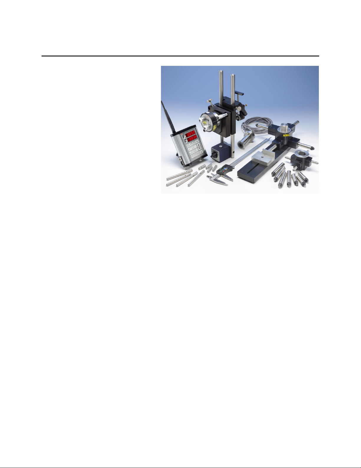
Figure 4 – A-512 2-Axis Self-Centering
Target
The laser is detected, or intercepted, by position-sensing
detectors (PSDs). The center of energy of the laser spot
is detected and converted to an electrical signal
proportional to its location on the surface of the target.
This signal is converted into a calibrated reading, using
a variety of hand-held readouts or computer interfaces
for use with our software.
Figure 5 – A-512 Target with A-514A Small Bore Self-Centering Bore
Adapter

8
The A-514 A, B and C Self-Centering Laser and Bore Adapters for the A-512 Target
Note: The A-514 Adapters are self-centering and therefore cannot be used with the A-512 for measuring
bore diameters.
The A-514 self-centering laser and bore adapters accurately and
quickly position the laser and target on the bore centerline. The
adapters can be centered to the bore to within .0005 in. (0.0127
mm). The adapters have adjustable legs that allow them to be used
for bore diameters ranging from 3.75 in. (95 mm) to 40 in. (1 m)
and the A-514B and A-514C come with counterweights to prevent
the assembled system from tipping.
Three sizes are available, as follows:
•A-514A for bores from 3.75 in. (95 mm) to 6.75 in. (172 mm)
•A-514B for bores from 6.5 in. (165 mm) to 17.5 in. (445 mm)
•A-514C for bores from 17.0 in. (432 mm) to 40.0 in. (1 m)
Note: For bores over one meter, half-bores, or where bore surfaces are worn or rough, the T-218 Two-
Axis Universal Target and T-225L Large Bore Flange are used. The T-218 has a prism that flips out of
the way, allowing the laser beam to pass unobstructed through the target without removing it, which
proves useful for aligning multiple bores over long distances. For half-bores, the T-218 is used with the
A-502A Half-Bore and A-501A Bore Sweep Fixtures.
How the A-512 and A-514 Self-Centering Adapters Work
A-512/A-514 Target & Adapter
Adapter OD = Nominal Bore ID
Bore ID > Nominal ID
Target Tilts Forward
PSD Is Still Centered
Bore ID < Nominal ID
Target Tilts Back
PSD Is Still Centered

9
Bore Diameter Ranges for the A-514 Bore Adapters
Bore Diameter Range
A-514A Bore Adapter
HLI PART
NUMBER
LENGTH ‘L’
BORE DIAMETER RANGE
51403-1
1.22 (30.99 mm)
3.750 – 4.750 (95.25 – 120.65 mm)
51403-2
1.72 (43.69 mm)
4.750 – 5.750 (120.65 – 146.05 mm)
51403-3
2.22 (56.39 mm)
5.750 – 6.750 (146.05-171.45 mm)
Bore Diameter Range
A-514B Bore Adapter
HLI PART
NUMBER
LENGTH ‘L’
BORE DIAMETER RANGE
51414-1
2.60 (60.04 mm)
6.500 – 9.250 (165.1 – 234.95 mm)
51414-2
3.97 (100.84 mm)
9.250 – 12.000 (234.95 – 304.8 mm)
51414-3
5.35 (135.89 mm)
12.000 – 14.750 (304.8 – 374.65 mm)
51414-4
6.72 (170.69 mm)
14.750 – 17.500 (374.65 – 444.5 mm)
Bore Diameter Range
A-514C Bore Adapter
HLI PART
NUMBER
LENGTH ‘L’
BORE DIAMETER RANGE
51425-1
5.50 (139.7 mm)
17.000 – 24.000 (431.8 – 609.6 mm)
51425-2
8.75 (222.2 mm)
23.500 – 30.500 (596.9 – 774.7 mm)
51425-3
12.00 (304.8 mm)
30.000 – 37.000 (762 – 939.8 mm)
51425-4
15.25 (387.4 mm)
36.500 – 43.500 (927.1 – 1104.9 mm)

10
The A-514GS and A-514GL Leg-Setting Gage
The gages are used to set the A-514 Adapter legs to the correct bore
diameter. The gages are available in two sizes, depending on the
size of the bore being measured. The A-514GS is used with the
small (A-514A) or medium (A-514B) bore adapters. The A-514GL
can be used for all three adapters and must be purchased if using the
large bore adapter.
Setting the Legs for the A-514GS (Using Small and
Medium Bore Adapters)
Example: (see Figure 7)
1. To measure a 6 in. bore, each leg must be set to 3 in.
2. Set the caliper to read 3.000 in.
3. Twist the locking nut on the caliper so it does not slide, then
insert the caliper inside the hub on the leg setting fixture.
4. Slide the leg setting gage into position and tighten the bolt
using the Allen wrench provided.
5. Slide the bore adapter over the hub and place the stop pin in the
desired hole.
6. Turn the bore adapter so it’s up against the stop pin and
slide the leg out so it rests against the leg setting ceramic
plate.
7. Tighten the bolts with a 7/64 Allen wrench.
8. Remove the stop pin and turn the bore adapter one more
time, replacing the stop pin. Repeat the process for the next
leg.
9. To set the remaining two legs, the bore adapter must be
removed from the hub and flipped. Secure the legs again
using the same method.
Note: The caliper is used to set the legs to the nominal bore
radius. The accuracy of the caliper’s measurement of the radius
is not important since the bore adapters can handle a small
range of diameter changes (typically ± .010 in. to .025 in.,
depending on the adapter size). The most important part of the
process is to ensure the legs are the same length, which is done
with the Leg Setting Gage. Iif the digital caliper has an error of
.0015 in., as long as the legs are set to the same length using the
Leg Setting Gage, the bore adapter will self-center to .0005 in.
(0.0127 mm) or better.
Figure 7 – Setting the legs for the A-514GS
Figure 6—The A-514GL Leg Setting Gage

11
Setting the Legs for the A-514GL (Using Large Bore Adapters)
The large leg gage can be used for all three bore adapters. When setting the legs for the large bore
adapter you must use the fixture extension.
Example: (see Figure 8)
1. To measure a 30 in. bore, each leg must be set to 15 in.
2. If using the 8 in. fixture extension, insert the extension into the hub and rest the other end in the slot.
3. Set the caliper to 7 in. and press one end of the caliper against the pin of the extension.
4. Slide the leg-setting plate up against the other end of the caliper.
5. After the leg setting fixture has been set to the correct length when using the large bore adapter, slide
the hub spacer on the hub to balance the bore adapter.
6. Slide the large bore adapter over the hub on the spacer and follow the method described in Setting the
Legs for the A-514GS (Using Small and Medium Bore Adapters) on Page 10.
Figure 8 – Setting the legs for the A-514GL

12
The T-218 2-Axis See-Through Target/T-225L Large Bore Flange Adapter
Hamar Laser’s T-218 2-Axis “See-through” target is
designed for multiple-target, bore centering
applications. The T-218 has a prism that flips out of
the way, allowing the laser beam to pass
unobstructed through the target without removing it,
which proves useful for aligning multiple bores over
long distances.
The T-218 Target includes a 10x10 mm PSD
(position sensing device). It can be used with Hamar
Laser’s Bore Alignment Lasers, such as the L-700,
L-705, L-706 and L-708 and is compatible with the
R-1307 series of readouts, Hamar Laser alignment
software and the T-230 Target Stand.
For bores over 1 m, half-bores, or where bore surfaces are worn or rough,
the T-218 Target is used with the T-225L Large Bore Flange.
Assembling the T-225L for Use with the T-218
1. Attach the T-225L Large-Bore Flange Adapter to the T-218 2-Axis
Bore Target using the cap screws provided.
2. Using shoulder screws (5) and spring washers (4), attach the RM-
TGTAC-22504 Measuring Foot to each of the two customer-fabricated
“Jam Rods” (see Appendix D on Page 44). For fabrication
instructions, see Appendix E on Page 45.
3. Screw one Jam Rod assembly into the T-225L at 6:00 and a second
assembly at 9:00, ensuring they are firmly screwed into place with the
measuring feet parallel to each other and perpendicular to the face of the T-218 Target.
4. Screw in the Spring-Loaded Plunger (RM HDWRE-84765A63 – see Note 2 in Appendix D on Page
44) into the third customer-fabricated Jam Rod and attach to the third screw location at 10:30 (see
Appendix D, Note 2 on Page 44).
Figure 9 – T-218 2-Axis See-Through Target
Figure 10 – T-255L Large Bore Flange
with
T-218

13
The Model R-1307 Readouts
As with all of our laser alignment systems, the A-510 and A-
512 Bore Targets provide live alignment data via our R-1307
readouts. This means once the target is installed in a bore
and you are ready to align it, you just watch the readout
continuously update as you adjust the bore, supporting pillow
blocks or bearing sleeves.
The R-1307 Readouts are simple H & V axis readouts that
are extremely easy to use. There is no complicated software
to learn in order to use the system. However, for those who
want to document the alignment and produce a report, there is
no easier bore alignment program to use than our Bore9
software.
To check for bore angle relative to the centerline, just take a
measurement at the front or back of the bore and any
difference shows the angle. Adjust the front and back of the
bore to read zero and it’s aligned. Also, with our unique design,
our target only needs a few inches of bore width to take a
measurement.
Note: Below is a brief description of The Model R-1307C and Model R-
1307-900/2.4 and R-1307-2.4ZB. For detailed information and instructions
for your specific model, please see Hamar Laser’s R-1307 operations
manual.
Model R-1307C
•Supports cabled (local) targets only
•Supports both pulsed-beam and continuous laser modes
•Functional replacement for the R-307 Analog Readout
Model R-1307-900/2.4 and R-1307-2.4ZB
•Supports both wireless targets or cabled (local) targets
•Supports both pulsed-beam and continuous laser modes
•Radio frequency available in either 900 MHz or 2.4 GHz ISM band
•Can also be used as an additional readout to receive data alignment data
transmitted from another R-1307 unit in master (poll) mode.
•The R-1307-2.4ZB can be used with the A-910-2.4ZB Computer Interface
to perform as a wireless readout.
Figure 13 – A-910-2.4ZB Computer Interface
Figure 11 – R-1307 Readouts
Figure 12- R-1307KS Readout Stand

14
Model R-1307 Readout -- Control Panel

15
Model R-1307C Readout -- Control Panel

16
Configuring the R-1307 or R-1307C for a Local Target
Before connecting and configuring a readout, make sure to mount the3 laser and install the target.
Note: Shut off power to the readout before connecting or disconnecting a target from the local port.
1. Connect the cabled target to the local port of the readout, as shown in Figure 14.
Refer to the R-1307 and R-1307C Control Panel drawings for the control panel buttons and indicator
functions applicable to your unit or to the R1307 manual for menu settings and further information.
2. Set the Measurement Units
Press the MENU button until the upper display shows Use the UP and DOWN arrow keys
to select either for inches or for millimeters.
3. Set the Dampening Level
Press the MENU button until the upper display shows . Use the UP and DOWN arrow keys to
set the number of averages. Four (4) is the default setting. Adjust this value as required to suit the
application.
4. Set the Readout Function to Local Target
Press the MENU button until the upper display shows . Use the UP and DOWN arrow keys
to select .
5. Select the PSD descriptor applicable to your target.
Press the MENU button until the upper display shows . Use the UP and DOWN arrow
keys to select the Target Number. Refer to the R-1307 manual for more information regarding PSD
descriptors.
The following is applicable to the R-1307 only:
To make the unit visible to all other radio-enabled devices, you must set the Target Network ID and the
System ID for the readout.
1. Set the Local Target Network ID
Press the MENU button until the upper display shows with the current Target ID ()
blinking. Use the UP and DOWN arrow keys to set the Target ID (the default is 01).
Press the MENU button again until the lower display shows with the current Target ID
() blinking. Use the UP and DOWN arrow keys to set the Target ID to the same value as that of the
upper display’s Target ID (the default is 01).
The upper display will show the vertical (Y) axis position of the local target.
The lower display will show the Horizontal (X) axis position of the local target.
2. Set the System ID (Radio Channel)
Press the MENU button until the upper display shows , with the current System ID ()
blinking. Use the UP and DOWN arrow keys to set the System ID (the default is 01).
Warning!
Targets are matched to specific calibration records in the R-1307 Readouts. For example, Target #1
must be connected to Calibration Record #1 in the R-1307 or the calibration is void. Up to nine
different target calibration records can be stored in each R-1307. When there are multiple calibration
records, the record ID must match the target ID, so if you have Target #1, you should select TGT=01
to select the matching calibration factors.
The R-1307B version of the readouts can only save one target calibration record, so each R-1307B
readout must be matched up the target the calibration factors were generated with.

17
MODEL #T-212
TWO AXIS TARGET (TYPE 1)
VERTICAL
(Y) AXIS
HORIZONTAL
(X) AXIS
ADAPTER CABLE
A
DISPLAY MODE
ZERO
DISPLAY UNITS
B
H
V
TWO AXIS TARGET (TYPE 2)
MODEL #T-212
REQUIRED FOR
TYPE 1 TARGETS
WITH CPC CONNECTOR
CPC CONNECTOR
READOUT, MODEL# R-1307 AND R-1307C
TARGET SENSING
ORIENTATION
(CABLE DOWN)
LOCAL
PORT
(BOTTOM VIEW)
B
DISPLAY MODE
ZERO
DISPLAY UNITS
A
H
V
OPTIONAL SECOND READOUT
MODEL# R-1307 OR R-1307W ONLY
A SECOND READOUT CAN BE USED TO COPY THE
TARGET READING DISPLAYED BY THE READOUT
CONNECTED TO THE TARGET..
CONFIGURE READOUT AS FOLLOWS:
R-1307C:
- SET 'FUNCT' TO LOCAL
'ID' AND 'CH' NOT USED
R-1307:
- SET 'FUNCT' TO LOCAL
- SET 'ID' OF UPPER AND LOWER DISPLAY TO
THE SAME VALUE (DEFAULT=1)
- SET 'CH' TO A VALUE NOT USED BY ANOTHER
READOUT WITHIN RADIO RANGE (DEFAULT=1)
CONFIGURE THIS READOUT AS FOLLOWS:
R-1307 AND R-1307W REQUIRED
- SET 'FUNCT' TO POLL
- SET 'ID' OF UPPER AND LOWER DISPLAY TO
THE SAME VALUES AS THE READOUT THAT
IS CONNECTED TO THE TARGET.
- SET 'CH' TO THE SAME VALUE AS THE READOUT
THAT IS CONNECTED TO THE TARGET
R-1307 WITH A LOCAL TARGET
APPLICABLE TO ALL TWO AXES
CABLED TARGETS, INCLUDING:
T-212
T-214
T-218
A-517
ANTENNA NOT PRESENT IN MODEL# R-1307C
THIS CAPABILITY IS NOT SUPPORTED
BY MODEL#R-1307C
Figure 14 -- Connecting a Local Target to the R-1307
Other manuals for L-705
2
This manual suits for next models
1
Table of contents
Other HAMAR LASER Industrial Equipment manuals