UNIFILLER Mini Dopositor Guide

1
Mini Dopositor
Operation and Spare Parts Manual
MARCH 2013-MINI DOPOSITOR

Unifiller Systems Inc. Page 2 of 48 Manual Part No.: MINI
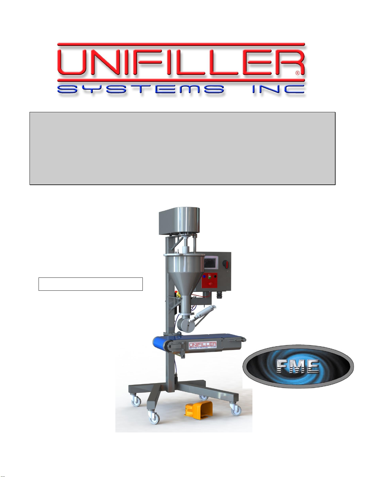
DOPOSITOR
TABLE OF CONTENTS
TABLE OF CONTENTS ......................................................................................................................................................2
INTRODUCTION .................................................................................................................................................................4
IMPORTANT SAFETY INFORMATION.........................................................................................................................5
OVERVIEW...........................................................................................................................................................................7
PRODUCT HANDLING............................................................................................................................................................7
DESIGN FEATURES................................................................................................................................................................7
MACHINE DESCRIPTION AND LAYOUT .....................................................................................................................8
UNPACKING AND INITIAL MACHINE SETUP.............................................................................................................9
POWER REQUIREMENTS ..............................................................................................................................................10
COMPRESSED AIR ...............................................................................................................................................................10
Air Pressure Adjustment................................................................................................................................................10
ELECTRICAL .......................................................................................................................................................................10
PRODUCTION SETUP & OPERATOR ADJUSTMENTS............................................................................................11
PRIMING /PREPARING TO DEPOSIT.....................................................................................................................................11
ADJUSTMENTS....................................................................................................................................................................11
OPERATION: .......................................................................................................................................................................11
CONTROLS LAYOUT.......................................................................................................................................................12
CONTROL BOX LAYOUT .....................................................................................................................................................12
DISASSEMBLY AND CLEANING...................................................................................................................................13
EMPTY PRODUCT FROM MACHINE......................................................................................................................................13
CLEANING ..........................................................................................................................................................................13
INSPECTION AND REASSEMBLY ..........................................................................................................................................14
CONVEYOR BELT TRACKING AND TIGHTENING..................................................................................................................14
SCREEN HIERARCHY...........................................................................................................................................................15
SCREEN HIERARCHY (CONT’D) ..........................................................................................................................................16
SCREEN HIERARCHY (CONT’D) ..........................................................................................................................................17
CONTROL SYSTEM DESCRIPTION.............................................................................................................................18
HELP SCREENS ...................................................................................................................................................................18
MAIN STARTUP SCREEN .....................................................................................................................................................19
MAIN STARTUP SCREEN CONTINUED….............................................................................................................................20
MINI DOPOSITOR SCREEN...................................................................................................................................................21
MINI DOPOSITOR MANUAL SCREEN ...................................................................................................................................22
STATISTICS SCREEN............................................................................................................................................................23
LOAD RECIPE SCREEN ........................................................................................................................................................24
SAVE RECIPE SCREEN.........................................................................................................................................................25
MODE SCREEN....................................................................................................................................................................26
CLEAN SCREEN...................................................................................................................................................................27
LOGIN SCREEN ...................................................................................................................................................................28
SYSTEM SCREEN.................................................................................................................................................................29
TECHNICAL SCREEN ...........................................................................................................................................................30

Unifiller Systems Inc. Page 3 of 48 Manual Part No.: MINI
DOPOSITOR
TECHNICAL 2SCREEN ........................................................................................................................................................31
NEW PASSWORD SCREEN ...................................................................................................................................................32
DIAGNOSTICS WARNING SCREEN .......................................................................................................................................33
DIAGNOSTICS OUTPUTS SCREENS.......................................................................................................................................34
DIAGNOSTICS ANALOG OUTPUTS SCREEN..........................................................................................................................35
DIAGNOSTICS INPUTS SCREEN............................................................................................................................................36
ALARMS AND DIAGNOSTICS ...............................................................................................................................................37
ALARMS AND DIAGNOSTICS CONTINUED ...........................................................................................................................38
TROUBLESHOOTING GUIDE........................................................................................................................................39
PREVENTATIVE MAINTENANCE................................................................................................................................40
ROUTINE MAINTENANCE....................................................................................................................................................40
General..........................................................................................................................................................................40
Daily..............................................................................................................................................................................................40
Weekly ..........................................................................................................................................................................................40
3 Monthly......................................................................................................................................................................................40
SPARE PARTS KIT............................................................................................................................................................41
SUGGESTED ADDITIONAL SPARE PARTS................................................................................................................41
SPARE PARTS LIST –MINI DOPOSITOR....................................................................................................................42
PNEUMATIC PARTS.........................................................................................................................................................42
ELECTRICAL PARTS.......................................................................................................................................................43
ELECTRICAL PARTS.......................................................................................................................................................44
MASTER ASSEMBLY EXPLODED VIEW:...................................................................................................................45
ROTARY VALVE ASSEMBLY........................................................................................................................................46
MINI DOPOSITOR PNEUMATIC SCHEMATIC ......................................................................................................47
CONTROL PANEL LAYOUT...........................................................................................................................................48

Unifiller Systems Inc. Page 4 of 48 Manual Part No.: MINI
DOPOSITOR
INTRODUCTION
Thank you for purchasing FME Equipment from Unifiller Systems Inc. We strive to manufacture the
world's best bakery equipment, using the latest technology and components available. We are sure you
will get years of trouble free use, and excellent productivity from your new investment.
Please take a few minutes to read this manual and familiarize yourself with the layout of the controls,
and the set up and operating procedure.
Please do not hesitate to contact us if you have any questions regarding the setting up or operation of
your new Mini Dopositor. You can contact us from 7.00 a.m. to 4.00 p.m. Pacific standard time at the
following numbers:
Factory Contact Information
Telephone
Telephone (Main): (604) 272-1233
Telephone (Toll Free): (888) 733-8444
Fax: (604) 677-5844
Parts & Service –direct (877) 272-1233
Address
Unifiller Systems Inc.
7621 MacDonald Road
Riverpointe Business Park
Delta, B.C. V4G 1N3
FME Food Machinery Engineering Ltd
#8 19158 94th Ave
Surrey, BC V4N 4X8

Unifiller Systems Inc. Page 5 of 48 Manual Part No.: MINI
DOPOSITOR
IMPORTANT SAFETY INFORMATION
These safety instructions must be read prior to operating, sanitizing
or servicing the equipment.
All machines have a risk of personal injury wherever moving parts are involved in
their operation. Unifiller Systems has taken all possible precautions to reduce and
wherever possible eliminate the dangers associated with moving parts. All users
must read and abide by the instructions in this manual will further reduce the risk
of any personal injury. All personnel that will operate, maintain & sanitize must
read and fully understand all aspects of safety of this machine.
All users must familiarize themselves with the warning decals distributed
around the machinery, (see following list for examples & definitions).
Operators must have been trained, either in person, video demonstration or
having read manual prior to operating machinery. They must also understand
and follow safety procedures as noted in training materials.
Turn off and lock out main electrical power and pneumatic disconnect sources
from equipment prior to attempting to clean, dismantle or make any manual
adjustments to machine or adjust speed of equipment.
Always isolate and bleed pressure from air supply prior to disconnecting air
lines.
Operators should be familiar with all automated motions of machinery, no
reaching or placement of hands within the utilized space at any time machine is
operating.
Operator must ensure that dress attire is appropriate, secure all loose clothing,
or hair and remove or cover any personal jewelry.
Stand clear of the machine when opening and lowering the hopper.
Do not run product or water, with temperatures exceeding 140°F (60°C),
through the machine.

Unifiller Systems Inc. Page 6 of 48 Manual Part No.: MINI
DOPOSITOR
Always wash out the machine after use, dismantle and lubricate all the seals (As
per cleaning instructions in this manual).
Safety guards or devices must not be removed or disabled by any personal
other than when locked out for service maintenance by a technician.
Operators to daily pre-check functional operation of the EMERGENCY STOP
button at all locations around equipment.
Warning Shock Hazard - always connect this machine to a grounded power
source.
Operators must not leave their workplace while machinery is still running.
Control boxes are not to be opened, or washed with high pressure hose directed
at operator controls or control enclosures.
Conveyor tracking, or major operating adjustments, must be performed by a
supervisor or other qualified trained personal.
Caution the air lines on this machine are under very high pressure, severe
injury could result if tampering or adjustments are made by non-qualified
personal.
Stop machinery and report any unusual, noisy, or erratic operation of
equipment to your supervisor.
IMPORTANT:
All Stainless Steel parts are coated with a protective coating at the factory and
therefore any Stainless Steel parts that may come into contact with product must first
be washed in hot water and detergent.

Unifiller Systems Inc. Page 7 of 48 Manual Part No.: MINI
DOPOSITOR
Overview
The Unifiller Mini Dopositor is the modern solution for your dough depositing and extruding needs. It
is designed to provide maximum efficiency and safety through our robust and strong design.
The Mini Dopositor is built to be used with a wide range of products such as cookies, bars and brownie
dough. It can also be customized to run products that conventional machines could never run.
The feed auger is specially designed to be gentle on your product. It is fully accessible for ease of
cleaning and removal of allergens.
Product Handling
Cuts through inclusions - BIG CHUNKS!
Produce up to 60 cuts per minute (3600 deposits per hour).
Accurate portion Control
No Heat is transferred from specially designed auger- no smearing.
Multiple form shapes available
Design Features
Easy to clean open design for complete sanitation and allergen removal.
User friendly control interface.
Hopper capacity 35 lbs (15.5kg).
Easy to set up and disassemble for cleaning-only 4 parts to clean
Foot pedal deposit switch.

Unifiller Systems Inc. Page 8 of 48 Manual Part No.: MINI
DOPOSITOR
MACHINE DESCRIPTION AND LAYOUT
The Mini Dopositor is designed to deposit Cookies, Bars and Brownies onto the conveyor belt or onto
sheet pans. The length, width, thickness and number of deposits can be customized to provide a wide
variety of configurations depending of the product requirements.
Removable hopper
and auger design
for ease of cleaning
and allergen
removal.
Control Panel
with PLC,
Touch Screen
and Operator
Controls
Conveyor
with Motion
Control

Unifiller Systems Inc. Page 9 of 48 Manual Part No.: MINI
DOPOSITOR
UNPACKING AND INITIAL MACHINE SETUP
Once the machine is received following shipping, inspect for damage. Carefully remove all packaging
and shipping materials from the machine and its parts, place the spare parts in a safe storage area close
by the machine for easy access.
IMPORTANT:
All Stainless Steel parts are coated with a protective coating at the factory and therefore any Stainless
Steel parts that may come into contact with product must first be washed in hot water and detergent.
NOTE:
Before filling the hopper, ensure that the machine is assembled correctly with safety guard in place.

Unifiller Systems Inc. Page 10 of 48 Manual Part No.: MINI
DOPOSITOR
POWER REQUIREMENTS
Compressed Air
Minimum Compressed Air Requirements: 4 cfm @ 80 PSI. (5.5 Bar)
Typical compressor requirements: Minimum 2 horse power, capable of 4
C.F.M. @ 100 P.S.I. (7 Bar). 5 HP is the ideal size, as it will last many
years longer than a smaller unit.
Connect the main air supply hose (minimum 3/8” inside diameter) from
your compressor and air dryer (not supplied) to the UNIFILLER male
quick connector that is located just below the machines Air regulator /
Water filter.
Note: Female quick disconnect fitting (Unifiller Pt #1120).
Air Pressure Adjustment
To adjust the machine air pressure:
Pull UP the black air regulator adjustment cap/knob on the top of the
regulator assembly
- Turn CLOCKWISE to increase air pressure.
- Turn COUNTER CLOCKWISE to decrease- the air pressure.
Recommended Settings:
Adjust the air pressure as follows:
Machine at Rest - Adjust to: 80 P.S.I. (6 Bar)
Machine Cycling –Adjust to 70 P.S.I. (5 Bar) minimum
After the air pressure is set, depress the top cap to lock the setting.
Important:
The compressed air supplied to the Mini Dopositor must be filtered and dried prior to connection to
the machine. Failure to comply will result in damage to the machine and the warranty will become
void.
Electrical
Minimum Electrical Connection Requirements:
System Voltage: 208 - 230 VAC 60 HZ, Single Phase
Current: 15 Amps

Unifiller Systems Inc. Page 11 of 48 Manual Part No.: MINI
DOPOSITOR
PRODUCTION SETUP & OPERATOR ADJUSTMENTS
The main components of the Mini Dopositor module are the foot pedal, auger and rotary valve. These
can be adjusted to handle different products and patterns of depositing
Priming / Preparing to Deposit
Priming is the procedure used to fill the depositing die/chamber with product mix as well as to remove all air
pockets from within the empty machine.
1. Fill the hopper with small blocks (the size of a hand full) of dough.
2. Turn the air supply and electrical power to the machine on.
3. Start the Mini Dopositor and run in continuous mode until dough is consistently extruding from the die
port.
4. Observe dough level while priming. Addition of more dough may be required so as to prevent air
pockets from forming and restricting the dough from entraining into the auger.
Adjustments
1. Set your desired cut rate to accommodate your production demands, up to 60 cuts per min
2. To regulate the deposit weight, first adjust the auger speed to achieve desired weights. Increasing the
auger speed will force more dough thru making heavier deposits and decreasing the auger speed will
reduce the amount of dough therefore reducing the deposit weight.
3. If targets are not achieved thru adjusting the auger speed, adjust the cut rate accordingly. Lowering the
cut rate will increase the weight of the deposit whereas increasing the cut rate will decrease the deposit
weight.
4. Once the appropriate parameters have been set to achieve the desired deposit weights, the combination
can be saved as a recipe specific to that type of dough.
Operation:
1. When in continuous mode, one push of the foot pedal will start the Mini Dopositor and commence the
conveyor belt and the selected cutting cycle. When you depress the foot pedal a second time it will
cease the cutting cycle.
2. When in Foot Pedal mode, each depression of the foot pedal will create a deposit. Conveyor belt will
continue to move but there will be no deposits unless the foot pedal is depressed.
.

Unifiller Systems Inc. Page 12 of 48 Manual Part No.: MINI
DOPOSITOR
CONTROLS LAYOUT
This machine is equipped with an HMI operator touch screen mounted inside a NEMA 4X
enclosure. Most operator adjustments can be made from the touch screen.
Control Box Layout
See Operating Instructions for details
The Operator Control Panel includes the following controls:
Item
Function
Power Switch
To power up or shut down the machine.
Power Light
Lit when power is connected and turned on.
Operator Screen
Touch screen to adjust parameters, recall and save Recipes.
Start / Stop pushbuttons
with Run Light
To start or stop the machine.
Green Run light shows when the machine is in operation.
Auger Reverse Pushbutton
This button can be used to jog the auger in reverse to remove
product prior to cleaning.
Emergency Stop
To stop the machine immediately.
Unitronics
Operator Screen
Start/Stop
Buttons with Run
Light
Power Switch
with Lockout
Capability
Power Light
Emergency Stop
Button
Auger Reverse
Pushbutton

Unifiller Systems Inc. Page 13 of 48 Manual Part No.: MINI
DOPOSITOR
DISASSEMBLY AND CLEANING
Empty Product from Machine
1. Run the Mini Dopositor until the contents of hopper are empty.
2. Turn power switch to OFF.
3. Turn the air supply OFF.
Cleaning
Safety –Always follow appropriate lock out procedure prior to performing any cleaning or
maintenance on Mini Dopositor.
FOR CLEANING PURPOSES DO NOT USE ANY STRONG ALKALIS (BASE) SUCH AS
CAUSTIC SODA OR SODIUM HYDROXIDE NOR ANY ACIDS AS THIS WILL DAMAGE THE
ELECTRICAL, AIR AND MECHANICAL COMPONENTS, AS WELL AS THE FINISHES ON
THE METALS.
1. Turn power switch to OFF.
2. Turn the air supply OFF.
3. Remove the rotary valve by disconnecting the quick connect hose fittings. Remove the tri clamp
which holds the rotary valve to the hopper
4. Remove any leftover dough from the hopper outfeed section.
5. Disconnect the auger shaft from the motor shaft by raising the coupling guard and unlatching the
coupling. Turn coupling 90degrees to keep coupling disengaged. Remove the hopper and auger by
unlatching the toggle clamps from the frame. Separate auger from hopper prior to cleaning.
6. The entire machine can be washed down, but do not spray high pressure water directly onto the
touch screen and electronic components.

Unifiller Systems Inc. Page 14 of 48 Manual Part No.: MINI
DOPOSITOR
Inspection and Reassembly
1. Place auger into hopper prior to reassembly.
2. Reattach hopper to frame by aligning and latching the 2 toggle clamps
3. Align and re-attach the auger shaft to the motor shaft and slide coupling into place.
4. Place die into proper position prior to attaching safety guard to hopper. Slide Safety guard with
cutting mechanism attached back into alignment with the hopper outfeed.
5. Replace and secure the triclamp around the hopper outfeed.
Note:
If you need assistance on troubleshooting your machine, please copy and fill out the Unifiller
Diagnostic Record Log at the end of this manual before contacting Unifiller whenever possible.
Conveyor Belt Tracking and
Tightening
The Conveyor belt is designed to run in the
center of the conveyor bed.
If the belt moves excessively to one side, turn
the nut to tighten the “high” side to steer the
belt back to center.
If the conveyor belt is slipping, tighten both nuts to increase the tension of the conveyor belt.
CAUTION:
Do not tension belt excessively as it will cause premature failure of the motorized pulley and idler
pulley.
Always ensure there is no moisture between the belt and conveyor bed as this will produce a wet
bond of the belt to the bed. This will prevent movement of the belt and lead to premature wearing.
Proper and safe belt tension is achieved when the belt slips on the drive pulley when the belt is
pressed firmly onto the conveyor bed.

Unifiller Systems Inc. Page 15 of 48 Manual Part No.: MINI
DOPOSITOR
Screen Hierarchy

Unifiller Systems Inc. Page 16 of 48 Manual Part No.: MINI
DOPOSITOR
Screen Hierarchy (Cont’d)

Unifiller Systems Inc. Page 17 of 48 Manual Part No.: MINI
DOPOSITOR
Screen Hierarchy (Cont’d)

Unifiller Systems Inc. Page 18 of 48 Manual Part No.: MINI
DOPOSITOR
CONTROL SYSTEM DESCRIPTION
Help Screens
Help Screens are accessed by touching any parameter name.
These screens allow the operator to get a brief explanation for the
parameter they wish to view/edit. This is usually used as a
reminder of what the parameter does without having to refer to this
user manual.
This user manual must be read first before operating the machine
and the Help Screens should not supplement the manual.
Note: Most parameters names (in white text) will link to a Help
Screen.
The Help Screens contain the following functions and displays:
Item
Function
BACK Button
This button returns to the previous screen.

Unifiller Systems Inc. Page 19 of 48 Manual Part No.: MINI
DOPOSITOR
Main Startup Screen
The Main Startup screen is the primary operator screen and is
shown when the machine is first powered up.
The Main Startup screen contains the following functions and displays:
Item
Function
CURRENT ACCESS LEVEL
Displays the security access level which is currently logged in.
RECIPE
Displays the recipe number and recipe name that is currently loaded.
ACTUAL PRODUCTION
RATE
Displays how many cuts the machine is doing per minute at the
current rate.
This may be different than the set production rate because the line
may have to wait for certain delays.
SHIFT CYCLES
Displays the current count of cuts that have been done since the last
reset. This count can be reset using the Reset Shift Cycles button on
the Statistics screen.
DOPOSITOR Button
Accesses the Dopositor parameter screen which allows the operator
to: change parameters which affect the function of the Dopositor, and
cycle the Dopositor functions manually.
STATISTICS Button
Accesses the Statistics screen which allows the operator to view: the
Actual Production Rate, Actual Cycle Time, Runtime hours, Total
Cycles, and Shift Cycles.
The Statistics screen also shows the status of critical sensors as well
as Trial Mode Cycles Left if Trial Mode is enabled.
The Statistics screen also allows the operator to reset the Shift
Cycles counter.
Continued on the next page…

Unifiller Systems Inc. Page 20 of 48 Manual Part No.: MINI
DOPOSITOR
Main Startup Screen Continued…
The Main Startup screen is the primary operator screen and is
shown when the machine is first powered up.
These are more features of the Main Startup screen which were
not mentioned on the previous page.
The Main Startup screen also contains the following functions and displays:
Item
Function
RECIPE Button
Accesses the Load Recipe screen which allows the operator to load a
recipe when the machine is not running.
It also gives access to the Save Recipe screen.
This screen is described further on in this document.
SYSTEM Button
Accesses the System screen which allows the operator to: change
parameters that affect how the machine runs, and access to the
technical screen.
This screen is described further on in this document.
MODE Button
Accesses the Mode screen which allows the operator to change
machine modes and to turn on/off Test Mode for machine endurance
testing and Washdown Mode for cleaning.
This screen is described further on in this document.
CLEAN SCREEN Button
Accesses the Clean screen which is empty and allows the operator to
wipe the screen without accidentally changing machine settings.
This screen is described further on in this document.
LOGIN / LOGOUT BUTTON
Accesses the Login screen allows the operator to enter a password
for a higher security level. These levels include: Operator,
Supervisor, Technical, and Factory.
A higher security level has access to more features as well as all of
the features lower levels have access to. These security levels are
mentioned if they are required for certain screens.
This screen is described further on in this document.
If a user is currently logged in, the button will show LOGOUT and can
be pressed to logout any higher security level back to the Operator
level.
Table of contents
Other UNIFILLER Industrial Equipment manuals