Speck pumpen BADU Quick 1 User manual
Montage- und Betriebsanleitung
Installation and operation manual
BADU
®
QUICK
10/07
VG 766.2400.050 1' 10/07 D/GB - BA
D
GB


1
INHALTSVERZEICHNIS
1. Allgemeines ..............................................................................................2
General.....................................................................................................9
2. Sicherheit..................................................................................................4
Safety......................................................................................................11
3. Transport und Zwischenlagerung .............................................................6
Transportation and Intermediate Storage...............................................13
4. Beschreibung............................................................................................6
Description..............................................................................................13
5. Aufstellung / Einbau.................................................................................6
Placement / Installation...........................................................................13
6. Inbetriebnahme.........................................................................................7
Start-up...................................................................................................14
7. Wartung / Instandhaltung.........................................................................7
Maintenance ...........................................................................................14
8. Störungen .................................................................................................8
Malfunctions............................................................................................15

2
Montage- und Betriebsanleitung für
BADU®QUICK Kerzenfilter
1. Allgemeines
Speck Pumpen Verkaufsgesellschaft Karl Speck GmbH & Co. KG, Neunkirchen a. Sand
Kerzenfilter BADU QUICK
Ursprungsland: Bundesrepublik Deutschland
Einsatzbereich:
Der BADU QUICK Kerzenfilter ist ausschließlich zur Filterung des Schwimm-
badwassers in Verbindung mit einer Schwimmbadpumpe einzusetzen.
Für andere Einsätze oder Zweckentfremdung ohne unsere Freigabe über-
nimmt der Hersteller keinerlei Haftung!
Der BADU QUICK ist für kleine Schwimmbecken, Hot-Whirl-Pools, Sauna-
tauchbecken und Springbrunnen entwickelt worden.
Keinesfalls eingesetzt werden dürfen diese Kerzenfilter für:
– brennbare Flüssigkeiten
– leicht flüchtige Flüssigkeiten
– giftige Flüssigkeiten
– aggressive Flüssigkeiten
Maximale Einsatztemperatur: 60°C
Maximaler Gehäuseinnendruck: 2,5 bar
Technische Daten BADU®QUICK Typ 1 Typ 2 Typ 4
Förderstrom (m3/h) mit BADU®90/7 4,50 6,50 8,50
Förderstrom (m3/h) mit BADU®FA 42/6 4,00 6,00 8,00
Anzahl der Filterkerzen (Feinheit ca. 50 µm) 1 2 4
Filterfläche (m2) 0,60 1,20 2,40
Eingang R 11/2R 11/2R 11/2
Ausgang R 11/2R 11/2R 11/2
Gewicht (kg) 1,5 3,5 4,5
D

3
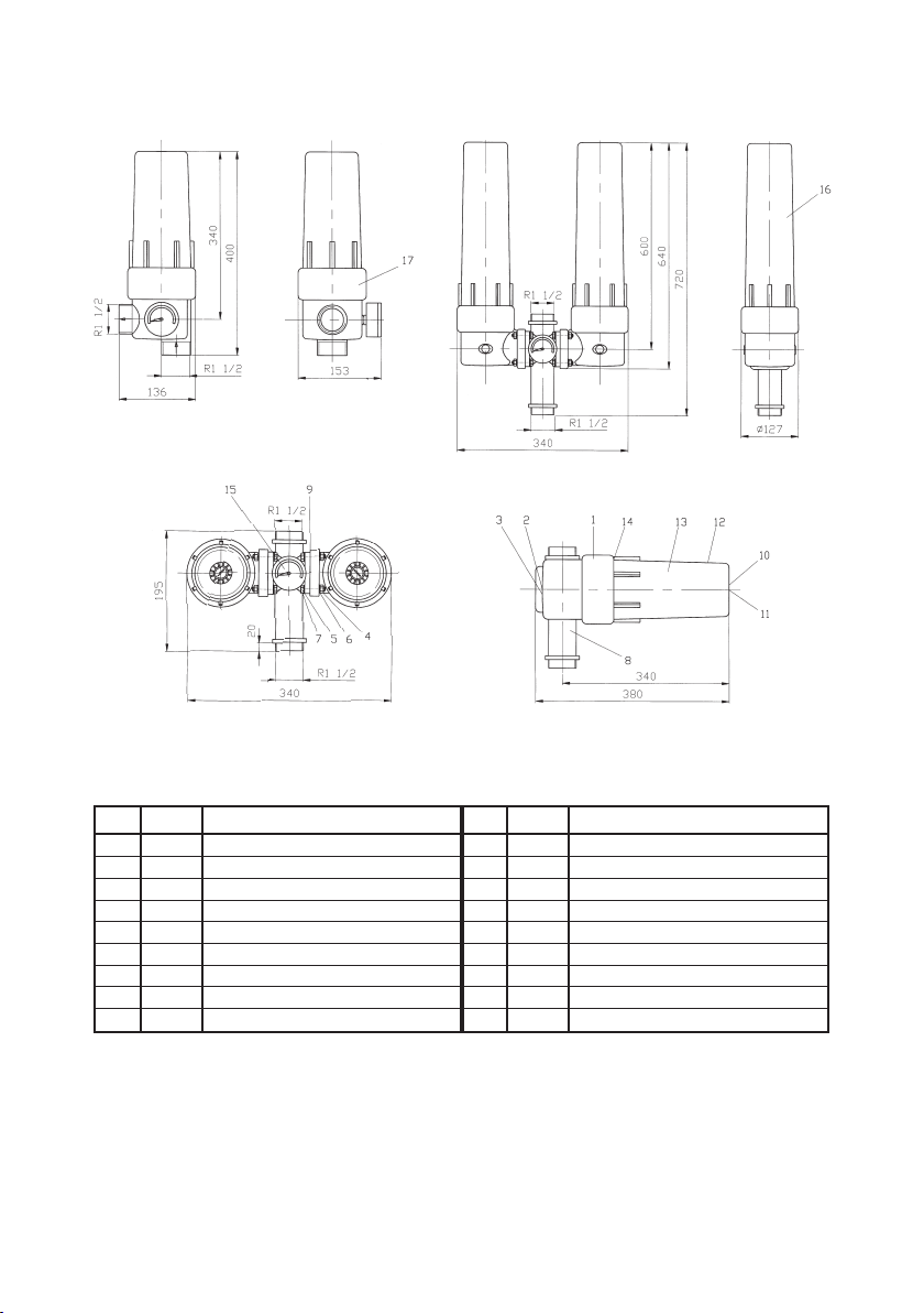
Zeichnungen für Typ 1/2/4
Pos. Anzahl Benennung
1 2 Oberteil für Typ 2 und 4
2 2 Entlüftungsstopfen Messing
3 2 O-Ring 11,5 x 2,4
4 8 Sechskantmutter A2 M6
5 8 Beilagscheibe A2 M6
6 8 Federring A2 M6
7 8 Sechskantschraube A2 M6 x 25
8 1 Gehäuse Kunststoff
R11/2
AG
9 2 Gehäusedichtung
Pos. Anzahl Benennung
10 2 O-Ring 11,5 x 2,4
11 2 Entleerungsstopfen Messing
12 1/2 Unterteil für Typ 1 und 2
13 2 Filterkerze
14 2 Quad. Ring 94,6 x 6,33
15 1 Manometer
16 2 Unterteil lang für Typ 4
17 1 Oberteil für Typ 1
1 Schlüssel
Technische Änderungen vorbehalten.
Typ 1
Typ 4
Typ 2
Ersatzteilliste
BADU
®
QUICK
Kundendienst, Reparaturservice und Ersatzteile
Telefon 0 9123 - 949-700
Telefax 0 9123 - 949-245
E-mail [email protected]
4
2. Sicherheit
Diese Betriebsanleitung enthält grundlegende Hinweise, die bei Aufstellung,
Betrieb und Wartung zu beachten sind. Daher ist diese Betriebsanleitung unbe-
dingt vor Montage und Inbetriebnahme vom Monteur sowie dem zuständigen
Fachpersonal / Betreiber zu lesen und muss ständig am Einsatzort der
Maschine /Anlage verfügbar sein.
Es sind nicht nur die unter diesem Hauptpunkt Sicherheit aufgeführten allge-
meinen Sicherheitshinweise zu beachten, sondern auch die unter den anderen
Hauptpunkten eingefügten speziellen Sicherheitshinweise, so. z.B. für den pri-
vaten Gebrauch.
2.1 Kennzeichnung von Hinweisen in der Betriebsanleitung
Die in dieser Betriebsanleitung enthaltenen Sicherheitshinweise, die bei Nicht-
beachtung Gefährdungen für Personen hervorrufen können, sind mit dem allge-
meinen Gefahrensymbol
Sicherheitszeichen nach DIN 4844 - W 9
bei Warnung vor elektrischer Spannung mit
Sicherheitszeichen nach DIN 4844 - W 8
besonders gekennzeichnet.
Bei Sicherheitshinweisen, deren Nichtbeachtung Gefahren für die Maschine
und deren Funktionen hervorrufen kann, ist das Wort
eingefügt.
Direkt an der Maschine angebrachte Hinweise wie z.B.
– Drehrichtungspfeil
– Kennzeichen für Fluidanschlüsse
müssen unbedingt beachtet und in vollständig lesbarem Zustand gehalten wer-
den.
2.2 Personalqualifikation und -schulung
Das Personal für Bedienung, Wartung, Inspektion und Montage muss die ent-
sprechende Qualifikation für diese Arbeiten aufweisen. Verantwortungsbereich,
Zuständigkeit und die Überwachung des Personals müssen durch den Betrei-
ACHTUNG

5
ber genau geregelt sein. Liegen bei dem Personal nicht die notwendigen
Kenntnisse vor, so ist dieses zu schulen und zu unterweisen. Dies kann, falls
erforderlich, im Auftrag des Betreibers der Maschine durch den Hersteller / Lie-
ferer erfolgen. Weiterhin ist durch den Betreiber sicherzustellen, dass der Inhalt
der Betriebsanleitung durch das Personal voll verstanden wird.
2.3 Gefahren bei Nichtbeachtung der Sicherheitshinweise
Die Nichtbeachtung der Sicherheitshinweise kann sowohl eine Gefährdung für
Personen als auch für Umwelt und Maschine zur Folge haben. Die Nichtbeach-
tung der Sicherheitshinweise kann zum Verlust jeglicher Schadenersatzansprü-
che führen.
Im einzelnen kann Nichtbeachtung beispielsweise folgende Gefährdungen
nach sich ziehen:
– Versagen wichtiger Funktionen der Maschine /Anlage
– Versagen vorgeschriebener Methoden zur Wartung und Instandhaltung
– Gefährdung von Personen durch elektrische, mechanische und chemische
Einwirkungen
– Gefährdungen der Umwelt durch Leckage von gefährlichen Stoffen
– Beschädigung von Einrichtungen und Bauwerken
2.4 Sicherheitsbewusstes Arbeiten
Die in dieser Betriebsanleitung aufgeführten Sicherheitshinweise, die bestehen-
den nationalen Vorschriften zur Unfallverhütung sowie eventuelle interne Ar-
beits-, Betriebs- und Sicherheitsvorschriften des Betreibers sind zu beachten.
2.5 Sicherheitshinweise für den Betreiber / Bediener
Führen heiße oder kalte Maschinenteile zu Gefahren, müssen diese Teile bau-
seitig gegen Berührung gesichert sein.
Berührungsschutz für sich bewegende Teile (z.B. Kupplung) darf bei sich in Be-
trieb befindlicher Maschine nicht entfernt werden.
Leckagen (z.B. der Wellendichtung) gefährlicher Fördergüter (z.B. explosiv, gif-
tig, heiß) müssen so abgeführt werden, dass keine Gefährdung für Personen
und die Umwelt entsteht. Gesetzliche Bestimmungen sind einzuhalten.
Gefährdungen durch elektrische Energie sind auszuschließen (Einzelheiten
hierzu siehe z.B. in den Vorschriften des VDE und der örtlichen Energieversor-
gungsunternehmen).
2.6 Sicherheitshinweise für Wartungs-, Inspektions- und Montagearbeiten
Der Betreiber hat dafür zu sorgen, dass alle Wartungs-, Inspektions- und Mon-
tagearbeiten von autorisiertem und qualifiziertem Fachpersonal ausgeführt wer-
den, das sich durch eingehendes Studium der Betriebsanleitung ausreichend
informiert hat.
Die Unfallverhütungsvorschriften sind zu beachten.
Grundsätzlich sind Arbeiten an der Maschine nur im Stillstand durchzuführen.
Die in der Betriebsanleitung beschriebene Vorgehensweise zum Stillsetzen der
Maschine muss unbedingt eingehalten werden.

6
Pumpen oder -aggregate, die gesundheitsgefährdende Medien fördern, müs-
sen dekontaminiert werden.
Unmittelbar nach Abschluss der Arbeiten müssen alle Sicherheits- und Schutz-
einrichtungen wieder angebracht bzw. in Funktion gesetzt werden.
Vor der Wiederinbetriebnahme sind die im Abschnitt Erstinbetriebnahme aufge-
führten Punkte zu beachten.
2.7 Eigenmächtiger Umbau und Ersatzteilherstellung
Umbau oder Veränderungen der Maschine sind nur nach Absprache mit dem
Hersteller zulässig. Originalersatzteile und vom Hersteller autorisiertes Zubehör
dienen der Sicherheit. Die Verwendung anderer Teile kann die Haftung für die
daraus entstehenden Folgen aufheben.
2.8 Unzulässige Betriebsweisen
Die Betriebssicherheit der gelieferten Maschine ist nur bei bestimmungsgemä-
ßer Verwendung entsprechend Abschnitt 1 – Allgemeines – der Betriebsanlei-
tung gewährleistet. Die im Datenblatt angegebenen Grenzwerte dürfen auf kei-
nen Fall überschritten werden.
Zitierte Normen und andere Unterlagen
DIN 4844 Teil 1 Sicherheitskennzeichnung; Sicherheitszeichen W 8
Beiblatt 13
DIN 4844 Teil 1 Sicherheitskennzeichnung; Sicherheitszeichen W 9
Beiblatt 14
3. Transport und Zwischenlagerung
Um ein Beschädigen und den Verlust von Einzelteilen des BADU QUICK zu
vermeiden, darf die Originalverpackung erst vor dem Einbau geöffnet werden.
4. Beschreibung
Die Werkstoffe dieses Komplettfilters sind gegen Chemikalien, die dem Bade-
wasser beigegeben werden, beständig. Der BADU QUICK ist schnell betriebs-
bereit und arbeitet bei richtiger Aufstellung und unter Beachtung aller Hinweise
einwandfrei.
Bitte beachten Sie die Montage- und Betriebsanleitung der Pumpe für den
BADU QUICK.
5. Aufstellung / Einbau
Gewindeanschlüsse R 11/2 ” nur mit Dichtungsband (Teflonband) eindichten,
um Spannungsrisse am Gewinde zu vermeiden.
Bei BADU 90 muss das Gehäuse (8) des BADU QUICK 2 und 4 so montiert
werden, dass sich das Manometer auf der Motorseite befindet. Dadurch kann
der Deckel der BADU 90 abgeschraubt werden.
ACHTUNG
WICHTIG

7
Bitte beachten Sie die Montage- und Betriebsanleitung der Pumpe für den
BADU QUICK.
In einem geschlossenen Raum wie z. B. Keller, muss unbedingt ein Wasserab-
lauf vorhanden sein.
6. Inbetriebnahme
6.1
Die Absperrhähne in der Saug- und Druckleitung schließen. Pumpendeckel ab-
schrauben, Pumpengehäuse auffüllen, danach wieder aufschrauben.
Die Pumpe einschalten und Absperrhähne in Saug- und Druckleitung öffnen.
Die Pumpe saugt jetzt selbständig an. Die Ansaugzeit ist vom Luftinhalt der
Saugleitung abhängig. Der BADU QUICK entlüftet sich selbsttätig.
6.2 Bitte beachten Sie die Montage- und Betriebsanleitung der Pumpe für den
BADU QUICK.
7. Wartung / Instandhaltung
7.1
Das Saugsieb im Fasernfänger der Pumpe muss von Zeit zu Zeit gereinigt wer-
den. Bei verschmutztem oder vollem Saugsieb geht die Förderleistung der
Pumpe für den BADU QUICK zurück und verursacht Geräuschentwicklung.
Der BADU QUICK darf nicht ohne Saugsieb der Pumpe in Betrieb genommen
werden, da sonst der BADU QUICK verstopft.
Bitte beachten Sie die Montage- und Betriebsanleitung der Pumpe für den
BADU QUICK.
7.2 Reinigen der Filterkerzen
Wenn der Zeiger des Manometers den roten Schleppzeiger erreicht hat, müs-
sen die Filterelemente gereinigt werden, weil dann der Förderstrom soweit ge-
sunken ist, dass keine ausreichende Strömung mehr im Becken vorhanden ist.
7.3 Wartungsanleitung
1. Pumpe abschalten.
2. Absperrhähne in Saug- und Druckleitung schließen.
3. Entlüftungsstopfen (5) herausdrehen (mit einer Geldmünze möglich).
4. Unterteil (14) mit Schlüssel lösen und abschrauben.
5. Filterkerze vom Oberteil (4) abnehmen und reinigen.
6. Achtung: Nur Original BADU QUICK-Filterkerzen mit einer Filterfläche von
0,55 m3und 50 µ Filtrationsschärfe garantieren einen einwandfreien Betrieb.
7. Filterkerzen auf das Oberteil aufstecken und Unterteil aufschrauben, mit
Schlüssel festziehen.
8. Absperrhähne in Saug- und Druckleitung öffnen, Pumpe einschalten.
ACHTUNG
ACHTUNG

8
Der BADU QUICK entlüftet sich selbsttätig und übernimmt für Wochen die zu-
verlässige Reinigung Ihres Schwimmbades.
7.4 Bei Frostgefahr ist die Pumpe mit dem BADU QUICK rechtzeitig zu entleeren.
Hierzu den Entleerungsstopfen, bei horizontalem Einbau öffnen und das Was-
ser aus der Pumpe fließen lassen.
Bitte beachten Sie die Montage- und Betriebsanleitung der Pumpe für den
BADU QUICK.
8. Störungen
Bei Störungen kann ein Fehler in der Wartung und Instandhaltung oder im Ein-
bau des BADU QUICK vorliegen. Bitte beachten Sie die Punkte 5, 6 und 7.
Störungen können auch durch einen Defekt an der Pumpe auftreten, dazu
muss die Montage- und Betriebsanleitung der Pumpe beachtet werden.
Wir empfehlen, sich im Falle von Unregelmäßigkeiten zunächst an den Lieferer
der Anlage zu wenden.

9
Installation and Operation Instructions for
BADU®QUICK Cartridge Filter
1. General
Speck Pumpen Verkaufsgesellschaft Karl Speck GmbH & Co. KG, Neunkirchen a. Sand
Cartridge Filter BADU QUICK
Country of origin: Federal Republic of Germany
Field of Application:
The Cartridge Filter BADU QUICK is to be used exclusively for the filtration of
swimming pool water together with a swimming pool pump.
The manufacturer declines any responsibility in cases where this
cartridge filter is used for any other purpose than outlined above without
his explicit permission!
The BADU QUICK has been designed for small swimming pools, hot whirl
pools, sauna tubs and fountains.
Never use these filters for:
– flammable liquids
– volatile liquids
– toxic liquids
– aggressive liquids
Max. operation temperature: 60°C
Max. casing interior pressure: 2,5 bar
Technical data: BADU®QUICK Type 1 Type 2 Type 4
Flow rate (m3/h) with BADU®90/7 4,50 6,50 8,50
Flow rate (m3/h) with BADU®FA 42/6 4,00 6,00 8,00
Number of filter cartridges (mesh approx. 50 µm) 1 2 4
Filter area (m2) 0,60 1,20 2,40
Intake R 11/2R 11/2R 11/2
Delivery R 11/2R 11/2R 11/2
Weight (kg) 1,5 3,5 4,5
GB
10
Drawings for type 1/2/4
Pos. Qty. Description
1 2 Upper part for type 2 and 4
2 2 Air relief plug, brass
3 2 O-ring 11,5 x 2,4
4 8 Hex nut A2 M6
5 8 Washer A2 M6
6 8 Spring lock washer A2 M6
7 8 Hexagon screw A2 M6 x 25
8 1 Casing, plastic,
R11/2
AG
9 2 Gasket
Pos. Qty Description
10 2 O-ring 11,5 x 2,4
11 2 Air relief plug, brass
12 1/2 Lower part for type 1 and 2
13 2 Filter cartridge
14 2 Gasket 94,6 x 6,33
15 1 Pressure gauge
16 2 Lower part, long, for type 4
17 1 Upper part for type 1
1 Key
Subject to technical modifications!
Type 1
Type 4
Type 2
Spare part list
BADU
®
QUICK
After sales service, repair department and spare parts:
Phone +49 (0) 91 23 – 949 700
Fax +49 (0) 91 23 – 949 245
Email [email protected]

11
2. Safety
This Operation Manual contains basic instructions, which must be observed
during installation, operation and maintenance. Therefore the Operation Manual
should be carefully read before installation and start-up by the person in charge
of the installation as well as by all other technical personnel / operators. It
should be available at all times at the installation site.
It is important that not only all general safety measures appearing under the
above heading “Safety” should be adhered to but also all other specified safety
instructions mentioned under the other headings.
2.1 Symbols for Safety Instructions in the Operation Manual
All safety warnings contained in the Operation Manual which, when ignored,
may constitute danger for humans, are specially marked with the general
danger symbol:
Safety symbol according to DIN 4844 - W 9
Electrical hazards are specially marked with the symbol:
Safety symbol according to DIN 4844 – W 8
For safety warnings which, when ignored, may constitute a hazard for the
machine and its functions as well as for the surrounding, the word
is added.
Symbols directly attached to the machine like e.g.
– arrow denoting the direction of rotation
– symbol for fluid connections
must be heeded and kept fully legible at all times.
2.2 Personnel Qualification and Training
All personnel for the operation, maintenance, inspection and installation must
be fully qualified to perform that type of job. Responsibility, competence and the
supervision of such personnel must be strictly regulated by the user. Should the
available personnel be lacking the necessary qualification, they must be
CAUTION

12
trained and instructed accordingly. If necessary, the operator may require the
manufacturer / supplier to provide such training. Furthermore the operator /
user must make sure that the personnel fully understand the contents of the
Operation Instructions.
2.3 Dangers of Ignoring the Safety Symbols
Ignoring the safety directions and symbols may pose a danger to humans as
well as to the environment and the machine itself. Non-observance may void
any warranties.
Non-observance of safety directions and symbols may for example entail the
following:
– Failure of important functions of the machine / plant
– Failure of prescribed methods for maintenance and repair
– Endangerment of persons through electrical, mechanical and chemical effects
– Danger to the environment because of leakage of hazardous material
– Danger of damage to equipment and buildings
2.4 Safety-oriented Operation
The safety directions contained in the Operation Instructions, existing national
regulations for the prevention of accidents as well as internal working-,
operational- and safety-regulations of the operator / user must be observed at
all times.
2.5 General Safety Directions for the Operator / User
If hot or cold machine parts pose a danger, such parts must be protected by the
operator / user against contact with personnel.
Protective covers for moving parts (e.g. coupling) must not be removed when
the machine is running.
Leakages (e.g. at the shaft seal) of hazardous pumping media (e.g. explosive,
toxic, hot liquids) must be disposed of in such a way that any danger for
personnel and the environment is removed. All government regulations must be
observed at all times.
Any danger to persons etc. by electrical energy must be excluded. For details
see e.g. regulations of VDE and the local utilities.
2.6 Safety Directions for Maintenance, Inspection and Assembly Work
It is the user’s responsibility to make sure that all maintenance, inspection and
assembly work is performed exclusively by authorized and qualified experts
sufficiently informed through careful perusal of the Operating Instructions.
The accident prevention regulations must be observed.
Basically, all work on the machine is to be performed while the machine is not
in operation. The sequence for shutting the machine down described in the
Operating Instructions must be strictly observed.

13
Pumps or pump units handling hazardous liquids must be decontaminated.
Immediately upon completion of the work, all safety and protective equipment
must be restored and activated.
Before restarting the machine, all points contained in chapter “Initial Start-up”
must be observed.
2.7 Unauthorized Changes and Manufacturing of Spare Parts
Any conversion or changes of the machine may only be undertaken after
consulting the manufacturer. Original spare parts and accessories authorized
by the manufacturer guarantee operational safety. Using non-authorized parts
may void any liability on the part of the manufacturer in case of consequential
damage.
2.8 Unauthorized Operation
The operational safety of the machine delivered is only guaranteed if the
machine is used in accordance with the directions contained in Section 1
“General” of the Operating Instructions. Limits stated in the data sheets may not
be exceeded under any circumstances.
Cited Standards and other Documentations
DIN 4844 Part 1 Safety marking; Safety symbols W 8
Supplement 13
DIN 4844 Part 1 Safety marking; Safety symbols W 9
Supplement 14
3. Transportation and Intermediate Storage
The BADU QUICK should only be transported in its original packing in order to
avoid external damage; only open the original packing right before installation.
4. Description
This cartridge filter is made of materials that are resistant to the chemicals used
for swimming pool water. The BADU QUICK is easy to install. Once it is
installed correctly and as long as all instructions of this manual are respected
the BADU QUICK operates perfectly.
Please heed the Installation and Operation Instructions of the pump used
together with the BADU QUICK.
5. Placement / Installation
The threaded connections R 11/2” are to be sealed with Teflon tape only. The
use of other materials may cause the connections to crack.
When using the BADU 90 pump together with the BADU QUICK type 2 or type
4, the casing (8) must be installed with the pressure gauge oriented towards the
motor side. Otherwise you will not be able to remove the lid of the BADU 90.
CAUTION
IMPORTANT

14
Please heed the Installation and Operation Instructions of the pump used
together with the BADU QUICK.
When installed in a closed room, like for example a cellar a drainage connected
to the sewers must be foreseen.
6. Start-up
6.1
Close the ball valves in the suction and pressure pipes. Undo the pump lid, fill
the pump with water and close the lid again.
Start the pump and open the valves in the suction and pressure pipes. The
pump will now prime automatically. The time required for priming depends on
the volume of air in the suction line. The BADU QUICK will vent itself
automatically.
6.2 Please heed the Installation and Operation Instructions of the pump used
together with the BADU QUICK.
7. Maintenance
7.1
The strainer basket in the strainer tank of the pump must be emptied
periodically. A full or dirty strainer will impair the pump’s flow rate and will cause
noise.
Never operate the BADU QUICK without the pump’s strainer basket and
strainer basket handle respectively in place, otherwise the BADU QUICK may
get clogged.
Please heed the Installation and Operation Instructions of the pump used
together with the BADU QUICK
7.2 Cleaning the filter cartridges
Once the needle of the pressure gauge reaches the red maximum area, the
filter elements must be cleaned because the pump’s flow rate will have
decreased so far that the flow will be insufficient for an adequate filtration of the
pool.
7.3 Maintenance Instructions
1. Shut the pump down.
2. Close ball valves in the suction line and in the pressure line.
3. Unscrew the air relief plug (5), for example by using a coin.
4. Loosen the lower part (14) with the key and unscrew it.
5. Remove the filter cartridges from the upper part and clean it.
6. Caution: Perfect operation is only guaranteed when using the original BADU
QUICK filter cartridges with a filter surface of 0,55 m3and 50 µ mesh.
CAUTION
CAUTION

15
7. Reposition the filter cartridges on the upper part and screw the lower part
back on, tightening it with the key.
8. Open ball valves in the suction line and pressure line, start the pump.
The BADU QUICK vents automatically and cleans the swimming pool reliably
for weeks.
7.4 If there is danger of freezing, the pump used together with the BADU QUICK
must be drained ahead of time. For this purpose open the drain plug of the
pump in order to drain off all liquid.
8. Malfunction
In case of malfunction please make sure that maintenance and installation has
been done correctly; refer to subject 5, 6 and 7 of this Manual.
Malfunctions might be caused by a failure of the pump; refer to the Installation
and Operation Instructions of the pump that is used.
In case of malfunction we recommend users to contact their professional
installer.

16

EG-Konformitätserklärung
EC declaration of conformity / Déclaration de conformité CE
im Sinne der EG-Maschinenrichtlinie 89/392/EWG, Anhang II A
as defined by machinery directive 89/392/EEC, Annex II A
conformément à la directive CE relative aux machines 89/392/CEE, Annexe II A
Hiermit erklären wir, dass das Pumpenaggregat
Herewith we declare that the pump unit
Par la présente, nous déclarons que le groupe moteur-pompe
Type:
Type / Type
Auftrags-Nr.:
Commissions no. / N°d’ordre
Baureihe:
Series / Série
KBADU®QUICK
folgenden einschlägigen Bestimmungen entspricht:
complies with the following provisions applying to it/ correspond aux dispositions pertinentes suivantes
EG-Maschinenrichtlinie 98/37/EG
EC-Machinery directive 98/37/EC / CE-Directives européennes 98/37/CE
EMV-Richtlinie 89/336/EWG, i.d.F. 93/68/EEC
EMC-Machinery directive 89/336/EEC, in succession 93/68/EEC / CE-Directives sur la compatibilité
électromagnétique 89/336/CEE modifiées par 93/68/CEE
EG-Niederspannungsrichtlinie (73/23/EWG) i.d.F. 93/68/EWG
EC-Low voltage directive (73/23/EEC) in succession 93/68/EEC / CE-Directives basse tension
(73/23/CEE) suivies de 93/68/CEE
EG-Richtlinie 2002/96/EG (WEEE)
Directive 2002/96/EC (WEEE) / Directive 2002/96/CE (DEEE)
EG-Richtlinie 2002/95/EG (RoHS)
Directive 2002/95/EC (RoHS) / Directive 2002/95/CE (RoHS)
Angewendete harmonisierte Normen, insbesondere
applied harmonized standards, in particular
Normes harmonisée utilisées, notamment
EN 809 EN 50081-1-2
EN 60335-1 EN 50082-1-2
EN 60335-2 - Teil 41
D-91233 Neunkirchen a. Sand, 01.10.2007
i.V. F. Eisele ppa. A. Herger
Ort Datum (Technischer Leiter)
(Vertriebs- und Marketingleiter)
place date (Technical director) (Director of Sales & Marketing)
Fait à ,le (Directeur Technique) (Directeur des Ventes)
Adresse / Address / Adresse:
Hauptstraße 1-3, D-91233 Neunkirchen a. Sand

VG 766.2400.050 1' 10/07 D/GB - BA
This manual suits for next models
2
Table of contents
Languages:
Other Speck pumpen Water Filtration System manuals

Popular Water Filtration System manuals by other brands

Aquasafe
Aquasafe Maximus II installation instructions

Crusader
Crusader CWS5-031 owner's manual

Hayward
Hayward ProSeries S210SIE owner's manual

Omnitec
Omnitec OmniAire 18000 quick start guide

Waterstone
Waterstone 30101 installation instructions

AquaScape
AquaScape UltraKlear 1000 Instructions & maintenance


