SPECS PU IQE 12/38 User manual

PU IQE 12/38
Ion Source Power Supply
SPECS Surface Nano Analysis GmbH
Voltastrasse 5
13355 Berlin
Germany
Tel.: +49 30 46 78 24-0
Fax: +49 30 46 42 08-3
Email: support@specs.com
Web: http://www.specs.com ISO 9001 Certificate
Innovation in Surface Spectroscopy and Microscopy Systems
Customized Systems
and Solutions
Nanostrcutures and
Thin Film Deposition
Surface Analysis and
Preparation Components
Surface Science
Applications

SPECS User Manual
PU IQE 12/38—Ion Source Power Supply, Version 3.0
April 26, 2013
©2013. All rights reserved. No part of this manual may be reproduced without the prior permission of SPECS GmbH. Other
product and company names mentioned in this document may be the trademarks or registered trademarks of their respective
owners and are used for identification purposes only.
SPECS order number reference: 78000047

PU IQE 12/383.0 April 26, 2013 iii
Table of Contents
List of Figures v
List of Tables vii
Chapter 1 Introduction 1
1.1 About 1
1.2 Information 1
1.3 Safety 2
Chapter 2 Basic Operation 3
2.1 Installation 3
2.2 Programming Source Specific Parameters 4
2.3 Initial Use 4
2.4 Switching On 4
2.5 Switching Off 5
Chapter 3 Front Panel Control 7
3.1 Front Panel 7
3.2 Display 9
3.3 Operation Modes 9
3.3.1 Operate 9
3.3.2 Standby 10
3.3.3 Off 10
3.3.4 Degas 11
3.4 Viewing and Modifying Parameters 11
3.4.1 Store and Recall 12
3.4.2 Energy 13
3.4.3 Extractor 14
3.4.4 Focus 1 and Focus 2 16
3.4.5 Emission 16
3.4.6 Pos X and Pos Y 17
3.4.7 Width X and Width Y 18
3.4.8 Timer 19
3.5 Setting Up the Power Unit 19
3.5.1 I Limit 20
3.5.2 I Standby 20
3.5.3 Scan Mode 21

3.5.4 Time Per Dot 21
3.5.5 Blanking X and Blanking Y 22
3.5.6 Angles Phi and Theta 23
3.5.7 Blank Level 24
3.5.8 Distances L and M 25
3.5.9 Deflect X and Deflect Y 26
3.5.10 HPIB Address 27
3.5.11 DS 100 mode 28
3.5.12 Remote Mode 28
3.5.13 Baud Rate 29
Chapter 4 Remote Control 31
4.1 Interfaces 31
4.1.1 RS-232 31
4.1.2 IEEE-488 32
4.1.3 CAN 32
4.2 Commands 32
Chapter 5 Troubleshooting 35
5.1 Possible Problems 35
5.2 Checking the Resistance 37
5.3 Measuring Power Unit Voltages 37
5.3.1 Energy 38
5.3.2 Extractor 38
5.3.3 Focus 1 39
5.3.4 Focus 2 39
5.3.5 Deflection X1, X2, Y1, Y2 39
5.3.6 Anode, Repeller and Degas 40
5.4 Filament and Repeller Voltages 40
5.5 Replacing the Internal Fuse for Degas Mode 41
5.6 Service Mode 41
5.7 Error Messages 42
Chapter 6 Technical Description 45
6.1 Packing List 45
6.2 Specifications 45
6.3 Output Voltages 46
6.4 Connections 47
6.4.1 High Voltage Cable 47
6.4.2 Rear Panel 48
6.5 Electronic Block Diagram 50
Index 51
iv April 26, 2013 PU IQE 12/383.0

PU IQE 12/383.0 April 26, 2013 v
List of Figures
Figure 1: Front panel of the PU IQE 12/38 7
Figure 2: Display of the PU IQE 12/38 9
Figure 3: Operate mode 10
Figure 4: Standby mode 10
Figure 5: Off mode 11
Figure 6: Degas mode 11
Figure 7: Setting the energy 14
Figure 8: Viewing the Focus 1 parameter 16
Figure 9: Setting the focus parameters. 16
Figure 10: Setting emission current 17
Figure 11: Setting Pos X and Pos Y 18
Figure 12: Setting Width X and Width Y 18
Figure 13: Setting the timer 19
Figure 14: Setting ILimit 20
Figure 15: Setting IStandby 21
Figure 16: Blanking X and Y 22
Figure 17: Setting Blanking X and Blanking Y 23
Figure 18: Angles phi and theta 23
Figure 19: Setting phi and theta 24
Figure 20: setting Blank Level 25
Figure 21: Distances L and M 25
Figure 22: Setting L and M 26
Figure 23: Setting Deflect X and Deflect Y 27
Figure 24: Setting the HPIB address 27
Figure 25: Setting DS100 status 28
Figure 26: setting Remote mode 29
Figure 27: Setting the baud rate 29
Figure 28: Pin assignment of the RS-232 connector 32
Figure 29: Interlock switch 38
Figure 30: Location of internal fuse 41
Figure 31: Voltage principle 47
Figure 32: Pin out of the high voltage cable 47
Figure 33: Pin out of the deflector plug. 48
Figure 34: Rear panel of the PU IQE 12/38 48
Figure 35: Electronic block diagram 50


PU IQE 12/383.0 April 26, 2013 vii
List of Tables
Table 1: Features on the front panel 9
Table 2User and machine data parameters 12
Table 3: RS-232 settings 32
Table 4: Remote control commands without parameters 33
Table 5: Remote control commands with parameters 34
Table 6: Remote control requests 34
Table 7: Remote control results for error status 34
Table 8: Troubleshooting no ion current 36
Table 9: Troubleshooting low intensity 36
Table 10: Troubleshooting intensity fluctuations 36
Table 11: Troubleshooting no degas operation 37
Table 12: Troubleshooting dark display 37
Table 13: Checking the deflection voltages 40
Table 14: Anode and repeller voltages, cathode current 40
Table 15: Error messages 43
Table 16: Physical specifications 46
Table 17: Output voltages 46
Table 18: Mains module connections 48
Table 19: Deflection amplifier connections 49
Table 20: Deflection generator connections 49
Table 21: Emission regulation module connections 49
Table 22: HV module connectors 50
Table 23: HV module connectors 50
Table 24: Main CPU module connectors 50


Chapter 1 Introduction
PU IQE 12/383.0 April 26, 2013 1
Chapter 1
Introduction
Welcome to the user manual for the SPECS PU IQE 12/38. This is a power supply intended for the SPECS IQE 12/38 ion
source, but is also compatible with other ion sources of similar operating principle.
This chapter explains briefly how to use the manual and points you toward further sources of information.
Most importantly, it contains safety notices that you should read before operating the equipment.
1.1 About
The PU IQE 12/38 is intended for operation by scientists and technicians as the control unit for an ion source for the pro-
duction of an ion beam in a vacuum chamber.
The manual is divided into the following chapters:
Chapter 2 explains how to install the PU IQE 12/38 and outlines the basic operation procedure.
Chapter 3 describes the operation of the PU IQE 12/38 in detail, covering all of the operational modes and features.
Chapter 4 is a summary of the options for using remote control with the PU IQE 12/38.
Chapter 5 has a list of potential problems that can appear with possible solutions and test procedures.
Chapter 6 contains specifications and technical details about the PU IQE 12/38.
1.2 Information
Please read this manual in conjunction with the manual for your ion source.
For further advice and assistance, please also contact SPECS support:
Tel. +49 30 46 78 24-0
email: support@specs.com

1.3 Safety
The document "Safety Instructions" is supplied with this instrument. This contains important warnings and procedures
that you should adopt when using SPECS equipment. In addition, you should pay special attention to the hazards spe-
cifically associated with this instrument, as described in this manual.
Danger—High Voltages Present!
The PU IQE 12/38 is capable of delivering lethal high voltages. Servicing and testing of the equipment
should only be performed by qualified personnel using appropriate equipment.
2April 26, 2013 PU IQE 12/383.0
Chapter 1 Introduction

Chapter 2 Basic Operation
PU IQE 12/383.0 April 26, 2013 3
Chapter 2
Basic Operation
This chapter explains how to set up the PU IQE 12/38 and use it to control the ion source.
More detailed information about the operation of the power supply and its features is provided in later chapters—in par-
ticular, you will find a thorough treatment of all operating modes in "Front Panel Control" on page 7. You should famil-
iarize youself with the contents of this manual in order to take full advantage of all the features offered by the PU IQE
12/38, so that you can tune individual parameters to obtain best performance.
2.1 Installation
The PU IQE 12/38 fits into a standard 19" rack. The steps below describe the procedure and the issues that you need to
observe during installation.
Note: You can find a complete description of the rear panel of the PU IQE 12/38 and its connection cable in "Con-
nections" on page 47.
To install the PU IQE 12/38:
1. Fit the ion source on the vacuum system.
2. Mount the PU IQE 12/38 in a 19 inch rack, or ensure that it is suitably positioned at another secure place next to
the vacuum system.
3. Connect the ground connector on the rear panel to other grounded vacuum components or to the rack. Use a yel-
low/ green striped earthing cable so that you can easily identify the connection.
4. Connect OUT1 to IN1 using a high voltage bridging cable.
5. Connect OUT2 to IN2 using a high voltage bridging cable.
6. Connect the high voltage output cable (six-pole connector, fixed to the back of the unit) to the ion source on the
chamber.
7. Connect the deflector cable (four-pole connector, fixed to the back of the unit) to the source.
8. Connect the Focus 1 and Focus 2 connectors to the source.

9. Check the mains voltage setting on the fuse box. This must be the same as the mains voltage in your labor-
atory.
10. Check the vacuum conditions in the chamber.
2.2 Programming Source Specific Parameters
The operating parameters of individual sources will vary slightly. These need to be programmed into the power supply
for best operation. You will find the operating parameters for your source in the test report.
Note: Please refer to "Front Panel Control" on page 7 for further instructions for changing parameter values.
To program the power supply with source-specific parameters:
1. Recall the data set you want to modify (#1 to #8) by pressing RECALL, then the corresponding number.
2. Choose the parameter you would like to change by pressing the corresponding key on the front panel.
3. Press MODIFY to change the parameter value (either by jog shuttle or by typing in the number (press NUM).
4. If necessary choose a different parameter to change by pressing the corresponding key.
5. Press MODIFY again to leave this mode.
6. Press STORE, then a number (data set #), confirm with STORE.
The new settings have been saved in the internal memory. You can recall the setting by pressing RECALL, then the data
set number.
To change the calibration deflection:
1. Set the power supply to OFF mode. This is the case after switching the mains switch on, but without any further
actions.
2. Press SETUP until you reach the DeflX and DeflY parameters.
3. Press MODIFY, then change the value (same way as above).
4. Leave mode by pressing MODIFY.
5. Press NUM + STORE, then press 1 and confirm with STORE.
The settings are now saved in the machine data set #1. Set #0 is the factory setting and cannot be modified. You can
recall the machine setting by NUM + RECALL, then 1.
2.3 Initial Use
SPECS ion sources are tested before delivery. However, the first time you use your ion source, you should condition the
filament as described in the manual for your ion source. If you have replaced the cathode, you also need to perform this
conditioning procedure.
After bakeout, you should prepare the ion source with the following steps:
1. Operate the ion source in low voltage and low current modes for about ten minutes.
2. Use the Degas function (see "Degas" on page 11).
2.4 Switching On
This section describes the general procedure for using the PU IQE 12/38 with the ion source.
4April 26, 2013 PU IQE 12/383.0
Chapter 2 Basic Operation

Chapter 2 Basic Operation
Note: If you are using the ion source for the first time, or if you have replaced the filament, please refer to
"Degas" on page 11
Caution!
Error messages are displayed on the front panel of the PU IQE 12/38. If you observe an error message
during the following procedure, do not attempt to continue. Switch off the unit and try to diagnose the
problem by checking "Troubleshooting" on page 35. If you need assistance, please contact
SPECS support.
To operate the ion source with the PU IQE 12/38:
1. Switch on the PU IQE 12/38.The unit will initialize in Standby mode.
2. Press the Emission key to check the filament operation. The filament current should be regulated to about 3 A.
3. Check the operating parameters:
■Factory presets are suitable for initial operation.
■Recall a user-defined data set by pressing the Recall button and then pressing a number key from 1 to 9.
■Press the parameter name that is marked on the number keys to view the status of each parameter. This
does not affect the factory presets.
4. Press the Operate key. Wait until the emission regulation is stable. This state is indicated by a change from the
Busy status to Operate.
5. Open the gas leak valve at the ion source carefully and step-by-step in accordance with the instructions in your
ion source manual.
There should now be an ion current leaving the ion source, with an energy of up to 5 keV. You can measure this current
using a Faraday cup or a positively biased conducting sample.
2.5 Switching Off
To switch off the PU IQE 12/38:
1. Press the Operate key. The PU IQE 12/38 will enter Standby mode.
2. Close the leak valve on the chamber.
3. Switch the PU IQE 12/38 off using the power switch on the front panel.
PU IQE 12/383.0 April 26, 2013 5


Chapter 3 Front Panel Control
PU IQE 12/383.0 April 26, 2013 7
Chapter 3
Front Panel Control
This chapter contains a detailed description of the operation of the PU IQE 12/38. Following an overview of the features
on the front panel, it explains the following elements of operation:
■Operation modes
■Viewing parameters and modifying their values, including storing values
■Setting up the basic configuration of the PU IQE 12/38
3.1 Front Panel
The features on the front panel of the PU IQE 12/38 are shown in Figure 1. The table below explains each of
these features.
Figure 1: Front panel of the PU IQE 12/38
Feature Description
Display Shows the status of the unit when it is switched on. The display is divided into four sections, as
seen in "Operation Modes" on page 9.
1/ Energy This key has two functions:
■Selects the Energy parameter.
■Enters the number 1 when the Num key is active.
2This key has two functions:
■Selects the Extractor parameter.
■Enters the number 2 when the Num key is active.
3This key has two functions:
■Selects the Focus1 parameter.
■Enters the number 3 when the Num key is active.
4This key has two functions:
■Selects the Focus2 parameter.
■Enters the number 4 when the Num key is active.
5/ Emission This key has two functions:
■Selects the Emission parameter.
■Enters the number 5 when the Num key is active.
6This key has two functions:
■Selects the PosX parameter.
■Enters the number 6 when the Num key is active.
7This key has two functions:
■Selects the Width X parameter.
■Enters the number 7 when the Num key is active.
8This key has two functions:
■Selects the PosY parameter.
■Enters the number 8 when the Num key is active.
9This key has two functions:
■Selects the Width Y parameter.
■Enters the number 9 when the Num key is active.
0/ Timer This key has two functions:
■Selects the Timer parameter.
■Enters the number 0 when the Num key is active.
Setup This key has two functions:
■Selects the Setup menu.
■Changes the numerical sign when the Num key is active.
Store Allows you to store a parameter set. After pressing this key, you need to press a numerical key (1–
9) to provide a number for the stored data.
Recall Allows you to recall a parameter set. After pressing this key, you need to press a numerical key (0–
9) to provide a number for the stored data. 0 recalls the factory preset parameters.
Jog shuttle Allows you to change values. There are two wheels:
■Outer—for coarse adjustment. Turning the wheel quickly increases the step size of the change.
■Inner—for fine adjustment.
Num Press this key to activate the second function of keys.
8April 26, 2013 PU IQE 12/383.0
Chapter 3 Front Panel Control

Chapter 3 Front Panel Control
Feature Description
Modify Activates the Modify mode.
HV Toggles the HV status between ON and OFF. This button is only active in Operate mode.
The high voltage is initially switched on when you press the Operate button.
Degas Activates the Degas mode. Please see "Degas" on page 11.
Operate Starts the operation of the ion source. Pressing this key while in Operate mode will put the unit into
Standby mode.
Table 1: Features on the front panel
3.2 Display
The display shows the current status of the PU IQE 12/38. It is divided into four regions:
■Parameter name
■Parameter values
■Operation mode
■Emission current
Figure 2: Display of the PU IQE 12/38
3.3 Operation Modes
The ion source runs in four modes which are used for different purposes:
■Standby
■Degas
■Operate
■Off
These modes are described in the following sections.
3.3.1 Operate
In Operate mode, the ion source can generate and accelerate ions. The requirement for this is that the gas pressure in
the ion source is correct and suitable voltages are applied by the PU IQE 12/38.
To start Operate mode:
■Press the Operate button. A red light will appear above the Operate button and above the HV button. The display
also shows that the unit is in Operate mode.
Note: You can switch the high voltage on and off manually by pressing the HV button. This button is however only active
in Operate mode.
PU IQE 12/383.0 April 26, 2013 9
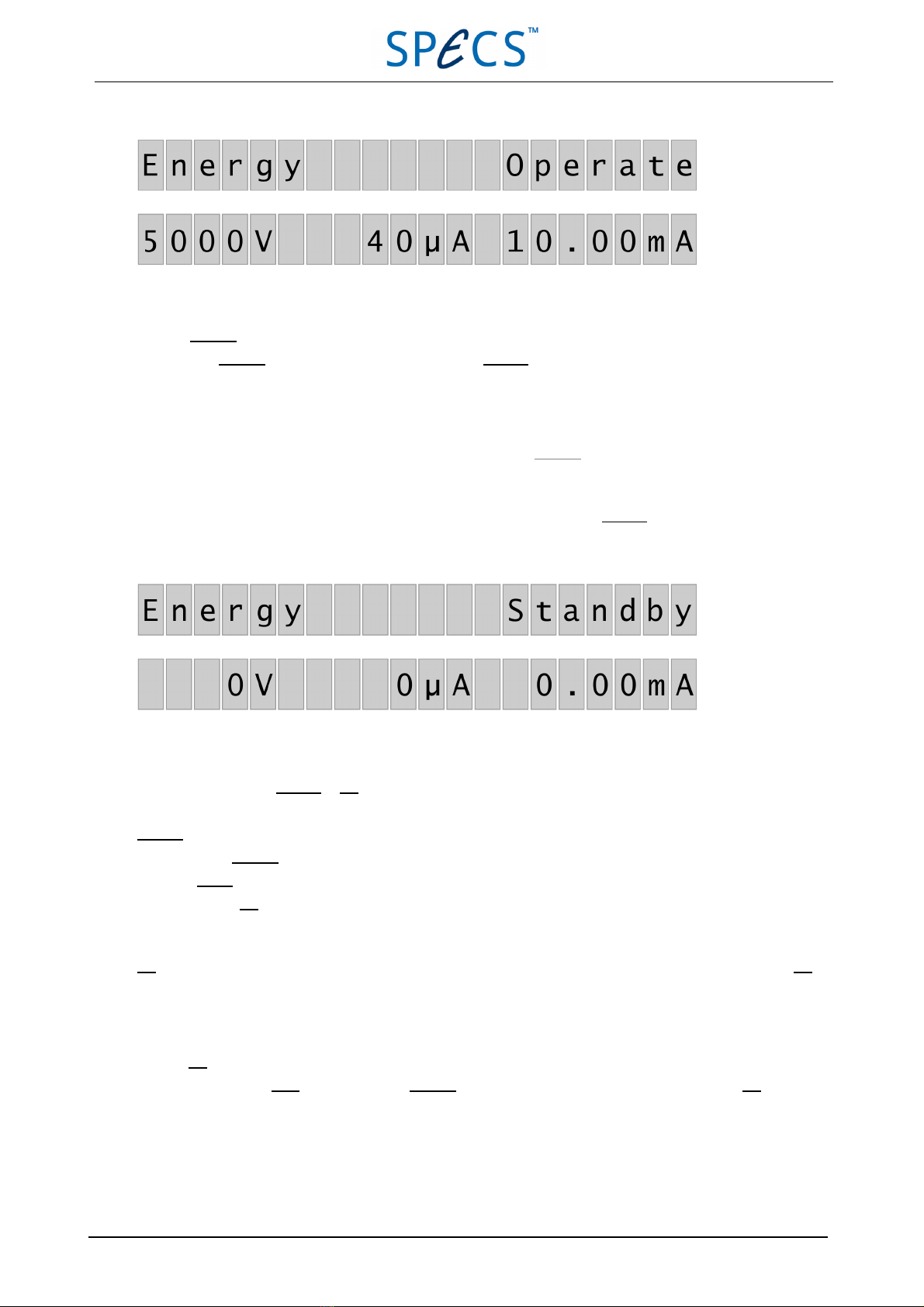
Figure 3: Operate mode
To leave Operate mode:
■Press the Operate button. The PU IQE 12/38 will go into Standby mode.
■You can set the timer to switch the ion source off after a predefined time. Please refer to "Timer" on page 19 for
more details.
Note: The high voltage is automatically switched off when you leave Operate mode.
3.3.2 Standby
When you are not using the ion source to generate ions, you should switch it into Standby mode. This prolongs the fil-
ament lifetime and reduces power consumption. The filament current is limited to 3 A, resulting in no emission current.
Figure 4: Standby mode
If the PU IQE 12/38 is in Standby or Off mode, none of the red lights on the front panel should be active.
Standby mode is activated under the following circumstances:
■By pressing Operate while in Operate mode.
■After Degas mode operation has finished.
■After exiting Off mode.
3.3.3 Off
Off mode means that no high voltage is applied to the ion source and no filament current flows. You should select Off
mode when performing high pressure experiments or gas deposition. In addition, there are a number of configuration
options available in Off mode—see"Setting Up the Power Unit" on page 19.
To enter Off mode:
■Press and hold the Num button, then press Operate. The display will show that the PU IQE 12/38 is in Off mode.
10 April 26, 2013 PU IQE 12/383.0
Chapter 3 Front Panel Control

Chapter 3 Front Panel Control
Figure 5: Off mode
Note: The PU IQE 12/38 is in Off mode when the power is switched on.
To leave Off mode:
■Press Operate. The PU IQE 12/38 switches back into Standby mode.
3.3.4 Degas
Degas mode is used to bake out the electrodes of the ion source in order to clean the ionizer stage. The emission current
rises slowly to avoid fast pressure increases in the vacuum chamber.
The following limitations apply to Degas mode in order to prevent the filament from burning out:
■Final emission current is 15 mA.
■Maximum filament current is 5.5 A, even if the final emission current is not reached.
An error message appears in the display if the final emission current cannot be reached.
During the degas procedure, operation is indicated by the red light above the Degas button and the word "Degas"
appears in the upper right area of the display.
Figure 6: Degas mode
To start Degas mode:
■Press the Degas button. It cannot be activated when the source is in Operate mode. The unit will beep to indicate
that it is in Operate mode.
To stop Degas mode:
■Press the Degas button again. This will stop the mode immediately.
Note: The PU IQE 12/38 automatically leaves Degas mode three minutes after the final emission current is reached.
3.4 Viewing and Modifying Parameters
You can change the contents of the display to show the values of various parameters by pressing the following buttons
on the front panel:
PU IQE 12/383.0 April 26, 2013 11

■Emission
■Energy
■Timer
After displaying a parameter, you can change its value. You can store sets of parameter values and use them later using
the Store and Recall keys.
The following sections describe the parameters and the procedure for storing parameter sets in more detail.
3.4.1 Store and Recall
You can save up to ten sets of parameter values for later use. This allows you to set up the ion source for certain exper-
imental conditions and easily recall the operating parameters later.
There are two kinds of data type:
■User data. These values consist of standard operating parameters used for operating the ion source. You can save
up to nine parameter sets.
■Machine data. These values are general setup parameters for the PU IQE 12/38. You can save one set of machine
parameters.
Table 2 shows a summary of the parameters that make up user and machine data.
User data Machine data
Parameter Factory setting Parameter Factory setting
Energy 5000 V ILimit 5.5
Emission 10 mA IStandby 3.0
Extractor 95.39 % IEEE-488 address 0
Focus 1 77.29 % DS100 mode 0
Focus 1 77.29 % Remote mode HV off
Pos X 0 mm Baud rate 1200
Pos Y 0 mm Scan Mode Intern
Width X 0 mm Time Per Dot 30 μs/dot
Width Y 0 mm Blanking X 1 %
Blanking Y 1%
Phi 0º
Theta 30º or 0º
Blank Level 0
L 31.5 mm
M 11.5 mm
Deflect X 48 V/º
Deflect Y 72 V/º
Table 2User and machine data parameters
Storing and Recalling User Data
To store user data:
1. Set the Energy and Emission parameters to suitable values for your experiment.
2. Press the Store button. The LEDs above the Num and Modify buttons will light.
12 April 26, 2013 PU IQE 12/383.0
Chapter 3 Front Panel Control
Table of contents
Other SPECS Power Supply manuals

Popular Power Supply manuals by other brands


I-Tech
I-Tech IT6302 user manual

Eaton
Eaton Powerware Prestige Series 1500 VA Installation and operator's manual

Danfysik
Danfysik SYSTEM 9100 user manual

Sonnen
Sonnen SonnenProtect 1300-AU-IN-ATS installation instructions

Pulsar
Pulsar PSBEN 3012D/LCD manual

Alpha Technologies
Alpha Technologies APP 9022S Installation and operation manual