Sonnen SonnenProtect 1300-AU-IN-ATS User manual


2
Table of Contents
1 Information about this document.....................................................................................................................................4
1.1 Target group of this document...................................................................................................................................4
1.2 Designations in this document...................................................................................................................................4
1.3 Explanation of symbols................................................................................................................................................4
2 Safety....................................................................................................................................................................................5
2.1 Intended use..................................................................................................................................................................5
2.2 Qualified electricians..................................................................................................................................................5
2.3 Installation requirements of the sonnenProtect....................................................................................................6
2.4 Modifications or changes to the product environment........................................................................................6
2.5 Operational voltage of the sonnenProtect.............................................................................................................6
3 Product description............................................................................................................................................................7
3.1 Technical data................................................................................................................................................................7
3.2 System components....................................................................................................................................................8
3.3 Function ........................................................................................................................................................................8
4 Transport and storage........................................................................................................................................................9
5 Mounting..............................................................................................................................................................................9
5.1 Scope of Delivery.........................................................................................................................................................9
5.2 Selecting the installation location...........................................................................................................................10
5.2.1 Requirements for the installation location of the sub-board..........................................................................10
5.2.2 Observe minimum distances................................................................................................................................10
6 Accessory installation.......................................................................................................................................................11
6.1 Installing the sonnenProtect 1300-AU-IN-ATS accessory................................................................................... 11
6.3 Connecting the cable and strands.......................................................................................................................... 12
6.3.1 Removing the dummy plug.................................................................................................................................... 12
6.3.2 Installing the cable gland....................................................................................................................................... 12
6.3.3 Wiring the output cable......................................................................................................................................... 13
6.3.4 Connecting the cables and strands.....................................................................................................................14
6.4 Completing installation............................................................................................................................................ 15
6.4.1 Connecting to load circuits via backup sub-board............................................................................................ 15
6.5 Monitoring the backup loads................................................................................................................................... 15
7 Commissioning.................................................................................................................................................................. 16
7.1 Commissioning the storage system......................................................................................................................... 16
7.1.1 Switching on the storage system...........................................................................................................................16

3
7.1.2 Switching on the grid voltage................................................................................................................................16
7.2 Testing function ..........................................................................................................................................................17
7 Troubleshooting................................................................................................................................................................18
8 Decommissioning ............................................................................................................................................................. 19
9.1.2 Disposal..................................................................................................................................................................... 19

4
1 Information about this document
This document describes the installation of the sonnenProtect 1300-AU-IN-ATS accessory within the main unit
of the sonnenBatterie eco 9.43 storage system containing a minimum of 7.5kW (x3 modules) of storage
capacity.
►Read this document in its entirety before beginning the installation work.
►Keep this document in the vicinity of the sonnenBatterie.
1.1 Target group of this document
This document is intended for accredited sonnen installers & qualified electricians.
The actions described here must only be carried out by accredited sonnen installers & qualified electricians.
The installation and commissioning of the sonnenBatterie and sonnenProtect 1300-AU-IN-ATS mustbe carried
out by an accredited sonnen installer.
1.2 Designations in this document
The following designations are used in this document:
complete designation designation in this document
sonnenBatterie eco 9.43 storage system
sonnenProtect 1300-AU-IN-ATS sonnenProtect
1.3 Explanation of symbols
Extremelydangeroussituationleadingtocertaindeathor seriousinjury
if the safety information is not observed.
Dangerous situation leading to potential death or serious injury if the
safety information is not observed.
Dangerous situation leadingto potential injury ifthe safety information
is not observed.
Indicates actions that may cause material damage. Important
information not associated with any risks to people or property.
Symbol Meaning
►Work step eps in a defined order
5
2 Safety
2.1 Intended use
The sonnenProtect 1300-AU-IN-ATS is an emergency power unit accessory designed to supplement the
sonnenBatterie eco 9.43. The sonnenProtect provides power to be supplied to a connected sub-board and load
circuits if a grid outage occurs.
Improper use poses a risk of death or injury to the user or third parties as well as damage to the product and
other items of value.
The following points must therefore be observed to comply with the intended use of the product:
Only install the sonnenProtect within the right storage system.
The sonnenProtect must be installed by an accredited sonnen installer & qualified electrician.
The sonnenProtect must only be connected within the storage system as described here. The output of
the sonnenProtect must not be connected to the building mains.
Only connect electrical loads that do not exceed the nominal power (in continuous operation) and
maximum power (when switched on) of the sonnenProtect (1300W).
Failure to comply with the conditions of the warranty and the information specified in this document
invalidates any warranty claims.
2.2 Qualified electricians
Improper installation can result in personal injury and/or damage to components. For this reason, the
sonnenProtect mustonly beinstalled andcommissioned by accreditedsonnen installers &qualifiedelectricians.
Authorised electricians must meet the following criteria:
The electrician must be a person with technical qualification, sufficient experience and current
electrical license to enable him/her to avoid dangers which electricity may create.
The electrician must also be a fully accredited sonnen installer certified by sonnen Australia.
6
2.3 Installation requirements of the sonnenProtect
Incorrect installation can lead to injury to yourself or others and cause damage to property.
The sonnenProtect accessory must only be installed as described in the product documentation.
2.4 Modifications or changes to the product environment
The sonnenProtect must only be installed in its original state without any user modifications and only
when in perfect working order.
Safety devices must never be overridden, blocked or tampered with.
The interfaces of the sonnenProtect and the storage system must be wired in accordancewith the
product documentation / installation manual.
All repairs on the sonnenProtect must be performed by authorised sonnen service technicians only.
2.5 Operational voltage of the sonnenProtect
The sonnenProtect is connected to live electrical parts, which poses a risk of electrical shock. The storage
system inverter also contains capacitors which carry voltage even after the storage system is switched off. As
the sonnenProtect is directly connected to the inverter of the storage system, this means that the voltage
from the inverter also flows into the sonnenProtect. Therefore:
►Disconnect the sonnenProtect from the power (see 8.2).
►Wait five minutes untilthe capacitors have discharged.
7
3 Product description
3.1 Technical data
System data sonnenProtect 1300-AU-ATS
Maximum power 1,300 W
Nominal power 1,300 W
Output voltage (AC) 240 V +/- 10 %
Nominal frequency 50 Hz
Network configuration in emergency operation IT
Operating concept Single-phase RCD protected wired supply
Switchover time approx. 15.0 seconds
Dimensions
Dimensions (H/W/D) in mm 120/50/140
Weight in kg approx. 0.65 kg
Safety
Protection Standard IEC 61009-1; AS/NZ 61009-1
Protective functions Overcurrent & Earth Leakage
Degree of protection IP 30 (as per sonnen eco 9.43 main unit)
Ambient conditions
Ambient temperature range 40 °C
Storage temperature range 50 °C
Transport temperature rang - 50 °C
Maximum relative humidity 90 %, non-condensing
Permissible installation altitude 2,000 m above sea level
Additional ambient conditions As prescribed for the storage system
8
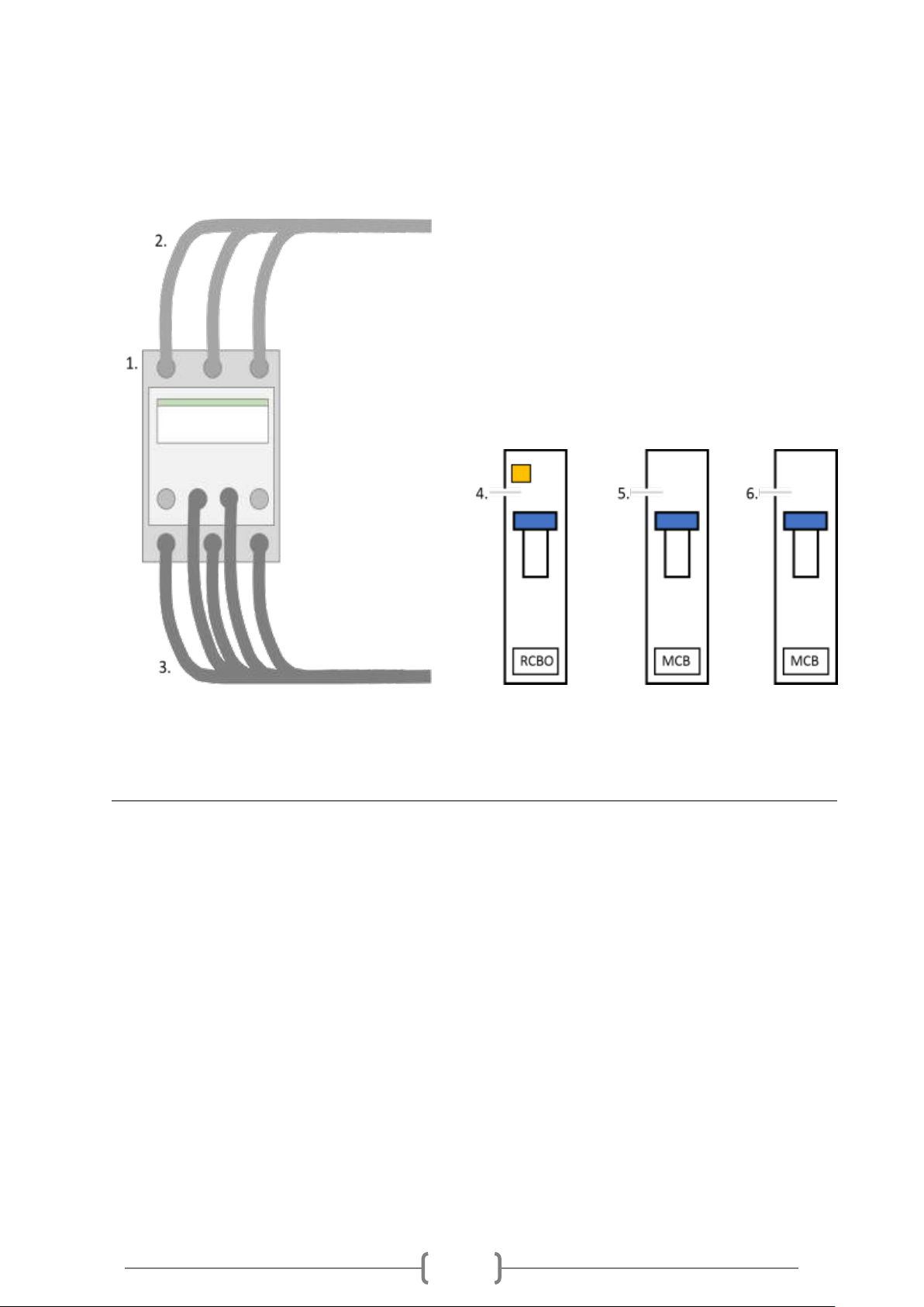
3.2 System components
No. Designation Function
1 sonnenProtect1300-AU-IN-ATS Contactor module
2 Inverter connector cable Grid & Backup supply connection
3 Output cable Connection cable to backup sub-board
4 30mA RCBO 10A RCD for installer to connect to AC output
5 25A MCB Main isolator for sonnenBatterie AC grid supply
6 6A MCB Main isolator for backup circuits after the RCBO
3.3 Function
The outlet cable of the sonnenProtect supplies electrical power both in grid and emergency operation. The
switchover time between grid and emergency operation is stated in the technical data. In the event that the
sonnenBatterieis turnedoff orhas anunexpected issue, thepower supplytothe sonnenProtect backupcircuits
are automatically fed from the normal grid supply.

9
4 Transport and storage
Transport and storage conditions are defined in the product documentation of the storage system.
►Observe the same transport and storage conditions for the sonnenProtect.
5 Mounting
5.1 Scope of Delivery
►Check the following scope of delivery to ensure it is complete.
No. Designation
1 Pre-assembled sonnenProtect 1300-AU-IN-ATS accessory
2 M20 cable gland
3 M20 cable gland nut
4 30mA RCBO 10A RCD for installer to connect to AC output
5 25A MCB Main isolator for sonnenBatterie AC grid supply
6 6A MCB Main isolator for backup circuits after the RCBO

10
5.2 Selecting the installation location
5.2.1 Requirements for the installation location of the sub-board
►Observe the required ambient conditions (see 3.1).
The output cable of the sonnenProtect accessory is approximately 150cm allowing for the following
optimal sub-board location to allow the unit to be easily reached.
5.2.2 Observe minimum distances
►Observethe minimumdistancesspecifiedin Figure6 between
the device and the storage system and neighbouring objects.
►Install the sonnenProtect at the same level as the top edge of
the storage system, if possible.
This keeps the cable lengths as short as possible.
The minimum distances ensure that
The sonnenProtect sub-board can be easily reached and
There is sufficient space for installation and maintenance work.
11
6 Accessory installation
Electrical work on the storage system
Danger to life due to electrocution!
►Switch off the storage system.
►Disconnect therelevant electrical circuits.
►Secure against anyone switching on the device again.
►Wait five minutes so the capacitors can discharge.
►Check that the device is disconnected from the power supply.
►Only authorized electricians & accredited sonnen installers are permitted to carry out electrical work.
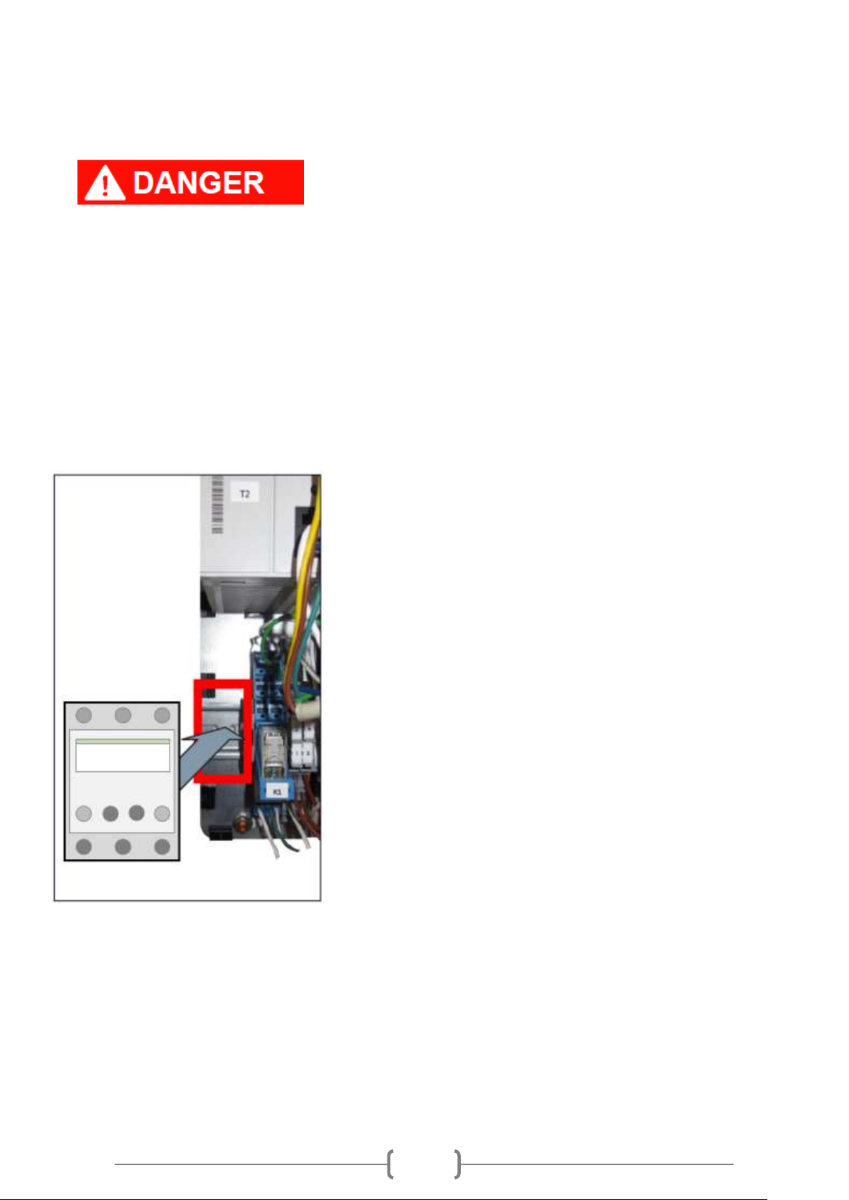
6.1 Installing the sonnenProtect 1300-AU-IN-ATS accessory
►Install the sonnenProtect accessory on the mounting rail. Use
the free space to the left of relay K1.

12
6.3 Connecting the cable and strands
6.3.1 Removing the dummy plug
Tools:
• Screwdriver with a thin blade (0.4 mm)
Remove the dummy plug shown.
A screwdriver with a thin blade can be used for this purpose.
6.3.2 Installing the cable gland
Tools:
• Spanner (25m)
Install the cable gland as shown.

13
6.3.3 Wiring the output cable
►Wire the connection cable of the sonnenProtect through the
cable gland to the inside of the storage system.
►Only pass the output cable through the gland top the
external of the main unit if the backup circuit is to be wired into
a sub-board. If the accessory is not to be immediately
connected, thenleave the output cable & gland within the
internal cavity of the main unit.
►When wiring the output cable into a backup load switch board
it is essential that the 30mA RCBO is used as the main switch
and then in series the supplied 6A MCB is used to protect all sub
load circuits against any excess draw from the backup circuitry.
14
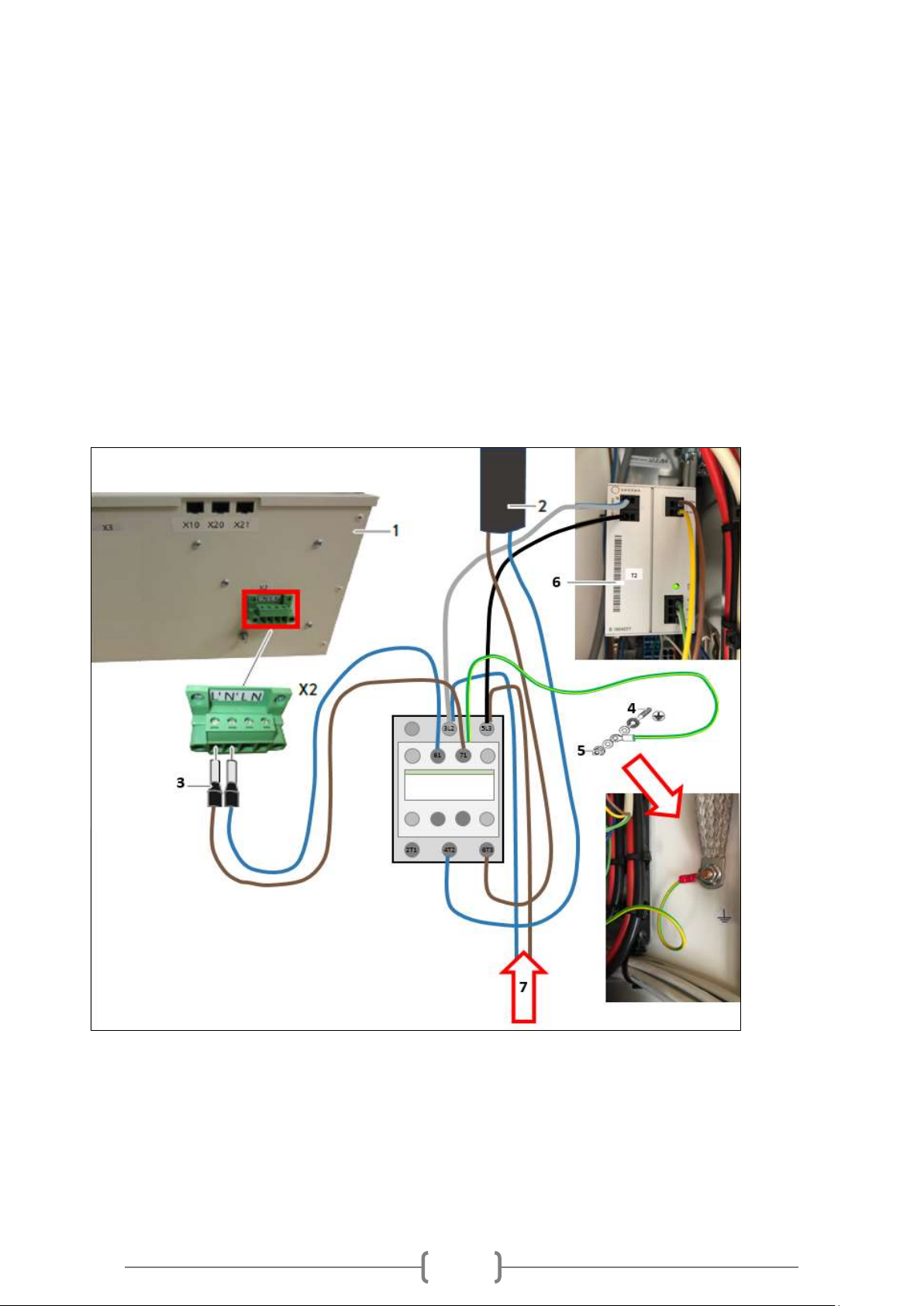
6.3.4 Connecting the cables and strands
►Connect the Active & Neutral cable from the sonnenProtect to the X2 Inverter AC backup power
supply terminal.
►Disconnect both Active & Neutral supply cable from the T2 AC Power Supply by inserting a small flat
screwdriver into the slots adjacent to each terminal input.
►Connect the Active and Neutral AC supply cables taken from the T2 AC Power Supply into the
sonnenProtect contactorarrangement. Insert the Active cable into the 5L3 connection along with the
Black cable. Connect the Neutral cable into the 3L2 connection along with the Grey cable.
►Connect the Black cable into the Lterminal connection of the T2 AC Power Supply and the Grey into
the Neutral terminal connection. To connect both cables insert a small flat screwdriverinto the slots
adjacent to each terminal input.
►Connect the Earth cable to the Earthing connection point by the adjacent door hinge.
1. Inverter
2. sonnenProtect output AC supply cable
3. Inverter Backup supply connection
4. Earthing terminal
5. Locking nut
6. AC Power supply
7. AC grid supply

15
6.4 Completing installation
►Close the storage system.
6.4.1 Connecting to load circuits via backup sub-board
The backup load circuits can be either wired directly from a dedicated backup sub-board supplied via the
sonnenProtect accessory. Alternatively, the circuits can be fed from the existing switch panel which in turn is
fed from the sonnenProtect accessory output cable in addition to the normal grid supply.
The supply to the circuits powered from the sonnenProtect need to be protected by the 30mA RCBO which
has been supplied with the sonnenProtect 1300-AU-IN-ATS kit set.
If the loads are to be fed directly from the existing switch panel, then it is important to clearly label and identify
those circuits being supplied as they will automatically be powered even when the grid has failed (when there is
sufficient battery supply to enable the sonnenProtect).
It is essential that under normal load condition the appliances and/or load circuits being supplied by the
sonnenProtect do not exceed 6A (1300W). All loads after the RCBO will need to be protected by the 6A MCB
supplied with the sonnenProtect accessory set.
In some circumstances the combined power draw of both full charge rate of the sonnenBatterie (3300W) as
well as the full power supply of the sonnenProtect (1300W) need to be considered. To enable this situation,
included within the sonnenProtect 1300-AU-IN-ATS kit set is a 25A main MCB which should be used as the
sonnenBatterie MCB (Main AC isolator). In addition to the higher rating of the protective device the supply
cable itself depending upon route length and location may also need to be replaced with a larger CSA cable.
The sub-board itself and any further protective devices for any sub-circuit after the 6A MCB will need to be
supplied by the installer.
6.5 Monitoring the backup loads
The backup loads to be monitored in normal grid operation must become part of the load measured circuits by
the sonnen system. To enable this the CT position and switchboard configuration must be installed in Setup 4
configuration.

16
7 Commissioning
7.1 Commissioning the storage system
It is essential to follow the instructions in the given order when switching on a storage system with
sonnenProtect otherwise the storage system cannot function properly.
7.1.1 Switching on the storage system
If the storage system cannot be switched on:
►Do not attempt switching on the storage system more than three
times.
►Contact sonnen service!
Further attempts can damage the battery modules.
Fuse switch F1 establishes the connection between the battery and the inverter.
1 Switch on fuse switch F1.
The storagesystem thenstarts upand performs aself-test.Once
theself-testissuccessful,thestoragesystemisreadyto operate.
7.1.2 Switching on the grid voltage
►Switch on the grid voltage using the AC miniature circuit breaker at the switch board.

17
7.2 Testing function
Before the sonnenProtect is operated, a function test must be carried out:
1. Wait until the storage system is completely started up.
2. Check whether the sonnenProtect is behaving as described for grid operation in section 3.3.
3. Switch off the AC miniature circuit breaker at the mains line to the storage system to simulate a grid outage.
4. Check whether the sonnenProtect is behaving as described for emergency operation in section 3.3.
5. Press the test key of the RCBO to simulate an insulation fault of the sub-board.
6. Check whether the sonnenProtect is behaving as described for emergency operation in section 3.3.
7.Ensurethat theilluminatedeclipseofthe sonnenmain unithas turnedgreenwhilstthe unit isin backupmode.
If the sonnenProtect is behaving as described in section 3.3, the function test is successful. The sonnenProtect
can be operated. If the sonnenProtect is not behaving as described in section 3.3, the sonnenProtect must not
be operated.
►In this case, check the wiring (see section 6.3.4).
►Contact sonnen support if the problem cannot be resolved.
18
7 Troubleshooting
Disturbance
Possible reason
Correction
The output of the sonnenProtect
is not supplying any power. The
RCD has switched off.
There is an insulation fault.
►Correct the insulation fault.
The output of the sonnenProtect
is not supplying any power. The
RCD has switched on.
There is a grid outage. The battery
is completely discharged.
►Wait until the public grid begins
supplying power again.
The miniature circuit breaker of
the sub-circuits is switched off.
►Switch on the miniature circuit
breaker.
The storage system is switched
off.
►Switch on the storage system.
The RCD and/or overall power
from the sonnenBatterie is
switching off immediately, or
after the sonnenProtect has been
operating for a longer period.
An electrical consumer with a
power consumption rating that is
too high is connected to the
output of the sonnenProtect.
►Only connect loads with a
power consumption that does not
exceed the nominal power of the
sonnenBatterie.
►Only connect loads with a
power consumption that does not
exceed the maximum power of
the sonnenProtect when switched
on.
available within the
commissioning assistant.
The storage system has a non-
current software version installed.
►Make sure that the storage
system is connected to the
internet.
►Go to the first page of the
commissioning assistant and start
an update by clicking on the
butto

19
8 Decommissioning
Voltage in the event of a grid outage
Danger to life due to electrocution!
The output of the sonnenProtect remains live even in the event of a grid outage or when the main fuses are
switched off.
►The sonnenProtect must be switched off separately.
8.1 Switching off the output
►Switch off the RCD (RCBO).
The power output of the sonnenProtect is switched off.
8.2 Disconnecting the sonnenProtect from the power supply
Before working inside the sonnenProtect, it must be completely disconnected from the power supply:
1. Switch off the RCD (RCBO).
2. Disconnect the storage system from the power supply.
3. Wait at least five minutes until the capacitors inside the storage system inverter have discharged.
4. Check that the voltage is no longer active.
9 Uninstallation and disposal
9.1 Uninstallation
Improper uninstallation of the sonnenProtect
Danger to life due to electrocution!
►The sonnenProtect must only be uninstalled by authorized electricians.
9.1.2 Disposal
The sonnenProtect must not be disposed of as domestic waste!
►Dispose of the sonnenProtect in an environmentally friendly way
through the relevant recycling facility.

Table of contents
Other Sonnen Power Supply manuals


