7
Explanatory Notes – continued –
Function – continued –
If the purging time (5 min.) is exceeded, the logic unit sends the command “Open safety circuit” and
“Evaluate limiter signal of LW level electrode 1 (2)” to the control unit. The command will only be cancelled
when the purging process is successfully finished.
If an external high level alarm is monitored, the signals of the HW level electrode will not be evaluated.
If a purging process is initiated outside the standby time, the interval time will be reset. The factory set
interval time (24h or 72h) is stored on a CF card. This also applies to the standby and the purging time.
These settings are shown at the display of the logic unit.
The corresponding menu of the logic unit enables you to select the control unit with which the logic
unit shall communicate and the level electrode to be monitored. Observe the following specification:
Control unit ID control unit ID level
electrode 1 ID SRL ID level
electrode 2 ID SRL
NRS 1-40
NRS 1-40.1 1 2 4*) 3 5*)
NRS 1-41
NRS 1-40.2 6 7 9*)
*) The software automatically allocates the node ID to the SRL when the control unit (see page 23) is selected.
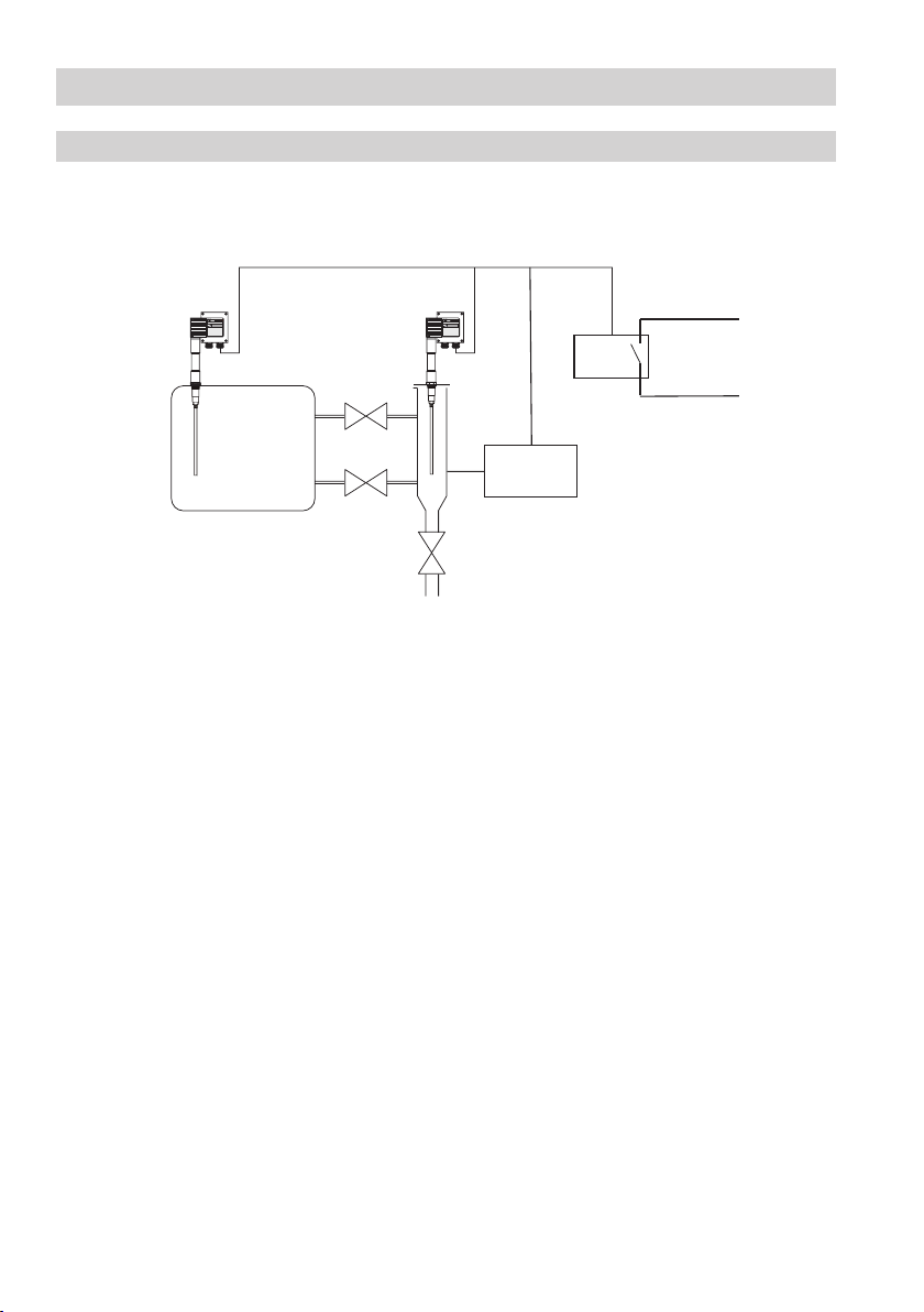
Control units NRS 1-40.1, NRS 1-40.2
In conjunction with the logic unit the control units process the following telegrams:
“Open safety circuit”
“Ignore message from LW level electrode 1 (2)”
For max. 5 minutes the control unit will not evaluate the information coming from the level electrode.
If after 5 minutes the telegram “Evaluate message from LW level electrode 1 (2)” is not received, the
control unit will open the safety circuit. The messages of the other electrode remain valid and will
lead to an interruption of the safety circuit in the event of low water level. If purging takes place at
both electrodes at the same time, the control unit will also interrupt the safety circuit.
“Evaluate message from LW level electrode 1 (2)”
The information from the level electrode will be evaluated as usual. The logic unit sends these tel-
egrams after the purging process is finished.
“Availability message of the SRL 6-40, level electrode 1(2)”
If one or two logic units are used in the system, the control unit expects the availability messages of
the logic units every second. If these messages fail to appear, the safety circuit will be interrupted.
The configuration (NRS 1-40.1, NRS 1-40.2) of the control unit during the commissioning procedure
determines, whether one or two logic units are to work with the control unit.