FIBRO 2486.22 Series Technical specifications

WE LOVE TECHNOLOGY
MEMBER OF THE LAEPPLE GROUP
MAINTENANCE INSTRUCTIONS
GAS SPRING DS
2486.22.
Maintenance instructions Gas spring DS

Document: Maintenance instructions
Document number: 2.7539.00.0915.0100000
Revision: R04-2020
Version: V01
Language:
In the German language, this document is the original version in the EU language of the manufacturer and is labelled
with the German national flag.
In the language of a country of use, this document is a translation of the original version and labelled with the national
flag of the country of use.
This document is referred to as "instructions" in the following text.
Number of pages in this manual including the title page: 30
These instructions are valid for the product
2486.22.
Gas spring DS
This document was created by
FIBRO GMBH
August-Läpple-Weg
DE 74855 Hassmersheim
Phone: +49 (0) 62 66 73 0
Fax: +49 (0) 62 66 73 237
E-mail: [email protected]
Internet: www.fibro.de
© All rights to this document are subject to copyright of the author.
Without the prior written permission of FIBRO GMBH, this document must not be copied or
reproduced, either in full or in part.
The instructions are intended only for the operator of the described only
and must therefore not be made available to uninvolved third parties - in particular to competitors.

Maintenance instructions Gas spring DS 3/30
Contents
1 Safety . . . . . . . . . . . . . . . . . . . . . . . . . . . . . . . . . . . . . . . . . . . . . . . . . . . . . . . . . . . . . . . . . . . . 4
1.1 Safety information . . . . . . . . . . . . . . . . . . . . . . . . . . . . . . . . . . . . . . . . . . . . . . . . . . . . . . 4
1.2 Safety instructions . . . . . . . . . . . . . . . . . . . . . . . . . . . . . . . . . . . . . . . . . . . . . . . . . . . . . . 5
1.3 General instructions . . . . . . . . . . . . . . . . . . . . . . . . . . . . . . . . . . . . . . . . . . . . . . . . . . . . . 5
1.4 Residual risks. . . . . . . . . . . . . . . . . . . . . . . . . . . . . . . . . . . . . . . . . . . . . . . . . . . . . . . . . . 6
2 Maintenance . . . . . . . . . . . . . . . . . . . . . . . . . . . . . . . . . . . . . . . . . . . . . . . . . . . . . . . . . . . . . . . 7
2.1 Components. . . . . . . . . . . . . . . . . . . . . . . . . . . . . . . . . . . . . . . . . . . . . . . . . . . . . . . . . . . 7
2.2 Inspection. . . . . . . . . . . . . . . . . . . . . . . . . . . . . . . . . . . . . . . . . . . . . . . . . . . . . . . . . . . . . 8
2.2.1 Check gas pressure. . . . . . . . . . . . . . . . . . . . . . . . . . . . . . . . . . . . . . . . . . . . . . . 8
2.3 Repairs. . . . . . . . . . . . . . . . . . . . . . . . . . . . . . . . . . . . . . . . . . . . . . . . . . . . . . . . . . . . . . 11
2.3.1 Required spare parts, tools and tool kits . . . . . . . . . . . . . . . . . . . . . . . . . . . . . . 11
2.3.2 Evacuating gas pressure . . . . . . . . . . . . . . . . . . . . . . . . . . . . . . . . . . . . . . . . . . 14
2.3.3 Dismantle gas spring . . . . . . . . . . . . . . . . . . . . . . . . . . . . . . . . . . . . . . . . . . . . . 16
2.3.4 Clean and check components . . . . . . . . . . . . . . . . . . . . . . . . . . . . . . . . . . . . . . 19
2.3.5 Assemble gas spring . . . . . . . . . . . . . . . . . . . . . . . . . . . . . . . . . . . . . . . . . . . . . 20
2.4 Fill with nitrogen . . . . . . . . . . . . . . . . . . . . . . . . . . . . . . . . . . . . . . . . . . . . . . . . . . . . . . . 24
3 Indexes . . . . . . . . . . . . . . . . . . . . . . . . . . . . . . . . . . . . . . . . . . . . . . . . . . . . . . . . . . . . . . . . . . 27
3.1 Third-party products. . . . . . . . . . . . . . . . . . . . . . . . . . . . . . . . . . . . . . . . . . . . . . . . . . . . 27
3.2 Glossary. . . . . . . . . . . . . . . . . . . . . . . . . . . . . . . . . . . . . . . . . . . . . . . . . . . . . . . . . . . . . 27
3.3 Index of figures . . . . . . . . . . . . . . . . . . . . . . . . . . . . . . . . . . . . . . . . . . . . . . . . . . . . . . . 27
3.4 Index . . . . . . . . . . . . . . . . . . . . . . . . . . . . . . . . . . . . . . . . . . . . . . . . . . . . . . . . . . . . . . . 28
4 Appendix. . . . . . . . . . . . . . . . . . . . . . . . . . . . . . . . . . . . . . . . . . . . . . . . . . . . . . . . . . . . . . . . . 29
4.1 Personal notes . . . . . . . . . . . . . . . . . . . . . . . . . . . . . . . . . . . . . . . . . . . . . . . . . . . . . . . . 29

4/30 Maintenance instructions Gas spring DS
Safety
1SAFETY
1.1 Safety information
The statements contained in this document only apply to the maintenance of the stated gas
springs and are only for the use by trained and authorised staff.
Staff has to have the necessary training, experience and product knowledge as well as specialist
tools in order to carry out maintenance work correctly.
Staff has to have fully read and understood this document prior to carrying out any maintenance
work.
Replacement of spare parts without special training or knowledge of the maintenance instruc-
tions and without the specialist tools can be dangerous and may lead to accidents causing se-
vere injuries or even death.
Most accidents during maintenance occur due to disregarding the basic safety regulation.
Noticing a potential danger can prevent accidents from happening. Safety information in this
document warn about potential risks. FIBRO GMBH can not foresee all situations which may
potentially cause risks. The warnings in this document are therefore not all encompassing.
If a work material, an act, a work method or work technique is used which has not been specif-
ically suggested by FIBRO GMBH, then the user has to ensure the safety for himself and other
persons.
The information, descriptions and illustrations in this documents are based on the information
on the basis of information which was available at the point of creation of this document.
Illustrations show examples of a potential gas spring and are not to scale.
Descriptions, tightening torques, operating pressures, measuring methods, illustrations and oth-
er points are subject to change at any time. The changes can have an influence on the compo-
nent's properties. Prior to starting any work, obtain the currently available information.
Maintenance instructions Gas spring DS 5/30
Safety
1.2 Safety instructions
These instructions contain safety notices intended to draw attention to possible dangers that
should be observed to prevent injury.
The pertinent text describes
• the type of danger
• the source of danger
• the options for preventing injuries
• the consequences in case of non-observance of the warning notices
The safety instructions are emphasised by a colour signal bar with warning triangle and signal
word.
The signal bars have the following meaning:
DANGER!
A safety notice on a red signal bar with the signal word DANGER designates a hazard
with a high risk level which, if not avoided, will result in death or severe injury.
WARNING!
A safety notice on an orange signal bar with the signal word WARNING designates a haz-
ard with a medium risk level which, if not avoided, might result in death or severe injury.
CAUTION!
A safety notice on a yellow signal bar with the signal word CAUTION designates a hazard
with a low risk level which, if not avoided, could result in minor or moderate injury.
1.3 General instructions
In addition to the safety notices, these instructions contain information that must be observed to
prevent property damage.
The pertinent text describes
• the possible reason for property damage
• the possibilities for preventing property damage
Notices of possible property damage are emphasised by a blue signal bar and the signal word
ATTENTION.
NOTICE
Notices for the prevention of property damage are not related to possible injuries.
Furthermore, these instructions contain general information on use.
General information on use and tips for certain applications are emphasised with a blue
information symbol.

6/30 Maintenance instructions Gas spring DS
Safety
For safe maintenance further, applicable documents are necessary. The information in these
documents have to be adhered to.
1.4 Residual risks
WARNING!
Filled gas springs are under high internal pressure.
Before repairing, drain the nitrogen completely.
To drain, open the valve carefully and only slightly
Wear safety glasses. Eye injuries due to nitrogen leaks
After removing the locking screw, never bend directly over the valve. Never direct the fill
opening towards persons
Only unscrew the valve when there is no more nitrogen flowing out and the piston rod can
be pushed in by hand. Injuries due to valve flying out.
If assembled incorrectly, parts may be propelled out after filling. Observe the precise instal-
lation position of the spare parts. Never direct the piston rod towards persons. Injuries pos-
sible due to parts flying out.
WARNING!
Use of incorrect spare parts
Installing the incorrect spare parts results in a loss of safety.
After filling with nitrogen, parts may be propelled out due to internal pressure.
Before repair, always ensure that the correct set of spare parts is being used.
Injuries possible due to parts flying parts.
NOTICE
Damages during repair
Always use protective jaws when clamping a gas spring into a vice. Ensure a clean environment.
Grooves, bumps or other damages can cause leakages.
Never exercise undue force to the gas spring during repair. Protect against damages.
Let nitrogen flow in slowly during the filling process. The valve of the gas spring can be dam-
aged.
For the filling process, only use pure nitrogen N2 of Grade 5.0 purity or higher.
Highest permissible filling pressure: 150 bar (2175 psi).
Gas spring operating instructions
Safety data sheet "Exchange of spare parts"
Operating instructions filling and control fitting.
Maintenance instructions Gas spring DS 7/30
Maintenance
2 MAINTENANCE
2.1 Components
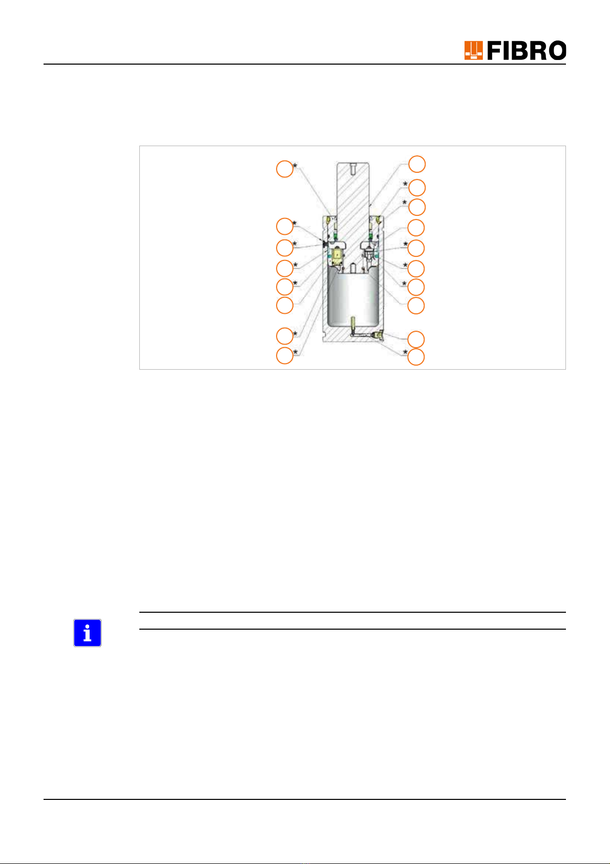
Fig. 2-1 Components of the gas springs
1 Piston rod
2 Guide
3 Dirt ring guard
4 Circlip
5 Warning tape
6 Locking screw on service port
7 Separated piston disc
8 Guide ring
9 Filter screen
10 DS piston seal
11 Flow restrictor
12 DS piston
13 Sealing ring
14 Non-return valve
15 Circlip halves
16 DS piston O-ring
17 G 1/8 Fill opening locking screw
18 Valve
The components marked * are included in the spare parts set.
18
17
15
13
11
9
7
4
3
1
16
14
12
10
8
6
5
2

8/30 Maintenance instructions Gas spring DS
Maintenance
2.2 Inspection
2.2.1 Check gas pressure
NOTICE
Use the tools given below for the test. The tools are available from FIBRO GMBH. Damage to
the gas springs when using other tools.
Pos. Description Article number
[A] Filling and checking equipment 2480.00.32.21
[B] G1/8" filling adapter 2480.00.32.11
[C] Filling hose 2480.00.31.02
Cylinder pressure reducer (optional) 2480.00.32.07
Observe the operating instructions for the filling and checking equipment
2480.00.32.21.
G1/8“
A B C

Maintenance instructions Gas spring DS 9/30
Maintenance
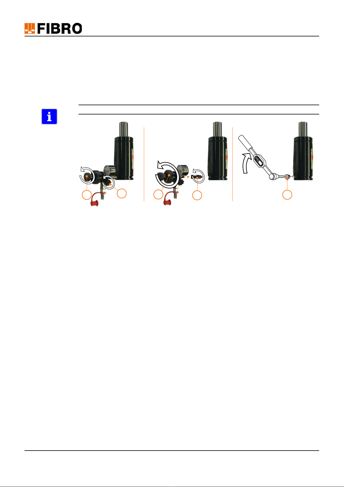
1) Prepare filling and checking equipment.
– Turn the small knob (a) to the left as far as it will go. This will move the release pin (b)
into the retracted position.
– Close the outlet valve (c).
– Screw the filling adapter onto the M6 thread on the fittings. In the process, ensure that
the washer seal is located on the M6 thread.
2) Carefully unfasten the G1/8" locking screw via the fill opening of the gas spring using an
Allen wrench.
3) Unscrew and remove the locking screw.
4) Screw the filling and checking equipment into the fill opening of the gas spring by turning the
large knob.
5) Turn the small knob inwards. The release pin opens the valve. Caution! Do not turn the re-
lease pin inwards too far. Otherwise the valve may be damaged.
6) Read the filling pressure on the manometer display.
The permissible filling pressure is printed on the gas spring. If the filling pressure is too low, the
nitrogen must be topped up (see chapter 2.4 "Fill with nitrogen" on page 24).
a
c
1.
b
2. 5.
6.
4.
3.
10/30 Maintenance instructions Gas spring DS
Maintenance
7) After checking, turn the small knob to the left as far as it will go. The release pin moves into
the retracted position and closes the valve.
8) Slowly open the knob on the outlet valve and bleed the fittings.
9) Unscrew the fittings from the gas spring by turning the large knob.
10) Unscrew the filling adapter.
11) Screw the G1/8" locking screw into the fill opening of the gas spring.
– Tighten using a tightening torque of 15 - 18 Nm (11-13 lb-ft).
The locking screw has a sealing function and must always be fitted.
9. 11.
10.
8.
7.
Maintenance instructions Gas spring DS 11/30
Maintenance
2.3 Repairs
2.3.1 Required spare parts, tools and tool kits
NOTICE
Damage to the gas pressure spring if other spare parts are used
Only use genuine spare parts from FIBRO GMBH.
All spare parts included in the spare parts kit must always be replaced completely.
Spare parts set for gas spring 2486.22.
The spare parts set comprises:
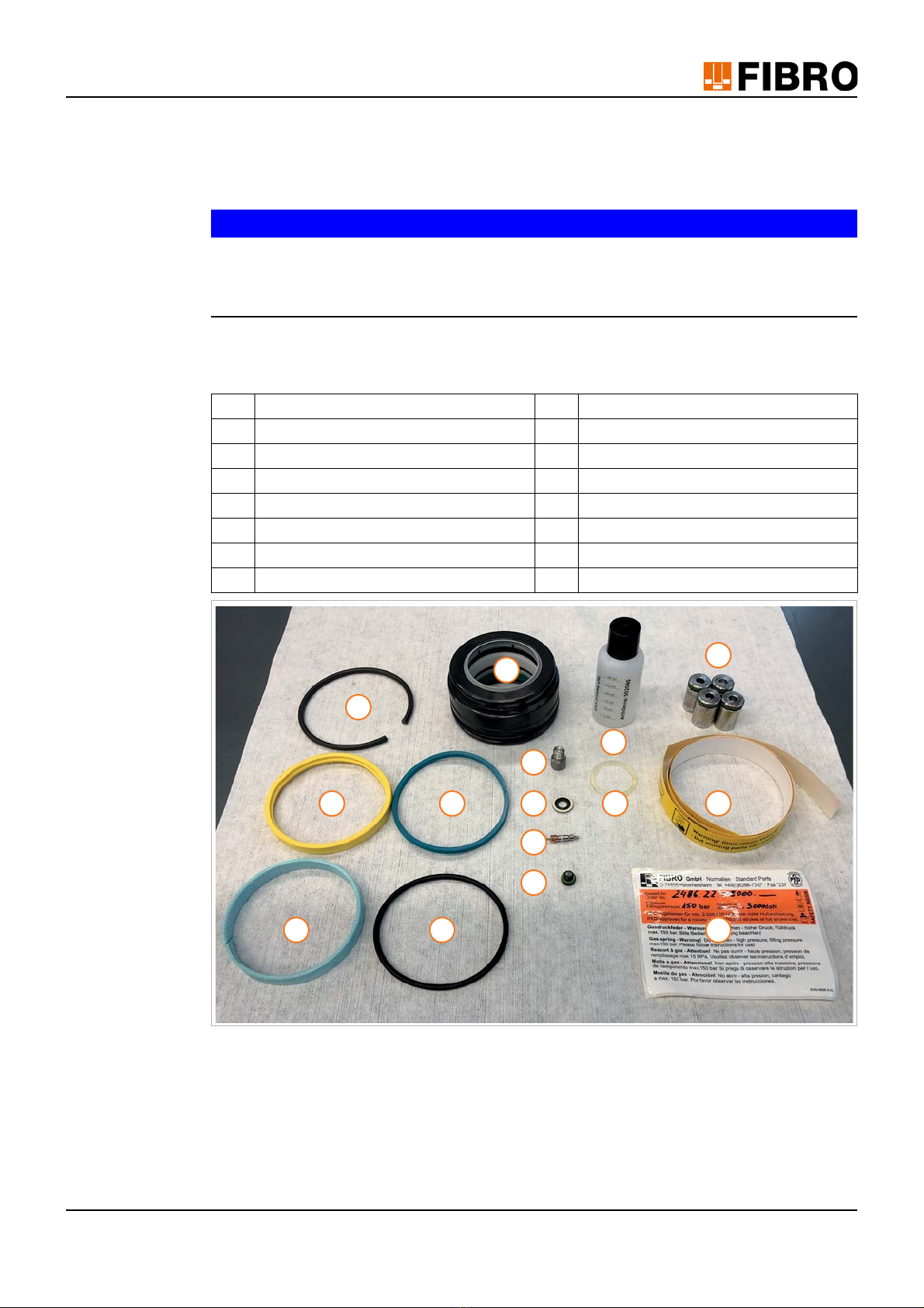
Fig. 2-2 Spare parts set for gas spring 2486.22.
1 Guide 2 Circlip
3 Dirt ring guard 4 Guide ring
5 DS piston seal 6 DS piston O-ring
7 Flow restrictor 8 Filter screen
9 Valve 10 Locking screw on service port
11 Special oil 35 ml ( 248.00.50.) 12 O-ring on piston rod
13 Non-return valves 14 Warning tape
15 Sticker
6
7
8
9
11
5
4
3
1
15
14
10
12
13
2

12/30 Maintenance instructions Gas spring DS
Maintenance
NOTICE
Damage to the gas pressure spring if other resources and tools are used.
Use the resources and special tools listed below for repairs. The resources and tools can be
obtained from FIBRO GMBH.
Equipment and tools
Equipment:
Observe the operating instructions for the filling and checking equipment
2480.00.32.21.
Pos. Description Article number
[A] Filling and checking equipment 2480.00.32.21
[B] G1/8" filling adapter 2480.00.32.11
[C] Filling hose 2480.00.31.02
Cylinder pressure reducer (optional) 2480.00.32.07
G1/8“
A B C
Maintenance instructions Gas spring DS 13/30
Maintenance
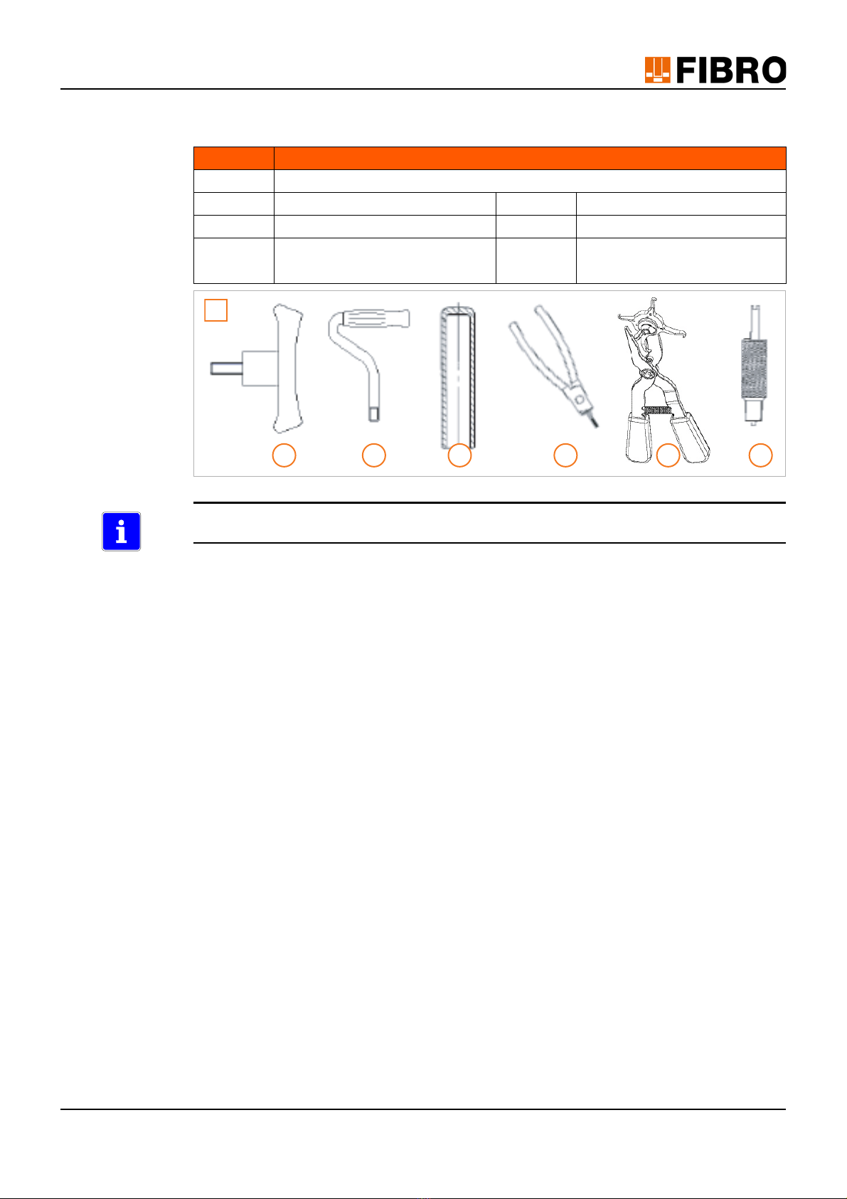
Tools:
Fig. 2-3 Tool set 2480.00.50.11
To open the locking screw, an Allen wrench is required. To tighten the locking screw, a torque
wrench with a hexagon inset socket is required.
• 3 mm wrench size for M6 service port locking screw
• 5 mm wrench size for G1/8" locking screw
Pos. Description
[D] Required parts from tool set (2480.00.50.11)
(1) M8 T-lever (2) M16 T-lever
(3) Mounting sleeve (4) Valve tongs
(5) Circlip tongs (6) G1/8" valve tool
M6 valve tool
D
31 2 4 65
14/30 Maintenance instructions Gas spring DS
Maintenance
2.3.2 Evacuating gas pressure
WARNING!
High pressure
Serious injuries may result if the gas is not fully drained before removing the gas spring.
Only trained personnel with good product knowledge are permitted to carry out the activities
described.
Always wear safety glasses when working on a gas spring.
Never bend directly over a valve. Never direct connections towards yourself or other per-
sons.
Do not allow any extreme forces to be exerted on the gas spring.
When filled, the gas spring is under high internal pressure and must be protected against
damage.
To maintain the maximum service life of the gas spring, always protect it against dirt, caustic
liquids and abrasive dust.
When clamping in a vice, always use protective jaws.
NOTICE
The procedure given below for draining the gas must be followed with care.
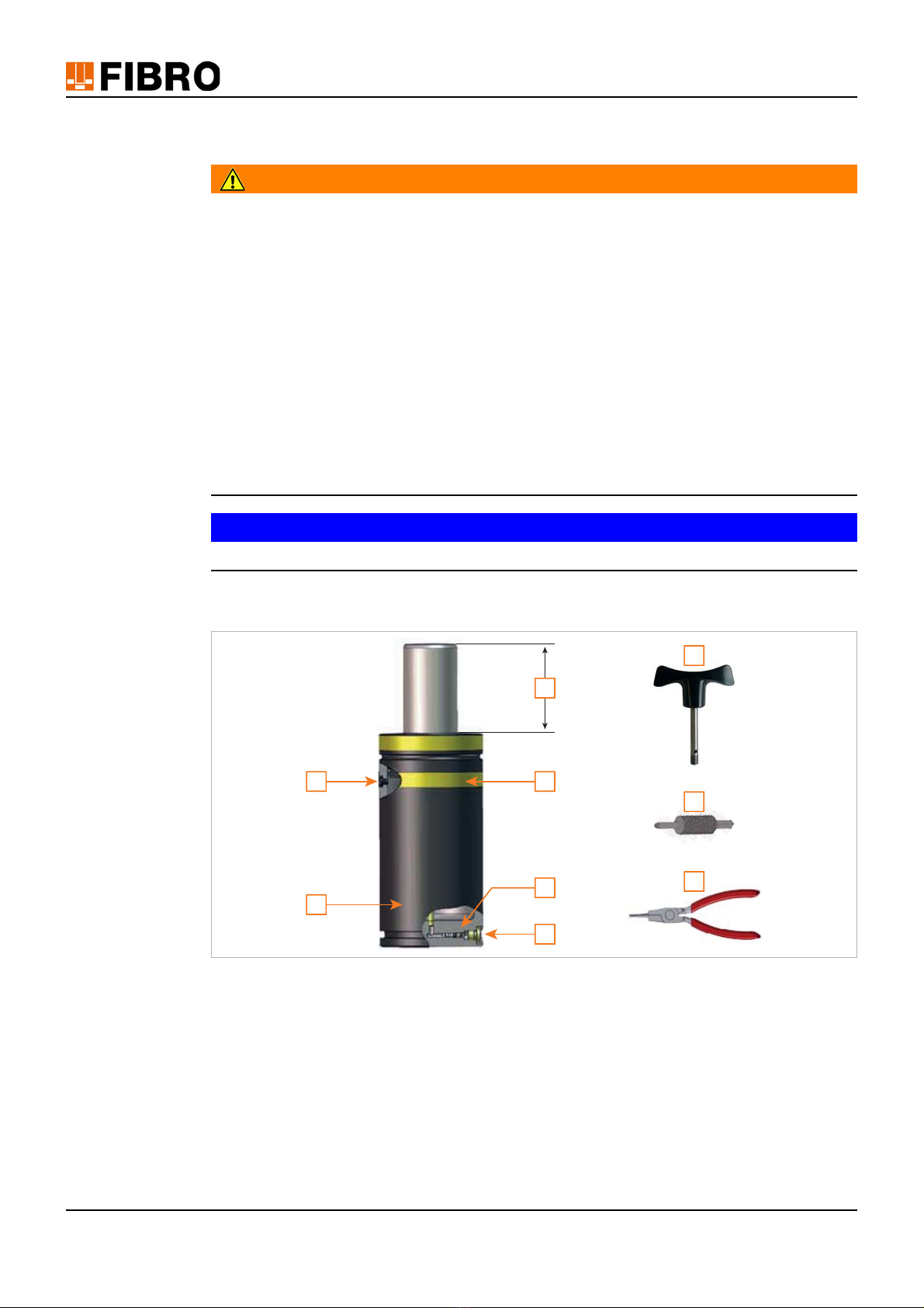
Evacuation instructions for the safe draining of gas
Fig. 2-4 Parts of the DS gas spring / Tools required
1 Locking screw on service port
2 Cylinder pipe
3 Locking screw on fill opening
4Valve
5 Warning tape
6 Maximum stroke
7 M8 T-Lever
8 G1/8“ Valve tool
9 Valve tongs
1
2
3
4
5
6
7
8
9

Maintenance instructions Gas spring DS 15/30
Maintenance
1) Remove warning tape underneath the top C-notch to make the locking screw of the service
port visible.
WARNING!
Escaping gas. High pressure.
The locking screw of the service port is under high internal pressure.
The locking screw is permitted to be opened by a maximum of one full rotation, and must
never be completely removed..
Wear safety glasses.
Leaking gas can cause eye injuries.
2) Use an Allen wrench (3 mm) to turn the locking screw on the service port counter-clockwise
by a maximum of one rotation to slightly open the service port and allow the gas to flow out.
NOTICE
After draining the gas from the service port, the piston rod can be extended.
3) Leave the service port open.
4) Clamp the gas spring in an inclined position (around 30°) in a vice. Piston rod points diago-
nally downwards.
5) Use an Allen key (5 mm) to detach and unscrew the locking screw via the fill opening of the
gas spring..
WARNING!
Escaping gas. High pressure.
Slowly actuate the valve by screwing in the valve tool.
Wear safety glasses.
Leaking gas can cause eye injuries.
6) Screw in the threaded end of the valve tool into the fill opening until the valve opens and the
gas escapes.
7) Allow gas to flow out slowly and completely.
NOTICE
The valve is not permitted to be removed until both pressure chambers of the gas spring are
completely empty.
8) Check the fill level.
– Screw the T-lever into the piston rod thread.
– When the piston rod can be moved up and down by hand, the gas spring can be regard-
ed as drained.
9) After draining with the other end of the G1/8" valve tool, unscrew the valve out of the thread
completely.
10) Remove the valve from the fill opening using the valve tongs and dispose of.
11) Unscrew and remove the locking screw of the service port.
The gas spring is now prepared for performing maintenance work.

16/30 Maintenance instructions Gas spring DS
Maintenance
2.3.3 Dismantle gas spring
Position of the components, see chapter 2.1 "Components" on page 7.
The gas spring must be evacuated completely (see chapter 2.3.2 "Evacuating gas pressure"
on page 14).
Check: Screw the T-lever into the piston rod. When the piston rod can be moved up and
down by hand without resistance, there is no more gas in the gas spring.
The oil must be completely drained.
1. Remove the dirt ring guard.
2. Knock the guide into the pipe using the mounting sleeve and a hammer until the circlip is
exposed.
3. Lever out the circlip using the circlip tool.
CAUTION!
The circlip is tensioned like a spring and may spring out.
Wear safety glasses.
4. Clamp the gas spring in a vice.
5. Screw the T-lever into the piston rod and remove the piston rod including the guide and DS
piston.
2. 3. 5.

Maintenance instructions Gas spring DS 17/30
Maintenance
6. Remove the guide from the piston rod and dispose of.
7. Remove the blue guide ring from the piston rod.
8. Remove both piston disc halves from the piston rod.
9. Rotate the piston rod with DS piston.
10. Press the DS piston downwards to expose the circlip halves.
11. Remove the circlip halves.
12. Remove the DS piston from the piston rod to expose the O-ring on the end of the piston rod.
7. 8. 10.
18/30 Maintenance instructions Gas spring DS
Maintenance
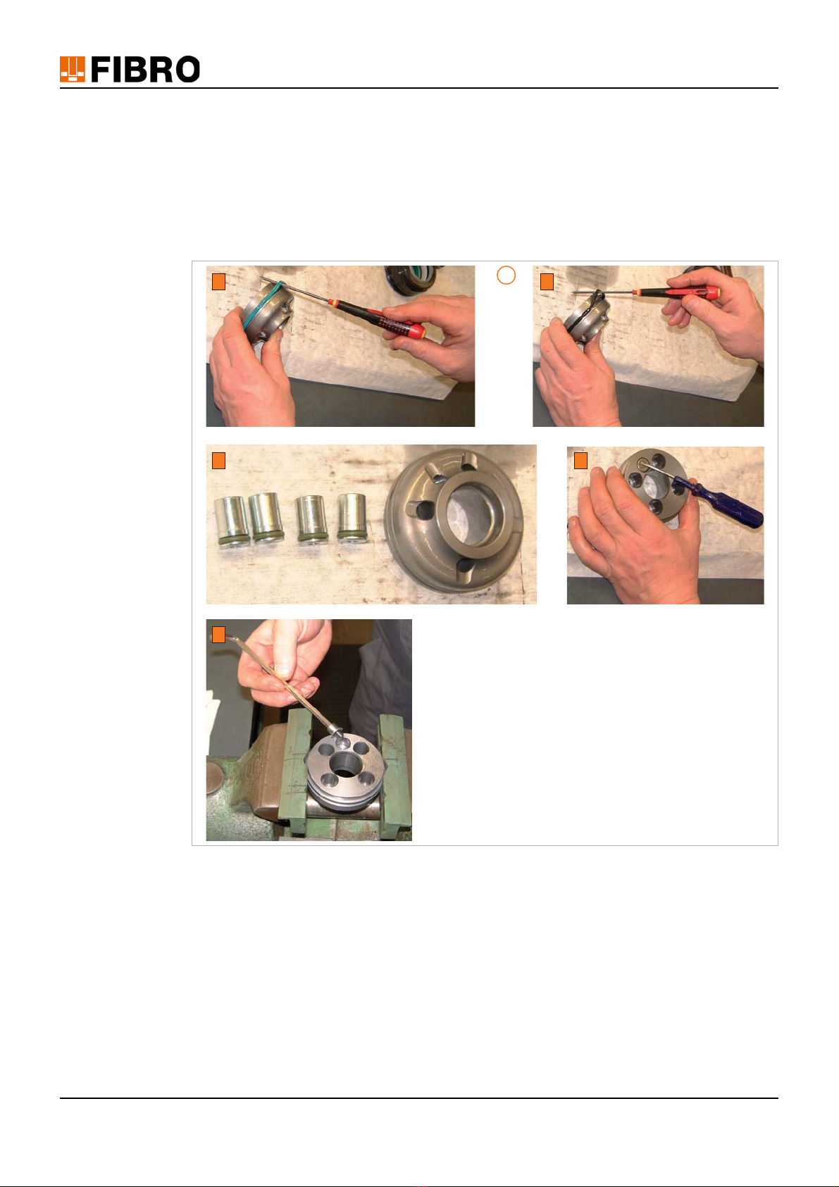
13. Disassembling the DS piston.
a) Remove the piston seal from the DS piston.
b) Remove the O-ring from the DS piston. Ensure that the sealing groove in the DS piston
is not damaged.
c) Push the non-return valves out of the guides of the DS piston.
d) Lever out the filter screen from the flow restrictor.
e) Unscrew the flow restrictor.
13.
a b
c d
e

Maintenance instructions Gas spring DS 19/30
Maintenance
14. Remove the old O-ring from the piston rod.
15. Retain the cylinder pipe, piston rod, DS piston and piston disc halves. Dispose of the remain-
ing components.
2.3.4 Clean and check components
• Clean the cylinder pipe, piston rod, DS piston and piston disc halves.
• Check the interior of the cylinder pipe and piston rod.
– There must not be any scratches or dents on the interior of the cylinder pipe or piston
rod.
– If these parts are in any way scratched or damaged, they must be replaced.
14.

20/30 Maintenance instructions Gas spring DS
Maintenance
2.3.5 Assemble gas spring
NOTICE
Jamming, damage to equipment.
Make sure that the correct piston rod is installed. To check this, place the unmounted piston rod
in the cylinder. The upper end of the piston rod and the cylinder have to be in alignment.
1. Unpack the spare parts set and check for completeness. Spare parts in the spare parts set,
see chapter 2.3.1 "Required spare parts, tools and tool kits" on page 11.
2. Lubricate the piston rod.
3. Insert the O-ring into the second groove of the piston rod.
3.
Table of contents
Other FIBRO Industrial Equipment manuals


Popular Industrial Equipment manuals by other brands

TrueClean
TrueClean ToteTilter Installation, operation and maintenance manual

Nexen
Nexen AIR CHAMP 625 user manual

impro technologies
impro technologies XRH900-1-0-GB Series installation manual

Siemens
Siemens SIRIUS 3RA Equipment manual

Festo
Festo EAMM-U-50-S38-40A Instructions & assembly

Teac
Teac TC-NSRSP-G3 Instructions for use


KSB
KSB 9972073510/200 Operating and maintenance instructions

Elgo
Elgo LIMAX2M Series operating manual

National Instruments
National Instruments NI SMD-7620 Getting started

Dover
Dover OPW 788 Series quick start guide

Siemens
Siemens 3VW9011-0AN73 operating instructions

RaycoWylie
RaycoWylie i4300 installation guide