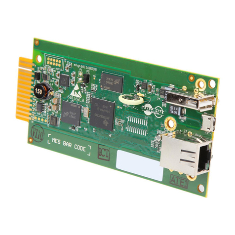
Spectra Engineering RELM BK Radio MX800 T19 User manual

Base Station, Repeater, Receiver and
Transmitter
MX800 -T19 Option
T19 Technical Manual

This page left blank intentionally

Technical Manual
MX800 Transceiver T19 Option
RELM
Wireless
C
o
r
por
a
t
ion
7100 Technology
Drive
West Melbourne, FL
32904
Front Desk: (321)
984-1414
Sales: (800)
821-2900
Service: (800)
422-6281
www.RELM.com
Manual Revision 1.0.3 May 2010
In order to continually improve our products, Spectra Engineering Pty Ltd reserves
the right to alter, without notice and at any time, the equipment and specifications
described in this document.
All performance figures quoted are typical and are subject to normal manufacturing
and service tolerances.
The purchaser is warned that statements made in this document may be inaccurate
due to typographical or other errors or subsequent modifications of the product.
While every care has been taken in the creation of this document, no warranty of
accuracy or reliability is given, in any advice or information contained in this
document. The responsibility for any loss or damage whatsoever arising in any way
or any representation, act or omission whether express or implied (including
responsibility to any person by reason of negligence) is not accepted by Spectra
Engineering Pty Ltd or any director, officer, agent or employee of Spectra
Engineering Pty Ltd.
Copyright © Spectra Engineering Pty Ltd 1997-2010.
This work is copyright. Other than as permitted by Law, no part of it may be
reproduced, stored in a retrieval system or transmitted in any form or by any process
without prior written permission.
Regulatory Information
Federal Communications Commission (FCC) Interference Warning.
Note: The equipment has been tested and found to comply with the limits for a class B digital
device, pursuant to Part 15 of the FCC Rules..
Radio And Telecommunications Terminal Equipment (R&TTE) Directive insures the
protection of health and safety of users, as well as electromagnetic compatibility. Please see
Declarations of Conformity or specification sheet for approved bands and test standards.
These standards & limits are designed to provide reasonable protection against harmful
interference when the equipment is operated in a commercial or residential environment. This
equipment generates, uses and can radiate radio frequency energy. If not installed and used in
accordance with this instruction manual, may cause harmful interference to radio
communication.
1
© SPECTRA ENGINEERING 2010 Revision 1.0.4

MX800 Transceiver
Technical Manual
This page left blank intentionally
2 © SPECTRA ENGINEERING 2010 Revision 1.0.4

Technical Manual
MX800 Transceiver T19 Option
Record Of Changes
Any changes to this manual are recorded on this list. Spectra Engineering
may issue replacement pages to you from time to time. If any updates are
issued, you will also receive a replacement for this page.
Date Version Chapter Changes Pages Changed
30/03/08 1.0.0 Initial Release.
30/03/09 1.0.1 Added Tone Remote Section.
10/06/09 1.0.2 Updated Section 1.8.2 Repeater
Modes Description, Added section
1.11 Line Equalizer.
12/05/10 1.0.3 Added TRC Setup procedure 31,49
14/05/10 1.0.4 Updated TRC Setup Procedure 31,49
3
© SPECTRA ENGINEERING 2010 Revision 1.0.4

MX800 Transceiver
Technical Manual
SAFETY SUMMARY
Although there are no dangerous mains voltages present within the equipment, the
following general safety precautions as would normally apply, should be observed
during all phases of operation, service and repair of this equipment.
AROUND THE EQUIPMENT
To minimise any possible shock hazard from an external power supply or lightning
strike, the chassis or equipment cabinet must be connected to an electrical ground.
To minimise any possible shock hazard from an external power supply or lightning
strike, the chassis & equipment cabinet must be connected to an electrical ground.
A threaded grounding screw terminal is provided on the left-hand side of the radio
chassis for connection to the site ground point (Protective Earth).
Provide adequate ventilation around the rear of the equipment.
DO NOT OPERATE IN AN EXPLOSIVE ATMOSPHERE
Do not operate the equipment in the presence of flammable gases or fumes. Operation
of any electrical equipment in such an environment constitutes a definite safety
hazard.
DO NOT ATTEMPT INTERNAL SERVICE WHILE TRANSMITTING
Thermal or RF burns may result from touching certain components within the power
amplifier module while transmitting or operating the transmitter.
DO NOT SUBSTITUTE PARTS OR MODIFY THE EQUIPMENT
Because of the danger of introducing additional hazards, do not install substitute or
lower voltage parts to the equipment. Return to your authorised distributor.
EXERCISE CAUTION AND CORRECT DISPOSAL OF RF POWER
DEVICES
Most RF power transistors and some RF power hybrids contain Beryllium Oxide.
Although they are normally safe, if physically damaged toxic dust may be released.
Consult your local authority for correct disposal thereof.
WARRANTY CONDITIONS & PRECAUTIONS
The following conditions are not covered by the warranty of the MX800. Please
ensure that the MX800 is not subject to;
1.
Over voltage or Reverse Power Supply Voltage.
2.
Operation in locations subject to abnormal environmental conditions such as
extreme temperatures or ingress of moisture.
3.
Operation of the MX800 Transmitter output into an open or short circuit or an
incorrectly terminated load.
4 © SPECTRA ENGINEERING 2010 Revision 1.0.4

Technical Manual
MX800 Transceiver T19 Option
Table of Contents
1.
T19/26 Line Interface Board.................................................................. 9
1.1.1 Installation.................................................................... 10
1.2
2Wire or 4Wire Selection, Balanced VF ................................... 12
1.3
T19 / T26 Secondary E&M leads .............................................. 12
1.4
Variable & Stepped Tone Encoder............................................ 13
1.4.1
Voting Law.................................................................... 13
1.4.2
Configuration................................................................ 14
1.4.3
Adjustment .................................................................... 14
1.4.4
Calibration.................................................................... 14
1.4.5
Variable & Stepped Tone Encoder Setup Procedure ... 15
1.5
Status Tone Encoding & Decoding (T19 only).......................... 16
1.5.1
Status Tone Encoder & Decoder Setup Procedure....... 16
1.6
Five Tone Encoded / Decoder (SELCALL) .............................. 18
1.6.1
SELCALL Tone Sets...................................................... 18
1.6.2
Selcall Configuration.................................................... 20
1.6.3
Enabling and disabling SELCALL................................ 21
1.6.4
Selecting the tone set..................................................... 22
1.6.5
Configuring the SELCALL commands.......................... 22
1.6.6
Changing the SELCALL transmit preamble ................. 24
1.6.7
Changing the SELCALL acknowledge preamble.......... 24
1.7
Motorola TRICK Emulation...................................................... 25
1.7.1
Repeater States ............................................................. 25
1.7.2
Repeater Modes and Control........................................ 26
1.7.3
Tone Remote Control.................................................... 29
1.7.4
Default Configuration................................................... 30
1.7.5
Tone Remote Control Setup Procedure ........................ 31
1.8
RX Line Output Frequency Compensation................................ 33
1.9
T19/26 Pin outs.......................................................................... 34
1.10
T19/T26 Jumper Settings........................................................... 36
2.
Software Menu System......................................................................... 37
2.1.1 Configuration Menu...................................................... 38
2.1.1
Encoder Configuration Menu ....................................... 38
2.1.2
Hardware Configuration Menu .................................... 39
2.1.1
DTMF Configuration Menu.......................................... 39
2.1.2
Decoder Configuration Menu....................................... 40
2.1.3
Tone Remote Control Configuration Menu .................. 40
2.1.1
Selcall Configuration Menu.......................................... 41
5
© SPECTRA ENGINEERING 2010 Revision 1.0.4

MX800 Transceiver
Technical Manual
2.1.2
Diagnostics Menu......................................................... 41
2.1.3
Calibration Menu.......................................................... 42
3.
Setting up HyperTerminal................................................................... 43
4.
Firmware Upgrade ............................................................................... 49
4.1 Upgrade Procedure .................................................................... 49
4.1.1 Upgrade Steps............................................................... 49
5.
PCB Overlay.......................................................................................... 51
6 © SPECTRA ENGINEERING 2010 Revision 1.0.4

Technical Manual
MX800 Transceiver T19 Option
List of Tables
Table 1-1 T19/T26 Font Panel Leds.......................................................................... 12
Table 1-2 Signal decision levels/points and coresponding tones.............................. 13
Table 1-3 Nominal SELCALL Durations .................................................................. 18
Table 1-4 Standard SELCALL Frequencies.............................................................. 19
Table 1-5 Repeater Functionality.............................................................................. 26
Table 1-6 Line Equalizer Settings ............................................................................ 33
Table 1-7 CN3 Connections..................................................................................... 34
Table 1-8 CN9 Connections..................................................................................... 35
Table 1-9 T19/26 Factory Default Jumper Setting.................................................... 36
List of Figures
Figure 1-1 MX800 T19/T26Option Board .................................................................. 9
Figure 1-2 SELCALL menu....................................................................................... 20
Figure 1-3 Menu with SELCALL disabled................................................................ 21
Figure 1-4 SELCALL tone options............................................................................ 22
Figure 1-5 SELCALL commands menu..................................................................... 23
Figure 1-6 MXTOOLS channel information ............................................................. 27
Figure 1-7 MXTOOLS channel RF mode.................................................................. 27
Figure 1-8 Line Equalizer Response Graph.............................................................. 33
Figure 1-9 CN3 Pin-out Detail (View from Rear of MX800).................................... 34
Figure 1-10 CN9 RJ45 Pin-out Detail (View from Rear of MX800)........................ 35
Figure 2-1 T19/T26 Main Software menu................................................................ 37
Figure 2-2 T19/T26 configuration menu................................................................... 38
Figure 2-3 T19/T26 Encoder configuration menu .................................................... 38
Figure 2-4 T19/T26 Hardware configuration menu.................................................. 39
Figure 2-5 T19/T26 DTMF configuration menu....................................................... 39
Figure 2-6 T19/T26 Decoder configuration menu.................................................... 40
Figure 2-7 T19/T26 Tone Remote Control configuration menu................................ 40
Figure 2-8 T19/T26 Selcall configuration menu....................................................... 41
Figure 2-9 T19/T26 diagnostics menu ...................................................................... 41
Figure 2-10 Calibration Menu.................................................................................. 42
Figure 3-1 HyperTerminal connection description................................................... 43
Figure 3-2 HyperTerminal COM port selection........................................................ 44
Figure 3-3 HyperTerminal communication parameters............................................ 45
Figure 3-4 HyperTerminal disconnect...................................................................... 46
Figure 3-5 HyperTerminal connection properties .................................................... 46
Figure 3-6 HyperTerminal terminal settings............................................................. 47
Figure 3-7 HyperTerminal ASCII setup.................................................................... 48
Figure 4-1 T19/T26 Bootloader prompt.................................................................... 50
7
© SPECTRA ENGINEERING 2010 Revision 1.0.4

Technical Manual
MX800 Transceiver T19 Option
1. T19/26 Line Interface Board.
The MX800 T19 / T26 option board provides the radio base station with utmost flexibility in
system design and capabilities, with an extensive range of new features.
Please consult Spectra, for the availability of these features or software upgrades. Not all features
are currently available.
◆
2Wire (VF Hybrid) or 4Wire Selection, Balanced Audio, Dual E+M,
◆
Base Station Variable Tone Voting
◆
Base Station Stepped Tone Voting
◆
Status Tone Encoding And Decoding (T19 only)
◆
Five Tone Encoded / Decoder (T19 only)
◆
Remote Control Capabilities
◆
VF Line compensation for SINAD Voters
◆
Real-time Clock
Figure 1-1 MX800 T19/T26Option Board
Due to ongoing development please refer to www.spectraeng.com.au for the latest information regarding this option.
Note These are software selectable provided the correct option board is selected/used, and not
all option can be used in conjunction with each other. Some parts many not be populated.
Jumpers referred below are those on this option PCB.
9
© SPECTRA ENGINEERING 2010 Revision 1.0.4

MX800 Transceiver
Technical Manual
1.1.1 Installation
CAUTION: COMPONENTS USED ARE STATIC DAMAGE SENSITIVE! (ESD)
ComponentsRequired:
1.
T26/19 Option PCB & RJ45 Daughter PCB. Qty-1
2.
M3X 25mm Standoff posts. Qty-4
3.
M3X 3mm screws Qty-3
4.
Front panel. Qty 1 (Front Panel upgrade required
to support switch and Led mounting,)
5.
CABLE IDC SKT - IDC SKT 16W 125mm cable Assy. Qty-1
6.
CABLE IDC SKT-IDC SKT 10WAY 150mm cable Assy. Qty-1
7.
CABLE IDC SKT-IDC SKT 16WAY 170mm cable Assy. Qty-1
8.
CABLE IDC SKT-IDC SKT 10W 330mm cable Assy. Qty-1
9.
CABLE IDC DB9M-IDC SKT 10W 195mm cable Assy. Qty-1
10.
CABLE IDC DB15F-IDC SKT 16W 210mm cable Assy. Qty-1
11.
CABLE IDC SKT-IDC SKT 16WAY 210mm cable Assy. Qty1
Test Equipment Required:
1.
Communications Test Set
2.
MX800 Radio Interface Box
Note
When installing cables insure that they are fitted with the correct orientation.
Method:
1.
Remove the cover to the MX800 radio.
2.
Remove mother board from chassis of radio. Note cable connection and orientation.
3.
Install the CABLE IDC SKT-IDC SKT 10W 330mm cable Assy between connector SKI on
the Motherboard (going under nether mother board) and SKU/B on the Option board, taking
note that the cable is correctly orientated. This cable lays under the mother board. Issue cable
is not crushed when refitting mother board.
10 © SPECTRA ENGINEERING 2010 Revision 1.0.4

Technical Manual
MX800 Transceiver T19 Option
4. Refit mother board to chassis. Don’t refit the four screws indicated below on the motherboard
and fit Qty 4 3x20mm standoff posts in the positions where the screws where removed.
Motherboard
3x5mmmachine
screws to be removed
5.
Punch out the RJ45 square on the rear of radio.
6.
Install RJ45 daughter board in the rear of chassis, locate the RJ45 socket into punch hole.
Locate mount holes over chassis stand off. Secure with 3x 3mm screws.
7.
Remove the Link jumpers off Mother Board connector SKK.
8.
Install the CABLE IDC SKT - IDC SKT 16W 125mm cable Assy between connector SKK
on the Motherboard and SKK on the Option board.
9.
Install the CABLE IDC SKT-IDC SKT 16WAY 210mm cable Assy. between connector
AUX3 (SKX) on the Motherboard and SKX on the Option board. This cable will be under
option PCB when mounted.
10. Install the Option Printed Circuit Board onto the 4 standoffs with the 16way connector closest
to DIP2 on the Motherboard. Secure with the qty4 3x5mm machine screws previously
removed.
11.
Install the CABLE IDC SKT-IDC SKT 16WAY 170mm cable Assy. between connector
SKH on the Motherboard and SKH on the Option board.
12.
Install the CABLE IDC SKT-IDC SKT 10WAY 150mm cable Assy. between connector
SKV on the Motherboard and SKV on the Option board.
13.
Remove and replace CN1 with CABLE IDC DB9M-IDC SKT 10W 195mm cable Assy.
Connect to SKU on the Option board.
14.
Remove and replace CN4 with CABLE IDC DB15F-IDC SKT 16W 210mm cable Assy.
Connect to SKH/B on the Option board.
15.
Check that the option board jumpers are in the correct positions for application.
16.
See the appropriate application section for Setup procedure.
11
© SPECTRA ENGINEERING 2010 Revision 1.0.4

MX800 Transceiver
Technical Manual
1.2 2Wire or 4Wire Selection, Balanced VF
Description
Option T19 and T26 both provide the user to be able to select between 2 wire or 4 wire systems,
they also both have balanced and isolated VF I/O as well as isolated E (PTT) and M (Mute) leads.
The T19 has dual E&M leads, this provide a Qualified and Non-qualified M leads as well as E
leads with subtones and with out subtones. The second E&M connection points are found on CN3
DB25 connector.
The E lead is opto isolated and may be asserted by applying a DC voltage between 5V and 48V
with any polarity between CN9 Pins 7&8 (JMP4 & JMP5 removed).
Provision is also made to internally source or Earth (JMP4 and JMP5) so that the activation can
be done Via CN9 Pin8 (+12V DC) or (GND), in which case the E lead is asserted by grounding
or pulled up to 5V (depend on JMP4 & JMP5 settings) on CN9 Pin8
The M lead is relay isolated and the common and normally open contacts are brought out via
CN9 Pins 5&6. The relay contacts are rated at 500mA.
Note
In REV C PCB for 2 wire mode, to have the correct matching for 600R please fit a 560R resistor is in parallel to R77(above IC4) and
across R130 & R129 (Right hand side of PCB above RV4)
1.3 T19 / T26 Secondary E&M leads
The MX800 T19 option board has a secondary E & M lead designated E2 and M2 respectively.
Unlike the primary E & M leads that appear on both the RJ45 and DB25 connector, the E2 and
M2 leads are only present on the DB25. The assertion of the E2-lead will cause the transmitter to
transmit without a subtone, even if one has been programmed for the channel.
The M2-lead is used to indicate the state of the RF (unqualified) mute. The M2-lead can be
programmed to close the relay contacts when the mute opens or operate in reverse. The secondary
E & M leads are enabled in the hardware configuration menu (Configuration Menu -> Hardware
Configuration).
The E2 and M2 Leds on front panel show the activity on these lines only if the “Glide Tone” or
“Stepped Glide Tone” modes are not selected.
Front Panel
LedPosition
Led
Colour
StandardFunction
Glide tone Led Function.
(RF Signal Decision Points)
1
Amber
E1 Lead, indicates status of E1 input.
Level 0 signal (> 0uV)
2
Green
E2 Lead, indicates status of E2 input.
Level 1 signal (> 0.6uV).
3
Green
N/A
Level 2 signal (> 1.0uV)
4
Green
N/A
Level 3 signal (> 2.0uV)
5
Green
M1 Lead, indicates status of M1 input.
Level 4 signal (> 5.0uV)
6
Red
M2 Lead, indicates status of M2 input.
Level 5 signal. User defined
Table 1-1 T19/T26 Font Panel Leds
12 © SPECTRA ENGINEERING 2010 Revision 1.0.4

Technical Manual
MX800 Transceiver T19 Option
1.4 Variable & Stepped Tone Encoder
Variable tone voting is a method of conveying the received signal strength information to a
central arbiter so that an informed decision can be made as to which base station will use its
received audio.
There are two methods of this type of encoder, Variable tone that works by superimposing a
sliding scale audio tone on the received audio at each site, and stepped tone that works by
superimposing a fixed audio tones per decision block. This tone frequency being related to the
received signal strength (RSSI). The tone is removed at the central site and the best audio is
turned around for retransmission. This requires a VF connection between each base station and
the central arbiter.
Prior to a tone being superimposed the receiver VF is notch filtered at the tone frequency.
A Second PTT function designed for mobile voting systems transmits carrier with no modulation
(including no CTCSS) to allow mobiles to vote without lifting the mute in the mobile.
1.4.1
Voting Law
The table below shows the default voting decisions points programmed into the MX800 T19 /
T26 option board. These are the corresponding signal points where by under control of the
microprocessor to generates the appropriate audio tone.
Level 0 refers to the signal level when the mute opens and is less than Level 1. The option board
incorporates a signal noise measurement circuit that needs to be calibrated for the board to
performoptimally.
RF Signal
DecisionPoints
Level
(uV)
Frequenc
y
(Hz)
Squelch closed
N / A
2710
Level 0 signal
> 0
2732
Level 1 signal
> 0.6
2792
Level 2 signal
> 1.0
2856
Level 3 signal
> 2.0
2913
Level 4 signal
> 5.0
2973
Table 1-2 Signal decision levels/points and coresponding tones.
13
© SPECTRA ENGINEERING 2010 Revision 1.0.4

MX800 Transceiver
Technical Manual
1.4.2
Configuration
The configuration procedure for the Variable tone encoder consists of setting up the software and
adjusting the noise circuit for maximum range. The configuration screen is entered via the menu
system using options ‘C’ for configuration, then ‘E’ for encoder and then ‘1’ for Variable tone
encoder.
When the Variable tone encoder is initially enabled it is configured with the system defaults as
shown above, or a previously configured Variable tone voting law. The user can change the
number of Variable tone levels, the Variable tone decision points and tone frequencies. If the user
decides to change any setting all the Variable tone settings will need to be entered.
The number of levels refers to the number of decision points once the mute is opened. Level 0 is
the receiver signal level when the mute just opens; use the appropriate units for the decision
point. The units for the Variable tone decision points can either be in microvolt’s (uV) or decibels
(dBm).
1.4.3
Adjustment
The process for adjusting the noise measurement circuit for range is to inject a signal of about
0.6uV (or approximately -111.4 dBm) into the receiver and measure the filtered noise signal on
the pad between R131 and C67. The voltage should be around 0.7V, use variable resistor RV6 to
adjust the gain.
The Variable tone encoder tone level can be adjusted using variable resistor RV1. This is
typically –20dBm tone level.
The line output level is adjusted using variable resistor RV4, for the desired level. This is
typically –10dBm audio level.
1.4.4
Calibration
Once the board has been configured for Variable tone voting, calibration is performed using
screen prompts in the calibration menu. Enter using the menu system option ‘R’ for calibration
then ‘N’ for noise-floor measurements. The user will then be prompted to adjust the receiver
signal to match the calibration points.
After calibrating the noise floor decision points, the frequency compensation adjustments will
need to be performed. This is done through the menu system using options ‘R’ then ‘C’. The user
will then be prompted to turn off the receiver signal source to initiate the calculations.
14 © SPECTRA ENGINEERING 2010 Revision 1.0.4

Technical Manual
MX800 Transceiver T19 Option
1.4.5
Variable & Stepped Tone Encoder Setup Procedure
This section provides a set by step approach to enable the option board for uses as a Variable
Tone encoder T26
1.4.5.1 Variable & Stepped Tone Encoder- Programming
1.
Connected option Board via the Rs232 port, run terminal software.
2.
Type "RMENU↵" to access inbuilt software menu.
3.
Select Configuration Menu (C)
4.
Select encoder Menu (E)
5.
Select the type of encoder required.
6.
Press the Escape Key.
1.4.5.2 Variable & Stepped Tone Encoder- RX Alignments
1.
Using a 600ohm termination monitor RX line output level. This output is located on the rear
of the MX800, RJ45 Line I/O connector pin 1 & 2 (balanced audio)
2.
Remove JMP20
3.
Set the receiver modulation frequency to 1 kHz and the FM deviation to nominal for the
particular RF receiver frequency of the test channel. At a RF level of –60 dBm.
4.
Adjust Line Output level RV4 to obtain nominal line output level (-10dBm is the default
level).
5.
Set the RF level to 0.6uV (-111.4dBm) on the comm.’s test set.
6.
Using a DVM, monitor the DC volt level at junction of R131 and C67, Adjust RV6 so that
DVM reads 0.7VDC.
7.
Remove RF signal from receiver.
8.
Insert JMP20 in positions 1-2.
9.
Toggle RF signal ‘on’ and ‘off’ to ensure key tone represent mute status.
10.
With the key tone present, adjust RV1 to obtain the required Variable Tone level (-20dBm is
the default level).
11.
Type "RMENU↵" to access inbuilt software menu.
12.
Select Calibration Menu. (R)
13.
Select Variable Tone Calibration points (N)
14.
Follow on screen instructions.
15.
Exit menu system and cycle power to radio.
16.
Insure front panel signal Leds (RSSI Leds) and Key tone changes at the correct RF level
points, see table above.
Note
(Note# Sixth led will not light due to only 5 RF level points are used in this setup)
15
© SPECTRA ENGINEERING 2010 Revision 1.0.4

MX800 Transceiver
Technical Manual
1.4.5.3 Variable & Stepped Tone Encoder -TX Alignments
1.
PTT the transmitter.
2.
Set the transmitter modulation frequency to 1 kHz, -10dBm level injected in through
the rear RJ45 connector, pin3 & 4. (Balanced audio)
3.
Disable Notch Filter JMP9 (Position 1-2)
4.
Disable AGC on Option Board JMP13 (Position 2-3)
5.
Adjust TX input line gain RV5 to obtain 1 Vp-p at IC13 pin 1.
6.
Monitor TX modulation depth and insure it is equal to the nominal deviation level. If
not adjust RV4 on the motherboard to obtain correct level.
1.5 Status Tone Encoding & Decoding (T19 only)
This powerful option board allow the user to be able to monitor the status of the MX800. The
option works by superimposing fixed audio tones per status to line. This provides the current
status on mute open or closed. This signalling is then sent down a 2 or 4 wire line system. The
decoder then processes the status tones and applies the various functions as need. I.e.
Programmable PTT tones, PTT ON & PTT OFF.
RX mute status tone encoder provides a signalling tone either when mute is open or when mute is
closed depending upon system requirement. The signalling tone is notched out from the speech
or noise components on the receiver frequency, to prevent false system decodes.
1.5.1
Status Tone Encoder & Decoder Setup Procedure
This section provides a step by step approach to enable the option board for uses as a Status Tone
Encoder and Decoder.
1.5.1.1 Status Tone Encoder & Decoder- Programming
1. Connected option Board via the RS232 port, run terminal software.
2.
Type "RMENU↵" to access inbuilt software menu.
3.
Select Configuration Menu (C)
4.
Select encoder Menu (E)
5.
Select the type of encoder required.
6.
Press the Escape Key.
7.
Repeat steps 2 & 3
8.
Select Decoder Menu (D)
9.
Select (1) and enter the PTT decode tone.
10.
Also enable AGC (2) And Bandpass filter (3)
11.
Programming is complete.
16 © SPECTRA ENGINEERING 2010 Revision 1.0.4

Technical Manual
MX800 Transceiver T19 Option
1.5.1.2 Status Tone Encoder & Decoder -TX Alignments
1.
PTT the transmitter.
2.
Using a signal generator, apply a 1 kHz Tone with the line up level as required
(default -10dBm), injected into the rear RJ45 connector, pin3 & 4. (Balanced audio)
3.
Disable AGC on Option Board JMP13 (Position 2-3)
4.
Adjust TX input line gain RV5 to obtain 1 Vp-p at IC13 pin 1.
5.
Monitor TX modulation depth and insure it is equal to the nominal deviation level. If
not adjust RV4 on the motherboard to obtain correct level.
6.
Enable AGC by linking in Jmp13 in position [1-2]
7.
Using a signal generator, apply a Key tone to Audio level @-10dB.
[–10dBm0](Default –20dBM)
8.
Adjust RV7 so that the combined audio and key tone signal are set to the required
onset compression level.
1Vp-p at IC13 pin 1. (JMP9 2-3)
(Default compression level are, audio -20dBm and key tone signal is set to -30dBm)
9.
Monitor TX modulation depth and insure it is equal to the nominal deviation level. If
not adjust RV4 on the motherboard to obtain correct level.
1.5.1.3 Status Tone Encoder & Decoder- RX Alignments
1.
Using a 600ohm termination monitor RX line output level. This output is located on
the rear of the MX800, RJ45 Line I/O connector pin 1 & 2 (balanced audio)
2.
Set the receiver modulation frequency to 1 kHz and the FM deviation to nominal for
the particular RF receive frequency of the test channel. At a RF level of –60 dBm.
3.
Remove JMP20 and adjust Line Output level RV4 to obtain nominal line output
level (-10dBm is the default level).
4.
Fit JMP20 in positions [1-2] and remove JMP7.
5.
Toggle RF signal ‘on’ and ‘off’ to ensure key tone represent mute status.
6.
With the key tone present, adjust RV1 so that the ratio of Key tone to Audio level is
@-10dB.(–10dBm0)
7.
Fit JMP7 in positions [2-3]
Two wire Mode only
8.
Using an oscilloscope, monitor the audio on IC4 pin1 also insure that Pin1&2 of
SK5 Terminated to a 600ohms load.
9.
Adjust RV2 for minimal Audio level on IC4 pin1. (Aprox <5mV)
17
© SPECTRA ENGINEERING 2010 Revision 1.0.4

MX800 Transceiver
Technical Manual
1.6 Five Tone Encoded / Decoder (SELCALL)
Selective Calling or SELCALL is a type of squelch protocol used in radio communications
systems, in which transmissions are preceded by a brief burst of sequential audio tones. A typical
application of SELCALL is for controlling the squelch of receivers based on the transmitted tone
sequence. Another application of sequential tone sequences is Automatic Number Identification
(ANI) where each radio in the system is assigned a unique tone sequence that is sent either on the
initiation of a call (leading edge ANI) or at the end of a call (trailing edge ANI). Sequential tone
sequences can also be used to remotely control other radios in the system.
Most SELCALL systems utilise a sequence of 5 tones, each of which can have any of ten
frequencies, plus 2 extra frequencies for 'Group' and 'Repeat'. The SELCALL system uses the
'Repeat' character when transmitting a sequence of sequentially repeated characters, e.g. when the
sequence '11122' is to be transmitted, the SELCALL encoder will translate the sequence as
'1E12E' where the character 'E' is the 'Repeat' character.
1.6.1
SELCALL Tone Sets
The nominal tone durations for each SELCALL system is given in the table below:
Table 1-3 Nominal SELCALL Durations
Duration
EEA
System
CCIRSystem
CCIR-70
System
ZVEI
System
Start
interval
100 ms
(min)
100 ms (min)
70 ms
(min)
140 ms
± 15 ms
Tone
Duration
40 ms
± 4 ms
100 ms ± 10 ms 70 ms ± 10
ms 70 ms ±
15 ms
The start interval is the minimum silence period that must be satisfied before the transmission of the
SELCALL sequence. The actual silence period can vary depending on whether the radio is already
transmitting. If transmission is initiated by a SELCALL sequence then the silence preamble will be
extended to allow the radio and the system to settle prior to the transmission of the SELCALL sequence.
The extended preamble will be user programmable and is added to the standard SELCALL silence
preamble, see Changing the SELCALL transmit preamble and Changing the SELCALL
acknowledge preamble. The tone frequencies assigned to each tone set implemented in the T19/T26
option board is shown inTable 1-4 Standard SELCALL Frequencies.
18 © SPECTRA ENGINEERING 2010 Revision 1.0.4
This manual suits for next models
1
Table of contents
Other Spectra Engineering Computer Hardware manuals

