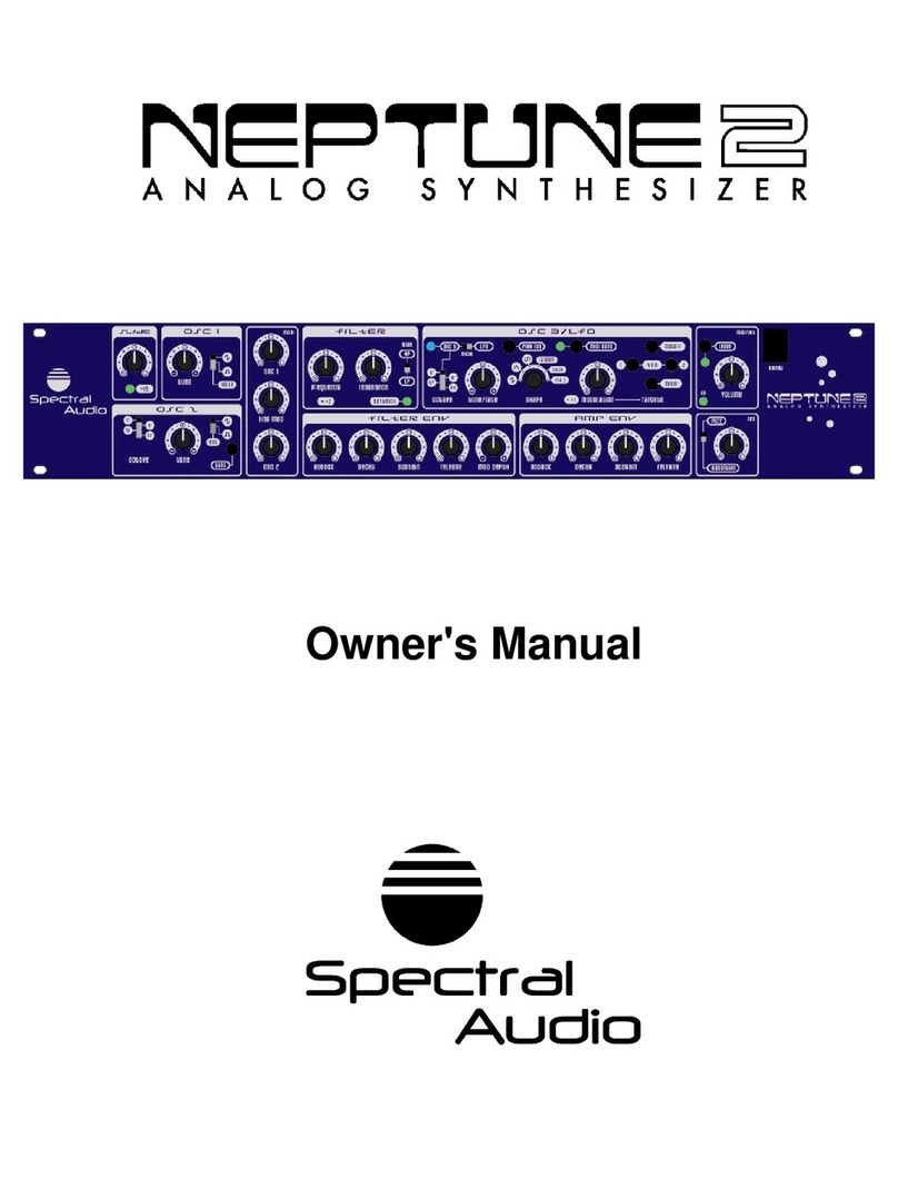
Spectral Audio Neptune 2 User manual

Service Manual

3DJH
Contents
1General Note............................................................................................................................................. 2
2Manual Changes....................................................................................................................................... 2
2.1Having pulse-width modulation (PWM) for the rectangular wave on OSC1..OSC3.......................... 2
2.1.1OSC1.......................................................................................................................................... 2
2.1.2OSC2.......................................................................................................................................... 2
2.1.3OSC3.......................................................................................................................................... 2
2.2OSC3/LFO sync with OSC1 or OSC2............................................................................................... 3
2.3Even faster envelopes....................................................................................................................... 3
2.4Increase the tuning range for OSC1..OSC3...................................................................................... 3
2.5General in/outputs............................................................................................................................. 3
2.5.1Oscillators................................................................................................................................... 3
2.5.2Envelopes................................................................................................................................... 3
2.5.3Filter............................................................................................................................................ 3
2.5.4Distorter...................................................................................................................................... 4
2.5.5VCA............................................................................................................................................ 4
3Assembly plan Analogue Print (see also separate .gif file at the homepage)........................................... 5
4Assembly plan Digital Print ....................................................................................................................... 6
5Adjustment ................................................................................................................................................ 6
5.1Adjustment of 12.000 V Supply......................................................................................................... 6
5.2CV slope adjustment ......................................................................................................................... 6
5.3Osc1.................................................................................................................................................. 6
5.4Osc 2................................................................................................................................................. 6
5.5Osc 3................................................................................................................................................. 7
5.6Filter................................................................................................................................................... 7
5.7Noise generator................................................................................................................................. 7

3DJH
1General Note
Fully schematic is not supported by this manual. If you think you really need to receive it, please write to
spectralaudio@swissonline.ch.
2Manual Changes
2.1Having pulse-width modulation (PWM) for the rectangular wave on
OSC1..OSC3
2.1.1 OSC1
Open B1 with a sharp cutter.
2.1.2 OSC2
Open B2 with a sharp cutter.
Pictures shows Backside of the PCB.
2.1.3 OSC3
Open B3 with a sharp cutter.

3DJH
The square Pad is now the DC Signal input for PWM. It ranges from –3.8V to 2.3V for 0% to 100%PWM or you
if want to use the range 50% to 100% (the 0% to 50% do sound exactly the same), -0.75V to 2.3V.
2.2OSC3/LFO sync with OSC1 or OSC2
For this, connect a 470pF capacitor (it may be ceramic) from TP19 (OSC1 out) or TP45 (OSC2 out) to TP46
(you may want to use a switch).
2.3Even faster envelopes
To increase even more speed of EG1 (Volume), you may solder a resistor in the value of 100 Ohm down to 10
Ohm from the middle pin of Release Pot to TP50. For the VCF Envelope use TP44. Both may be result in some
click noise because of the low rise and decrease time of the Envelope.
2.4Increase the tuning range for OSC1..OSC3
It is possible to reduce the value of R001 for OSC1, R022 for OSC2 and R128 for OSC3. Its standard value is
1M5. Decreasing its value may also mean to decrease of R002, R021 and R129 to have the reference note in
the middle of the Tune Pot. To learn another Reference Note over MIDI is another solution but this decreases
the note range.
2.5General in/outputs
2.5.1 Oscillators
The easiest way to get the signals of the Oscillators are the switches SW02, SW03 and SW11. Amplitude is 0 to
+9V. Same for the noise generator.
2.5.2 Envelopes
These signals can be taken on ENV MOD potentiometer for the filter envelope and on the Volume potentiometer
for the VCA envelope.
2.5.3 Filter
The Filter input is at C18 and its output is U07 pin 14. Control voltage is applied to the Base of T05 and R073.
You can also access this voltage from the backside at this track below the resonance potentiometer:

3DJH
2.5.4 Distorter
The filter output is directly connected to the distorter/fuzzer selection input. Remove pin 14 from U07 from the
solder pad (leave it in the air and connect R105 to it). The remaining pad is now the input for the distorter/fuzzer
selection.
Output is at U05 pin 7.
2.5.5 VCA
Input is R026 (sold it away from the output of U05 pin 7). Output is pin 12 from U06 and at the output jack on the
rear side. Control voltage can be applied to the volume potentiometer.

3DJH
3Assembly plan Analogue Print (see also separate .gif file at the
homepage)

3DJH
4Assembly plan Digital Print
5Adjustment
Keep the following sequence.
5.1Adjustment of 12.000 V Supply
Connect a precise DVM to R031 and Ground (i.e. casing of octave select switch Osc2) and adjust TR501 to
12.000V after a warm-up phase of at least 30 minutes.
5.2CV slope adjustment
Connect a precise DVM to the output jack of CV. Adjust TR500 to 3.00V between C1–C4 (input over MIDI).
5.3Osc1
The offset for VCO1 is set with TR01 and the oscillator slope with TR02. Nonlinearity in the upper frequency
range is adjusted with TR03.
Proceed as follows to make the adjustment:
1. Set the MIDI reference note to C1 by pressing the learn-key.
2. Press key A3 and set the VCO1 frequency with offset trimmer to 220.0 Hz, measured with an exactly
frequency meter.
3. Press key A1 and set the frequency to 55.0 Hz with oscillator slope trimmer.
4. Repeat steps 2 and 3 until frequency values are stable.
5. Press the key A5 and set the frequency to 880.0 Hz with nonlinearity trimmer.
6. Repeat steps 2 to 5 and re-adjust if necessary.
5.4Osc 2
Same as above but with TR04 as offset, TR05 as oscillator slope and TR06 as nonlinearity correction. Do it first
with Oct switch in 16' pos and correct later the Nonlinearity pot with Oct switch in the highest position until no
beats are hear able to Osc 1.

3DJH
5.5Osc 3
Same as above but with TR07 as offset, TR08 as oscillator slope and TR09 as Nonlinearity correction. Do it first
with Oct switch in 32' pos. Now all frequencies are half the value of the above. Correct later the Nonlinearity pot
with Oct switch in the highest position until no beats are hear able to Osc 1.
5.6Filter
Put it in self resonation (start of). Set key follow switch to 100%. Measure the generated frequency and set Cut-
off pot to 100Hz with C1 at MIDI input. Input now C4 at MIDI and adjust TR10 to 800 Hz. Repeat if necessary.
5.7Noise generator
Read out the output with an Oscilloscope at the wave select switch. Adjust TR11 to maximum amplitude whitout
climps.
~~~
Have fun!
Other manuals for Neptune 2
1
Table of contents
Other Spectral Audio Synthesizer manuals
