SPECTRO Inc. M90301 User manual

Operation & User Manual
Source Frequency
Test Meter
Part Number M90301

Part Number M90301
Operation & User Manual
Source Frequency
Test Meter

© 2008-2012 Spectro, Incorporated. All rights reserved.
The information and descriptions in this document are the sole property of Spectro Incorporated and may
not be copied, reproduced, disseminated, or distributed without explicit written permission from Spectro
Incorporated. The statements, configurations, technical data, and recommendations in this document
are believed to be accurate and reliable at the time of this publication, but Spectro Incorporated assumes
no responsibility or liability for any errors or inaccuracies that may appear in this document. Spectro
Incorporated is not responsible for any infringement of patents or other rights of third parties that
may result from the use of this document. The content of this document is furnished for informational
purposes only, is subject to change without notice, and does not represent a commitment or guaranty
by Spectro Incorporated. Spectro Incorporated makes no warranty, express or implied, with respect to
the content of this document. Spectro Incorporated shall not be liable for any loss or damage, including
consequential or special damages, resulting from any use of this information, even if loss or damage is
caused by Spectro Incorporated as a result of negligence or any other fault.
FluidScan is a registered trademark and SpectroInc, Spectroil, SpectroVisc, SpectroTrack, SpectroLNF,
SpectroFTIR, and SpectroFDM are trademarks of Spectro, Incorporated. All other trademarks are the
property of their respective holders.
Spectro Incorporated (“Spectro Inc.”) warrants to the original purchaser only, that all Spectro Inc. bench top
instruments will be free from defects in material or workmanship for a period of twelve (12) months from
date of installation or fifteen (15) months from the date of shipment, whichever occurs first. SPECTRO
INC.’S SOLE OBLIGATION AND YOUR EXCLUSIVE REMEDY under this Limited Warranty and, to
the extent permitted by law, any warranty or condition implied by law, shall be the repair or replacement of
parts, without charge, which are defective in material or workmanship and which have not been misused,
carelessly handled, abnormal conditions or operation, accidents or acts of God, or misrepaired by persons
other than Spectro Inc. or Authorized Service Provider. To make a claim under this Limited Warranty, you
must contact the Spectro Inc. Factory Service Center or Authorized Service Provider. The determination of
whether any product has been subject to misuse or abuse will be made solely by Spectro Inc. If a hardware
defect arises and a valid claim is received within the limited warranty period, at its option and to the extent
permitted by law, Spectro Inc. will either (1) repair the hardware defect at no charge, using new parts or
refurbished parts that are equivalent to new in performance and reliability, or (2) exchange the product with
a product that is new or refurbished that is equivalent to new in performance and reliability and is at least
functionally equivalent to the original product. Spectro Inc. may request that you replace defective parts with
user-installable new or refurbished parts that Spectro Inc. provides in fulfillment of its warranty obligation.
A replacement product or part, including a user-installable part that has been installed in accordance
with instructions provided by Spectro Inc., assumes the remaining warranty of the original product. For
Authorized Service Provider, please contact Spectro Inc. Technical Support, +1-978-431-1130, or support@
spectroinc.com.

IMPORTANT!
Register Your Product.
Register your product online at http://www.spectroinc.com/register.htm.
Filling out the online form completes your product registration. Completing the one-page form is quick and
enables Spectro to:
• Contact you with important product alerts.
• Inform you about any product updates.
• Send special product-based applications as they become available.
• Obtain needed information for processing a warranty claim.


Source Frequency Test Meter v July 2012/Version 1.2
Product Safety
WARNING: High voltages are present during the operation of the Spectroil M!
Observe all safety precautions! Turn OFF the main power switch and unplug the
Spectroil M before performing any work.
Software CAUTION: Do not attempt to add any software or alter the original
factory-installed software without checking first with the Spectro Inc. Service
Department.

Product Safety Operation & User Manual
July 2012/Version 1.2 vi Source Frequency Test Meter

Contents
1.0 INTRODUCTION ......................................................................................................... 1
2.0 DESCRIPTION & SPECIFICATIONS.......................................................................... 3
3.0 MAINTENANCE & ADJUSTMENT ............................................................................ 5
3.1 Display Contrast Adjustment ........................................................................................... 5
3.2 Battery Replacement ........................................................................................................5
3.3 Calibration ....................................................................................................................... 6
4.0 PROCEDURE TO CHECK THE EXCITATION SOURCE FREQUENCY.................. 7
4.1. Auxiliary Gap Optical Fiber View..................................................................................... 7
4.2 Auxiliary Gap Direct View ............................................................................................... 9
5.0 DETAILED DESCRIPTION OF EXCITATION SOURCE FREQUENCY ................. 13
Source Frequency Test Meter
|
| vii
July 2010/Version 1.2

List of Effective Pages
is manual consists of 18 pages plus a cover.
Summary of SFTM Manual Versions
Change Ver- Date Description
First Issue 1.0 30 June 1995 CID versions of the Spectroil M and Spectroil Jr+
1 1.1 29 July 2008 Updated manual for current versions of the Spectroil M
that have SFTM docking ports.
viii
|
| Operation & User Manual
July 2010/Version 1.2

Section 1.0
Introduction
1.0 INTRODUCTION
is manual provides a description of the Source
Frequency Test Meter (SFTM) and step-by-step
procedure to measure and adjust the excitation
source frequency of the Spectroil M family of Oil
Analysis Spectrometers. Proper care and opera-
tion of the Source Frequency Test Meter (SFTM),
part number M90300 and information on the
maintenance and adjustments to the SFTM are
also provided.
e Source Frequency Test Meter (SFTM) Figure
1-1, is a hand-held electronic measurement device
used to check the frequency of oscillatory arc exci-
tation sources. e SFTM is easy to operate, it is
battery operated, requires no calibration, and can
be used in place of an oscilloscope. It is shipped
in its own carrying case and includes the four AA
batteries required for operation.
e excitation sources in all versions of the
Spectroil M are an oscillatory arc discharge. ey
have been designed to achieve excitation charac-
teristics that produce a spectral signature to match
the United States Department of Defense Joint
Oil Analysis Program (JOAP) date base. e per-
Figure 1-1, Source Frequency Test Meter
(SFTM) in its carrying case
Source Frequency Test Meter
|
| 1
July 2010/Version 1.2

formance of the Spectroil M is directly dependent
on the output characteristics and frequency of the
oscillatory arc source.
It is absolutely necessary to check the excitation
source frequency prior to performing the JOAP
monthly correlation samples. e source frequen-
cy also has to be checked each time the instrument
is deployed to a country where the line frequency
is other than 60 Hertz, and/or to verify that no
damage was incurred during transport.
Description and user maintenance of the SFTM
is provided in Sections 2 and 3 of this manual.
Step-by-step procedures for setting the excitation
source frequencies of the Spectroil M are provided
in Section 4.0 and a detailed description of the
excitation source frequency and the need to verify
it is explained in Section 5.
2
|
| Operation & User Manual
July 2010/Version 1.2

2.0 DESCRIPTION & SPECIFICATIONS
e Source Frequency Test Meter is a hand-held
device used to check and to verify the excitation
source frequency of the Spectroil M family of
oil analysis spectrometers. It includes its’ own
carrying case the four AA batteries required for
operation. A special adapter is pre-installed for
connection to the SFTM port on Spectroil M
spectrometers.
e SFTM control buttons used in measuring
excitation source frequency, are noted in Figure
2-1. e step-by-step procedure for checking the
excitation source frequency of a Spectroil M is de-
scribed in Section 4.0 of this manual.
Section 2.0
Description &
Specifications
Input Coupler / Aiming Light
Momentary Power Switch
MEMORY Switch
CONTRAST Control
Figure 2-1, Source Frequency Test Meter
(SFTM)
Source Frequency Test Meter
|
| 3
July 2010/Version 1.2

SFTM SPECIFICATIONS
Item Description
Display: 5 digits, 10 mm (0,4”) Liquid Crystal (LCD)
Measuring Range: 5 to 99,999 counts
Resolution: 0.1 count ( < 1,000 discharge/min.
1 discharge/min. (> 1,000 counts)
Accuracy: +/- (0.05% + 1 count)
Time Base: Quartz Crystal, 4.194 Mhz
Operating Temperature: 0-50°C (32 - 122°F)
Memory: Last/Maximum/Minimum values
Battery: Four 1.5 volt AA batteries
Power Consumption: Approximately 153 ma
Size: 165 x 61 x 39 mm (6.5 x 2.4 x 1.5 inch)
Weight: 235 g (0.52 LB) including batteries
4
|
| Operation & User Manual
July 2010/Version 1.2

Section 3
Maintenance &
Adjustment
3.0 MAINTENANCE & ADJUSTMENT
3.1 Display Contrast Adjustment
e contrast of the LCD display may vary due
to battery voltage drop or a change of the viewing
angle. e contrast is variable with the “CON-
TRAST” adjustment knob on the control panel
of the SFTM. It should be set for viewer prefer-
ence.
3.2 Battery Replacement
e LCD display will have a “LO” indication to
warn the user that the batteries are low and should
be replaced. e warning appears when the bat-
teries have discharged from the original 6.0 volts
to approximately 4.5 volts. When the “LO” in-
dication rst appears, the SFTM can still be used
for several hours, however, it is good practice to
replace the batteries at the rst opportunity.
e battery compartment, Figure 3-1 is on the
back of the SFTM. e battery compartment
Table 3-1, SFTM battery compartment with
cover removed
Source Frequency Test Meter
|
| 5
July 2010/Version 1.2

cover can be removed by momentarily depressing
the latch with your nger. Replace the old batter-
ies with four (4) fresh AA batteries. e correct
polarity and location of the batteries is shown in
each socket. All four batteries should be replaced
at the same time. Replace the cover by lining
up the bottom slots and closing until a “click” is
heard to signify that it is latched.
3.3 Calibration
e Source Frequency Test Meter does not require
calibration with normal use. e discharge rate is
counted and controlled by a 4.194 MHz quartz
crystal similar to a quartz watch.
Under normal circumstances, the SFTM does not
require calibration. To verify calibration, point
the SFTM toward a uorescent light xture and
press and hold the Momentary Power Switch for
at least 10 seconds. For power sources with 60
Hertz, the meter should read 7,200 +/- 100 and
for 50 Hertz power sources, 6,000 +/- 100. If the
SFTM measurement exceeds the tolerances speci-
ed, utilize the oscilloscope method.
Contact Spectro Inc. if you suspect that your
SFTM has been abused and/or its operation is
suspect.
6
|
| Operation & User Manual
July 2010/Version 1.2

4.0 PROCEDURE TO CHECK THE
EXCITATION SOURCE FREQUENCY
ere are two methods to check the excitation
source frequency using the Source Frequency Test
Meter. e rst method employs an optical ber
that views the arc discharges as they occur across
the auxiliary gap. e second method measures
the source frequency by directly viewing the arc
discharges that occur across the auxiliary gap.
Both methods work equally well, but the advan-
tage of the rst method is that it is faster and also
does not expose the operator to areas with live
voltage. Follow the steps listed below to check
the excitation source frequency using the SFTM.
4.1. Auxiliary Gap Optical Fiber View
To check the excitation source frequency by mea-
suring the discharges per minute across the auxil-
iary gap using the SFTM, follow the steps listed
below.
NOTE: is procedure should be performed by the
operator once per month prior to JOAP monthly
correlations, whenever the instrument is moved, or
every 2,000 burns.
1. Remove the SFTM from the protective con-
tainer. If this is the rst time this test meter
is to be used, four AA size batteries will have
to be installed before it can be operated.
ese batteries are provided with the test
meter.
2. Hold the SFTM in the right hand and with
your thumb, press and hold the momentary
switch located on the upper right side of the
SFTM. is will turn the test meter ON
and along the right side of the digital display
a “0” (zero) should appear. If the image of
the “0” is not clear, or if many characters
simultaneously appear on the display, the
CONTRAST control should be adjusted.
NOTE: Under normal circumstances, the SFTM
does not require calibration. To verify calibration,
Section 4
Procedure
to Check the
Excitation
Source
Frequency
Source Frequency Test Meter
|
| 7
July 2010/Version 1.2

point the SFTM toward a uorescent light xture
and press and hold the Momentary Power Switch
for at least 10 seconds. For power sources with 60
Hertz, the meter should read 7,200 +/- 100 and
for 50 Hertz power sources, 6,000 +/- 100. If the
SFTM measurement exceeds the tolerances specied,
utilize the oscilloscope method.
3. Remove the threaded protective dust cover
from the SFTM PORT and insert the dock-
ing coupler of the SFTM into the SFTM
PORT until it stops. e SFTM coupler
has a guide so that it can only be inserted at
a convenient viewing angle. Refer to Figure
4-1.
4. Set the MODE switch on the control panel
to OPERATE.
NOTE: Make four warm-up burns before proceed-
ing.
5. Prepare the sample excitation stand for a
routine analysis with a new disc and rod
electrode and set the analytical gap in ac-
cordance with the Spectroil M Operator’s
Manual. Place a sample holder on the
sample table and ll it with base oil (0 ppm)
standard oil. Raise the sample holder into
the normal position. Close the sample stand
door.
6. Press the START switch located on the front
control panel. e burn cycle will begin and
the high voltage across the auxiliary gap will
appear as a concentrated stream of light. In
actuality, this steam of light consists of ap-
proximately 700 high voltage discharges per
second and the function of the SFTM is to
detect and quantify these arc discharges.
7. Press and hold the momentary power switch
on the SFTM after the preburn period
has completed (after approximately 6 sec-
onds). If the SFTM is properly positioned
to receive the light emitted across the aux-
iliary gap, a small red light emitting diode
(LED) located above the digital display of
the SFTM will begin to ash at a consistent
rate. Hold the position of the SFTM steady
and continue to hold the momentary power
switch and monitor the consistency of the
red LED to ensure that the signal is strong
and consistent. Once the burn cycle is com-
plete (30 seconds), release the momentary
power ON switch of the SFTM and remove
the SFTM from the port for a more conve-
nient observation of the measurement.
NOTE: It is normal to observe uctuations of
approximately +/- 1000 discharges per minute
(DPM) during the measurement cycle.
NOTE: If the red LED does not appear or ashed
at an erratic rate, the SFTM is not in position to
permit the light from the auxiliary gap to enter the
test meter. Repeat the procedure until a steady ash-
ing red light is obtained.
8. When the burn is complete, press and hold
the MEMORY switch located on front of
the SFTM one time. A number will appear
momentarily, then the letters “LA” (last)
will appear. is number should be ap-
proximately 54,000 and represents the last
measurement the SFTM made before the
power switch was released. is reading is
not signicant for this procedure. Release
the MEMORY switch to end the reading.
9. Press and hold the MEMORY switch a
second time and a new number will ap-
pear. is is the number that will be used to
Table 4-1, SFTM inserted in SFTM port and
ready for use
8
|
| Operation & User Manual
July 2010/Version 1.2

determine the excitation source frequency.
is number must be 54,000 +/- 2000. If
the MEMORY switch is held, the letters
“UP” will appear, which designates that
this was the highest reading taken during
the burn. If the source frequency is within
this range, then proceed to step 12 of this
procedure. If not, SFTM port ber may be
defective. Check frequency with the Direct
View Method, Section 4.2.
10. Upon completion of the source frequency
check, replace the dust cover on the SFTM
PORT to prevent any accumulation of
debris.
11. Return the SFTM to its protective storage
container.
12. is procedure is now complete.
4.2 Auxiliary Gap Direct View
To check the excitation source frequency by mea-
suring the discharges per minute across the auxil-
iary gap using the SFTM, follow the steps listed
below.
WARNING: is procedure should only be per-
formed by a qualified technician.
1. Remove power from the Spectroil M by
placing the main power circuit breaker CB1
to the OFF or down position, Figure 4-2.
2. Remove the four Phillips head mount-
ing screws positioned in the corners of the
Spectroil M top trim panel, Figure 4-2. Be
sure not to lose the dress washers for these
panel screws; they are not captive to the
screws. Remove the top trim panel.
3. To remove the top excitation source access
panel (the smaller of the two panels) Figure
4-3, turn the six 1/4 turn pawl fasteners
screws counterclockwise until the maximum
travel of the screw is achieved, approximately
10 rotations.
CAUTION: Do not overdrive the counterclock-
wise travel of these screws, stop when light resis-
tance is encountered. Once all fasteners have been
loosened, remove the top access panel.
NOTE: is panel has a safety interlock switch to
protect unauthorized personnel from removing this
panel with power applied. Only trained operators
and electronic maintenance personnel are autho-
rized to enter this compartment. To perform service
in the excitation source compartment, the operator/
technician must bypass this safety interlock switch.
4. To bypass the interlock switch, Figure 4-4,
grasp the plunger and pull in an upward
direction until the plunger moves approxi-
mately 1/4 inch. is will bypass the inter-
Table 4-2, Location of CB1 and top trim panel
Table 4-3, Excitation source access panel
Circuit Breaker CB1
Excitation
Source
Access Panel
Top Trim Panel
Source Frequency Test Meter
|
| 9
July 2010/Version 1.2

lock switch function and permit power to be
applied to the instrument. If either of two
safety interlock switches are not properly
positioned or bypassed, circuit breaker CB1
will fail to latch in the ON position.
5. Place the circuit breaker CB1 in the up
or ON position. is will apply power to
the instrument and after the computer has
loaded the software and selected the proper
line voltage and frequency settings for the
current location, a burn can be made.
NOTE: Make four warm-up burns before proceed-
ing..
6. Prepare the sample excitation stand for a
routine analysis with a new disc and rod
electrode and set the analytical gap in ac-
cordance with the Spectroil M Operator’s
Manual. Pour a new sample of base (0 ppm)
standard and place this sample in position
for analysis. Close the sample stand door.
7. Set the MODE switch on the control panel
to OPERATE.
8. Remove the SFTM from the protective con-
tainer. If this is the rst time this test meter
is to be used, four AA size batteries will have
to be installed before it can be operated.
ese batteries are provided with the test
meter.
9. Hold the SFTM in the right hand and with
your thumb, press and hold the momentary
switch located on the upper right side of the
SFTM, see Figure 4-5. is will turn the
test meter ON and along the right side of
the digital display a “0” (zero) should ap-
pear. If the image of the “0” is not clear, or
if many characters simultaneously appear on
the display, the CONTRAST control should
be adjusted.
NOTE: Under normal circumstances, the SFTM
does not require calibration. To verify calibration,
point the SFTM toward a uorescent light xture
Safety
Interlock
Switch
Auxiliary
Gap
Table 4-4, Location of safety interlock and auxiliary gap
10
|
| Operation & User Manual
July 2010/Version 1.2
and press and hold the Momentary Power Switch
for at least 10 seconds. For power sources with 60
Hertz, the meter should read 7,200 +/- 100 and
for 50 Hertz power sources, 6,000 +/- 100.
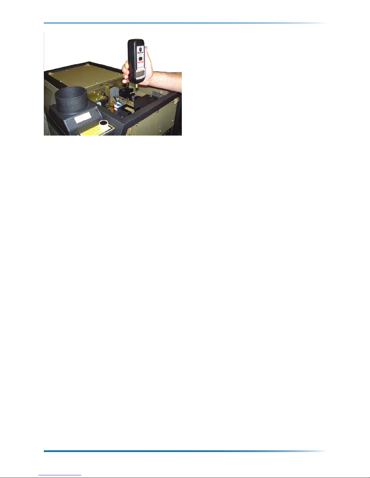
10. Locate the auxiliary gap on the excitation
source component board, refer to Figure 4-4
for the location. Hold the SFTM approxi-
mately 10 inches (25 cm) above the auxiliary
gap with the input coupler pointing down-
wards towards the auxiliary gap as shown in
Figure 4-5.
Once the burn cycle begins, high voltage will be
generated and distributed throughout the excita-
tion source. Do not touch any components of
the excitation source assembly while the excita-
tion source is operating. Wait until the burn
cycle terminates before attempting to make any
adjustments. Always turn the MODE switch to
STANDBY before making any adjustments.
Warning: Wear safety glasses or do not look di-
rectly at the spark. e spark from the auxiliary
gap could harm your eyes if stared at for pro-
longed periods of time.
Caution: Only trained personnel should carry
out this procedure. It is performed in an area of
the Spectroil M where high voltage potentials are
present.
11. Press the START switch located on the
front control panel, refer to the Spectroil M
Operator’s Manual. e burn cycle will be-
gin and the high voltage across the auxiliary
gap will appear as a concentrated stream of
light. In actuality, this steam of light consists
of approximately 700 high voltage discharg-
es per second and the function of the SFTM
is to detect and quantify these arc discharges.
12. Press and hold the momentary power
switch on the SFTM after the preburn
period has completed (after approximately
6 seconds). If the SFTM is properly posi-
tioned to receive the light emitted across the
auxiliary gap, a small red light emitting di-
ode (LED) located above the digital display
of the SFTM will begin to ash at a consis-
tent rate. Hold the position of the SFTM
steady and continue to hold the momentary
power switch and monitor the consistency
of the red LED to ensure that the signal is
strong and consistent. Once the burn cycle
is complete (30 seconds), release the mo-
mentary power ON switch of the SFTM
and position it so it can be easily read.
NOTE: It is normal to observe uctuations of
approximately +/- 1000 discharges per minute
(DPM) during the measurement cycle.
If the red LED does not appear or ashed at an
erratic rate, the SFTM is not in position to permit
the light from the auxiliary gap to enter the test
meter. Repeat the procedure until a steady ash-
ing red light is obtained.
13. When the burn is complete, press and hold
the MEMORY switch located on front of
the SFTM one time. A number will appear
momentarily, then the letters “LA” (last)
will appear. is number should be ap-
proximately 54,000 and represents the last
measurement the SFTM made before the
power switch was released. T his reading is
not signicant for this procedure. Release
Table 4-5, Auxiliary gap assembly and ideal
position for source frequency test
Source Frequency Test Meter
|
| 11
July 2010/Version 1.2
Table of contents


