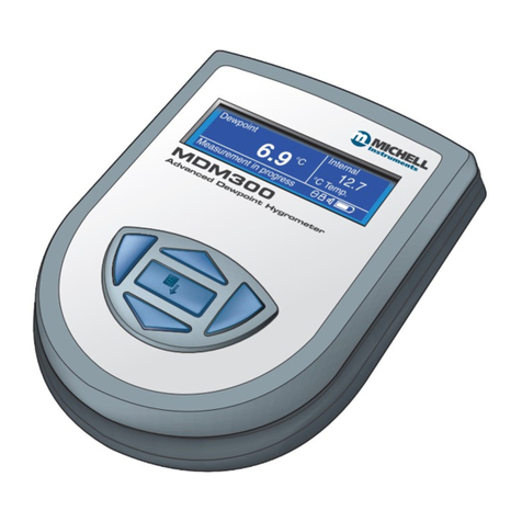
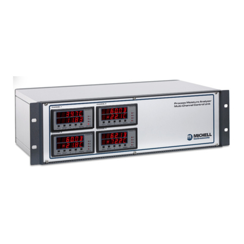
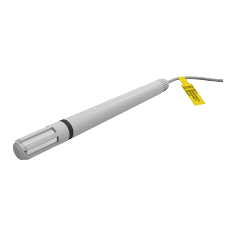
PST Michell Instruments Pura Advanced Online 2 User manual

Pura
Advanced Online 2 Hygrometer
User Manual
97628 Issue 1
January 2023

Please ll out the form(s) below for each instrument that has been purchased.
Use this information when contacting Michell Instruments for service purposes.
Product Name
Order Code
Serial Number
Invoice Date
Installation Location
Tag Number
Product Name
Order Code
Serial Number
Invoice Date
Installation Location
Tag Number
Product Name
Order Code
Serial Number
Invoice Date
Installation Location
Tag Number

© 2023 Michell Instruments
This document is the property of Michell Instruments Ltd and may not be copied or
otherwise reproduced, communicated in any way to third parties, nor stored in any Data
Processing System without the express written authorization of Michell Instruments Ltd.
Pura Advanced Online 2 Hygrometer
For Michell Instruments' contact information please go to
www.ProcessSensing.com

Pura Advanced Online 2 Hygrometer Manual
iv 97628 Issue 1, January 2023
Contents
Safety ................................................................................................................................vi
Electrical Safety ..........................................................................................................vii
Pressure Safety ...........................................................................................................vii
Hazardous Materials (WEEE, RoHS3 & REACH) ..............................................................vii
Repair and Maintenance ..............................................................................................vii
Calibration ..................................................................................................................vii
Safety Conformity .......................................................................................................vii
Abbreviations .................................................................................................................... viii
1 INTRODUCTION ................................................................................................1
1.1 Features ............................................................................................................ 1
2 INSTALLATION ..................................................................................................2
2.1 Unpacking the Instrument ................................................................................... 2
2.1.1 Unpacking Pura Advanced Online 2 Hygrometer .............................................. 2
2.1.2 Unpacking Pura SEN (transmitter, no block version) ......................................... 3
2.1.3 Unpacking Pura OEM-single bag, PRM-double bag versions .............................. 4
2.1.4 Unpacking the Process Monitor ...................................................................... 4
2.2 Pura Advanced Online 2 Components ................................................................... 5
2.3 Process Monitor Display ...................................................................................... 6
2.3.1 Process Monitor Display Layout ...................................................................... 6
2.3.2 Electrical Connections .................................................................................... 7
2.3.2.1 High-Voltage Power Supply Input ................................................................... 8
2.3.2.2 Low-Voltage Power Supply Input (Alternative) ................................................. 8
2.3.2.3 Dew-Point Sensor Modbus RTU over RS485 Digital Input (Required) ................ 9
2.3.2.4 Pressure Sensor Input (Optional) ................................................................... 9
2.3.2.5 Analog Outputs ............................................................................................. 9
2.3.2.6 Modbus RTU Output ...................................................................................... 9
2.3.2.7 Relay Outputs ............................................................................................. 10
2.3.2.8 Transmitter Connections .............................................................................. 10
2.4 Mounting the Process Monitor ........................................................................... 11
2.5 Pura SEN ......................................................................................................... 11
2.6 Pura OEM, PRM ................................................................................................ 12
2.6.1 Pura M12 Connector Version ........................................................................ 12
2.6.1.1 Electrical Connections .................................................................................. 13
2.6.1.2 Pura M12 Cables ......................................................................................... 14
2.6.2 Cable Selection for Self-Assembled Cables ..................................................... 14
2.7 Transmitter Mounting ........................................................................................ 14
2.7.1 Pura SEN - Sample Block (Optional) ............................................................ 14
2.7.2 Pura OEM & PRM Connection ....................................................................... 16
2.7.3 Pura SEN - Direct Pipeline Connection........................................................... 17
3 OPERATION ....................................................................................................18
3.1 Process Monitor Conguration ........................................................................... 18
3.2 Front Panel Conguration Menu Access .............................................................. 18
3.3 Conguration Menu Explained ........................................................................... 20
3.4 Setting Up the Process Monitor Conguration ..................................................... 21
3.4.1 Alarms Conguration ................................................................................... 21
3.4.2 Analog Outputs Conguration ...................................................................... 24
3.4.3 Display Conguration .................................................................................. 26
3.4.4 Input Conguration ..................................................................................... 27
3.4.5 Pressure Conguration ................................................................................ 29
3.4.6 About Menu ................................................................................................ 30

Pura Advanced Online 2 Hygrometer Manual
Michell Instruments v
Figures
Figure 1 Unpacking – Monitor and Pura SEN, no block version ....................................2
Figure 2 Unpacking – Monitor and Pura OEM / PRM ...................................................3
Figure 3 Unpacking – Pura OEM & PRM – Single / Double Bag ....................................4
Figure 4 Pura Advanced Online 2 Components ...........................................................5
Figure 5 Monitor Display in Normal Operation ............................................................6
Figure 6 Electrical Wiring Schematic..........................................................................8
Figure 7 Pura SEN .................................................................................................11
Figure 8 Pura OEM, PRM ........................................................................................12
Figure 9 Sensor Connector Installation ....................................................................13
Figure 10 Sensor Block Connection ...........................................................................15
Figure 11 Inlet/Outlet Identication ..........................................................................16
Figure 12 Electrical Wiring Schematic........................................................................21
Figure 13 Alarm Conguration Screen Explained ........................................................21
Figure 14 Analog Outputs Conguration Screen Explained ..........................................24
Figure 15 Display Conguration Screen Explained ......................................................26
Figure 16 Input Conguration Screen Explained .........................................................27
Figure 17 Installation Location .................................................................................33
Figure 18 Installation Location .................................................................................33
Figure 19 Material Permeability Comparison ..............................................................35
Figure 20 Dead volume ............................................................................................36
Appendices
Appendix A Technical Specications .............................................................................. 39
A.1 Transmitters ................................................................................39
A.2 Monitors ..................................................................................... 41
Appendix B Process Monitor Register Map .....................................................................44
Appendix C Quality, Recycling & Warranty Information ................................................... 54
Appendix D Return Document & Decontamination Declaration ........................................ 56
4 MAINTENANCE ................................................................................................31
4.1 Maintenance and Calibration ............................................................................ 31
4.2 Fault Conditions ............................................................................................... 31
5 MEASUREMENT GUIDE ....................................................................................32
5.1 Sampling Considerations ................................................................................... 32
5.2 Sampling Hints ................................................................................................. 35

Pura Advanced Online 2 Hygrometer Manual
vi 97628 Issue 1, January 2023
Safety
The instrument is designed to be completely safe when installed and operated correctly in accordance
with the information provided in this manual.
This manual contains all the required information to install, operate and maintain this product. Prior
to installation and use of this product, this entire manual should be read and understood. Installation
and operation of this product should be carried out by suitably competent personnel only. The
installation and operation of this product must be in accordance with the instructions provided and
according to the terms of any associated safety certicates. Incorrect installation and use of this
product other than those described in this manual and other than its intended purpose will render
all warranties void.
This product meets the essential protection requirements of the relevant EU & UK directives. Further
details of applied directives may be found in the product specication.
Electricity and pressurized gas can be dangerous. This product must be installed and operated only
by suitable trained personnel.
!
No user serviceable parts inside
!
Where this hazard warning symbol appears in the following
sections, it is used to indicate areas where potentially hazardous
operations need to be carried out and where particular attention to
personal and personnel safety must be observed.
Where this symbol appears in the following sections it is used to
indicate areas of potential risk of electric shock.
This product is intended for use only under the following conditions:
a. indoor use
b. altitude up to 2 000 m
c. temperature 5 °C...40 °C
d. maximum relative humidity 80 % for temperatures up to 31 °C decreasing
linearly to 50 %, relative humidity at 40 °C
e. MAINS supply voltage uctuations up to ±10 % of the nominal voltage
f. TRANSIENT OVERVOLTAGES up to the levels of OVERVOLTAGE CATEGORY ll
g. TEMPORARY OVERVOLTAGES occurring on the MAINS supply
h. applicable POLLUTION DEGREE 2 of the intended environment

Pura Advanced Online 2 Hygrometer Manual
Michell Instruments vii
Electrical Safety
Ensure electrical safety is complied with by following the directions provided here and observing all
local operation & installation requirements at the intended location of use.
This product is completely safe when using any options and accessories supplied by the manufacturer
of this product for use with it. Refer to Section 2 (Installation) of this manual for further details.
Pressure Safety
For this product to operate satisfactorily, pressurized gas must be connected to it. Observe all the
information contained within this manual and all local operation & installation requirements at the
intended location of use. Refer to Section 2 (Installation) of this manual for further details.
Hazardous Materials (WEEE, RoHS3 & REACH)
This product does not contain or release any prohibited chemicals listed on the SVHC (Substances
of Very High Concern) Candidate List. During the intended normal operation of this product it is not
possible for the user to come into contact with any hazardous materials. This product is designed to
be recyclable except where indicated.
Repair and Maintenance
The instrument must be maintained either by the manufacturer or an accredited service agent. For
contact information visit the website at www.ProcessSensing.com.
Calibration
Periodic re-calibration is recommended in order to maintain the highest quality of measurement
in your application. Michell Instruments recommends that you have your Pura M12 transmitter re-
calibrated annually unless it is used in a mission-critical application or in a contaminated environment,
in which case the calibration interval should be reduced accordingly.
Michell Instruments can oer a variety of re-calibration and exchange transmitter schemes to suit
your specic needs. A local representative will be pleased to provide detailed custom advice.
Safety Conformity
This product meets the essential protection requirements of the relevant EU & UK directives. Further
details of applied standards may be found in Appendix C.

Pura Advanced Online 2 Hygrometer Manual
viii 97628 Issue 1, January 2023
Abbreviations
The following abbreviations are used in this manual:
AC alternating current
atm pressure unit (atmosphere)
barg pressure unit (=100 kP or 0.987 atm)
ºC degrees Celsius
ºF degrees Fahrenheit
DC direct current
dp dew point
ft foot (feet)
g gram(s)
Hz Hertz
“ inch(es)
lb pound
l/min liters per minute
m meter(s)
µm micro-meter
mA milliampere
max maximum
min minute(s)
MPa megapascal (Pascals x106)
Nl/min normal liters per minute
Nm Newton meter
ppmV parts per million (by volume)
rh relative humidity
scfh standard cubic feet per hour
V Volts
Ω Ohms

Pura Advanced Online 2 Hygrometer Manual
Michell Instruments 1
INTRODUCTION
1 INTRODUCTION
The Pura Advanced Online 2 Hygrometer is easy to install and congure; this versatile
touch screen hygrometer can measure and display dew point and moisture content and
indicate pressure. This display provides analog, digital and 4 programmable relay alarm
outputs with front screen or software app display conguration.
It has been developed as a premium-performance hygrometer system for use in a wide
variety of applications.
It can display data in °C or °F dew point, ppmV
, lb/mmscf or g/m3, from -120 up to -40 °C
(-184 up to -40 °F), at pressures up to 240 bar (3481 psi).
To calculate moisture content from dew point, it is necessary to know the system pressure.
This hygrometer can either compensate for pressure change by using a live pressure
sensor input, or accept a xed pressure input value.
1.1 Features
The Pura Advanced Online 2 Hygrometer oers customers the following features:
• Measures down to -120 °Cdp (-184 °Fdp) (1 ppbV)
• Stable and repeatable measurement
• Fast response
• Economical and advanced monitor solutions
• Dew-point or moisture content output
• 4...20 mA and Modbus RTU over RS485 outputs
• Traceable 7-point calibration certicate
• 1/2”, 1/4” male VCR process connections
• M12 electrical connectors
• Sensor exchange program

Pura Advanced Online 2 Hygrometer Manual
297628 Issue 1, January 2023
INSTALLATION
2 INSTALLATION
!
It is essential that the connection of electrical and gas supplies
to this instrument be undertaken by competent personnel.
2.1 Unpacking the Instrument
2.1.1 Unpacking Pura Advanced Online 2 Hygrometer
The Pura instruments and accessories are packed into a box and the method of unpacking
is shown as follows:
Figure 1
Unpacking – Monitor and Pura SEN, no block version
NOTE: Packaging specications are subject to continuous improvement, as
we reduce our use of plastics and move to cardboard packing systems.

Pura Advanced Online 2 Hygrometer Manual
Michell Instruments 3
INSTALLATION
Figure 2
Unpacking – Monitor and Pura OEM / PRM
2.1.2 Unpacking Pura SEN (transmitter, no block version)
Unpack the dew-point transmitter from the rectangular cardboard box.
NOTE: The transmitter sensing element is protected while in transit by a red
cover containing a small desiccant capsule. This plastic item is not required
for the operation of the transmitter.
NOTE: Keep the electrical connector in a safe place until the transmitter is
ready for wiring.

Pura Advanced Online 2 Hygrometer Manual
497628 Issue 1, January 2023
INSTALLATION
2.1.3 Unpacking Pura OEM-single bag, PRM-double bag versions
Figure 3
Unpacking – Pura OEM & PRM – Single / Double Bag
2.1.4 Unpacking the Process Monitor
The Process Monitor is packed in a cardboard box, together with its xing clamps.

Pura Advanced Online 2 Hygrometer Manual
Michell Instruments 5
INSTALLATION
2.2 Pura Advanced Online 2 Components
On delivery please check that all the following standard components are present in the
packing box. Report any shortages to Michell Instruments, immediately.
Figure 4
Pura Advanced Online 2 Components
1. PURA Monitor
2. Clamps
3. Sensor cable assembly
4. Pura Transmitter (SEN) OR
Pura Transmitter (OEM) or (PRM)
Leak test certicate included
5. Screwdriver
6. Calibration certicate

Pura Advanced Online 2 Hygrometer Manual
697628 Issue 1, January 2023
INSTALLATION
2.3 Process Monitor Display
The display within the Process Monitor is an LCD 320 x 240 pixel software driven, touch
screen color display.
2.3.1 Process Monitor Display Layout
In normal operation, the display screen will appear as below.
The display shows a moisture or pressure value, the status of four alarms and a display
locked/unlocked symbol, which is all explained in detail in
Figure 5
below.
2
1
3
4
1Dew Point or Moisture Content value referenced to its congured scale
2Pressure Indication value or ppmV referenced to its congured pressure scale
3Alarm Status of the 4 relay outputs
4Security code protected Unlock button to access the conguration menu
Figure 5
Monitor Display in Normal Operation

Pura Advanced Online 2 Hygrometer Manual
Michell Instruments 7
INSTALLATION
2.3.2 Electrical Connections
Electrical connections to the Pura Advanced Online 2 system are as follows:
• AC power supply input, 85...265 V AC (7.5 VA)
• Alternative low-voltage DC input is also available: 18...28 V DC (170 mA
@ 24 V DC)
• Dew-Point Sensor Modbus RTU over RS485 digital input (24 V DC loop
power provided by monitor)
• Pressure Sensor 2-wire 4...20 mA current loop (24 V DC loop power
provided by monitor) input (optional)
• Modbus RTU over RS485 digital communications interface
• 3 x programmable 4...20 mA analog outputs for assigning to dew point,
moisture content and pressure parameters
• 2 x Form A, 2 x Form C Namur compliant programmable relay outputs for
process and fault conditions
The power supply voltage is indicated on the connection detail label located on the
Process Monitor. As the Process Monitor is provided for continuous operation, it does
not have an ON/OFF switch.
The power supply to the Process Monitor may be one of the following, dependent on
the type ordered.
NOTE: Connect 0 V to local or remote Earth depending upon installation.

Pura Advanced Online 2 Hygrometer Manual
897628 Issue 1, January 2023
INSTALLATION
2.3.2.1 High-Voltage Power Supply Input
Figure 6
Electrical Wiring Schematic
For high-voltage powered display
• 85...265 V AC 50/60 Hz
It is essential that the connection of electrical supplies to this
instrument is undertaken by competent personnel.
Connect the power supply to the monitor as shown in
Figure 6
above.
PIN 14 – Earth
PIN 15 – Neutral
PIN 16 – Live
2.3.2.2 Low-Voltage Power Supply Input (Alternative)
For low-voltage DC powered display
• 18...28 V DC
Connect the power supply to the DC version Process Monitor as shown in
Figure 6
above.
PIN 15 – 0V DC
PIN 16 – 18...28 V DC

Pura Advanced Online 2 Hygrometer Manual
Michell Instruments 9
INSTALLATION
2.3.2.3 Dew-Point Sensor Modbus RTU over RS485 Digital Input (Required)
For AC or DC voltage powered display version
Connect the Dew-Point Sensor to the Process Monitor as shown in
Figure 6
.
PIN 1 – +24 V DC Power
PIN 2 – RS485 A digital comms
PIN 3 – RS485 B digital comms
PIN 6 – 0 V DC Power
2.3.2.4 Pressure Sensor Input (Optional)
For AC or DC voltage powered display version
Connect the Pressure Sensor to the monitor as shown in
Figure 6
.
PIN 4 – +24 V DC Power
PIN 5 – 4...20 mA signal return
PIN 6 – 0 V DC Power
2.3.2.5 Analog Outputs
For AC or DC voltage powered display version
PIN 7 – 4...20 mA Current Source Output 1
PIN 8 – 4...20 mA Current Source Output 2
PIN 9 – Common
PIN 10 – 4...20 mA Current Source Output 3
2.3.2.6 Modbus RTU Output
For AC or DC voltage powered display versions
PIN 11 – RS485A digital comms
PIN 12 – RS485B digital comms
PIN 13 – 0 V DC Power

Pura Advanced Online 2 Hygrometer Manual
10 97628 Issue 1, January 2023
INSTALLATION
2.3.2.7 Relay Outputs
For AC or DC voltage powered display versions, the relay outputs are as shown in
Figure 6
.
Alarms 1/2
PIN 17 – AL2 normally open
PIN 18 – Common
PIN 19 – AL1 normally closed
PIN 20 – AL1 normally open
Alarms 3/4
PIN 21 – AL4 normally open
PIN 22 – Common
PIN 23 – AL3 normally closed
PIN 24 – AL3 normally open
2.3.2.8 Transmitter Connections
Connect the Pura M12 dew-point sensor as shown in the table in
Figure 6
.

Pura Advanced Online 2 Hygrometer Manual
Michell Instruments 11
INSTALLATION
2.4 Mounting the Process Monitor
The Process Monitor is designed for panel mounting and requires a panel cut-out of 44
x 92 mm (1.73 x 3.62”). The recommended panel thickness is 2...5 mm (0.08...0.2”).
To mount the unit, proceed as follows:
1. Pass the Process Monitor through the front of the panel.
2. Support the Process Monitor and attach mounting xing brackets
onto the side of the monitor.
3. Tighten the xing screw nger tight, against the back of the panel.
Recommended maximum torque is 30 cNm using a 1.5 mm Allen
key.
4. Ensure that the Process Monitor is sitting ush to the front of the
panel and tighten the xing screws evenly against the back of the
panel.
Caution: Do not overtighten the screws as this could cause the case to crack.
2.5 Pura SEN
NOTE: For environmental and operating conditions, refer to Appendix A:
Technical Specications.
Electrical connector
Transmitter cover
Transmitter label
Hexagonal nut
Process connection (½”VCR)
Sensing element
Figure 7
Pura SEN
NOTE: M12 connector supplied.

Pura Advanced Online 2 Hygrometer Manual
12 97628 Issue 1, January 2023
INSTALLATION
2.6 Pura OEM, PRM
NOTE: For environmental and operating conditions, refer to Appendix A:
Technical Specications.
NOTE: The OEM and PRM transmitters are protected in transit by putting in a
plastic bag lled with nitrogen. The Pura OEM has single-bag protection and
the Pura PRM has double-bag protection.
Electrical connector
Transmitter cover
Transmitter label
Sensor block
Gas inlet (¼” VCR)
(see note below) Gas outlet
(¼” VCR)
NOTE: The Pura has a uni-directional connection and must be
connected so the upstream flow is connected to the inlet port
of the Pura block (marked with a silver label).
INLET
Figure 8
Pura OEM, PRM
NOTE: M12 connector supplied.
2.6.1 Pura M12 Connector Version
The following sections apply to the M12 connector version of the transmitter shown below.
Table of contents
Other PST Measuring Instrument manuals
PST
PST MA886 User manual

PST
PST Center 252 User manual
PST
PST MICHELL Instruments Easidew Advanced Online User manual
PST
PST Comet Commeter D4130 User manual
PST
PST MITCHELL S8000 -100 User manual

PST
PST Michell Instruments S8000 -100 User manual

PST
PST CENTER 24 User manual

PST
PST Michell Instruments XTP601 User manual
PST
PST MICHELL Instruments MDM300 User manual
PST
PST Michell Instruments TDL600 User manual

