Note: On InVision collaboration tables, (non-Access) the mount can be located in 2 different positions:
above the monitor for group teleconferencing, or below the monitor for face-to-face conferencing.
0112774R2 Page 4 of 6
Installation below monitor
1. Using two people, carefully lift the monitor off the monitor mount and set aside.
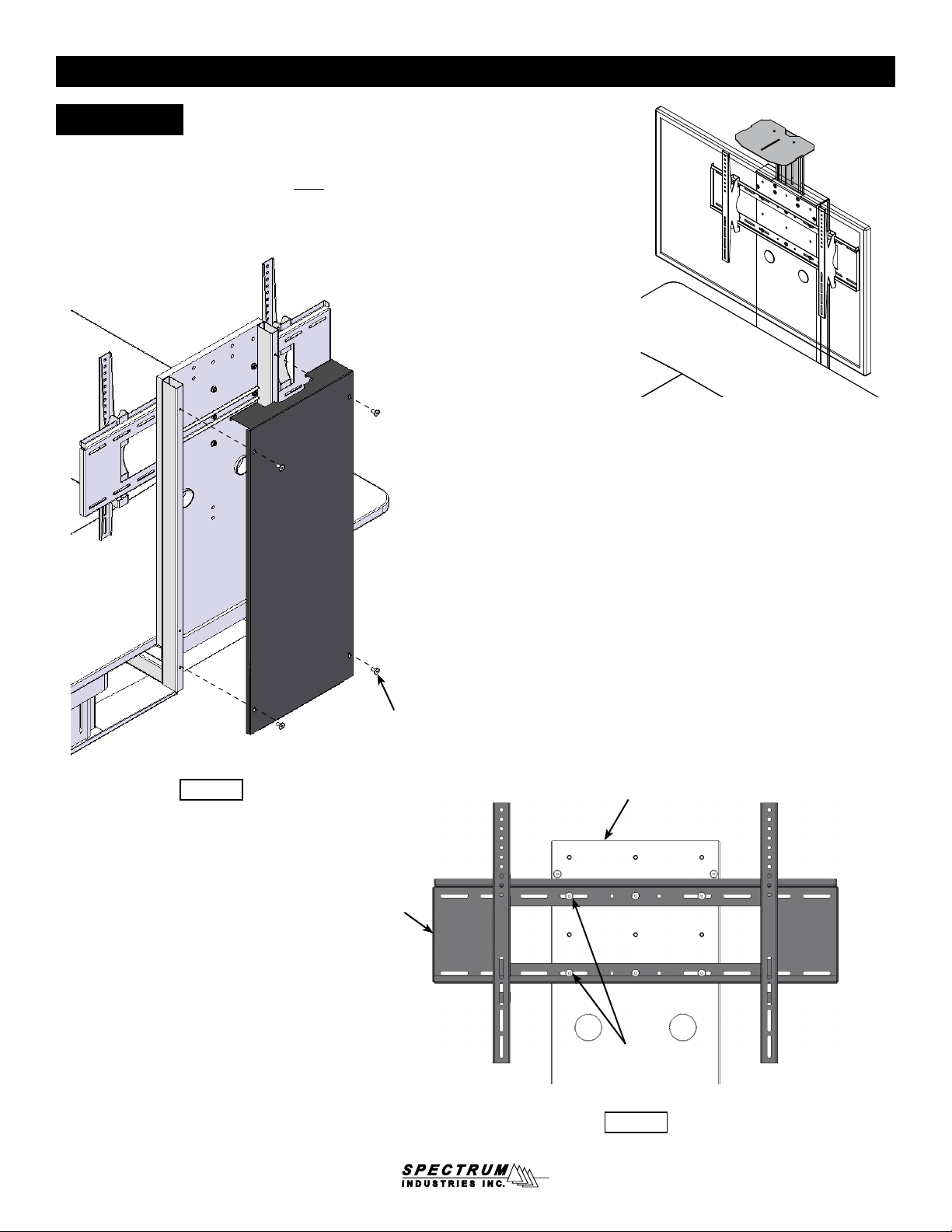
2. Remove the display stand back panel by removing the (6) 1/4-20 x 30mm JC bolts (retain bolts)
and set aside. Figure 2.
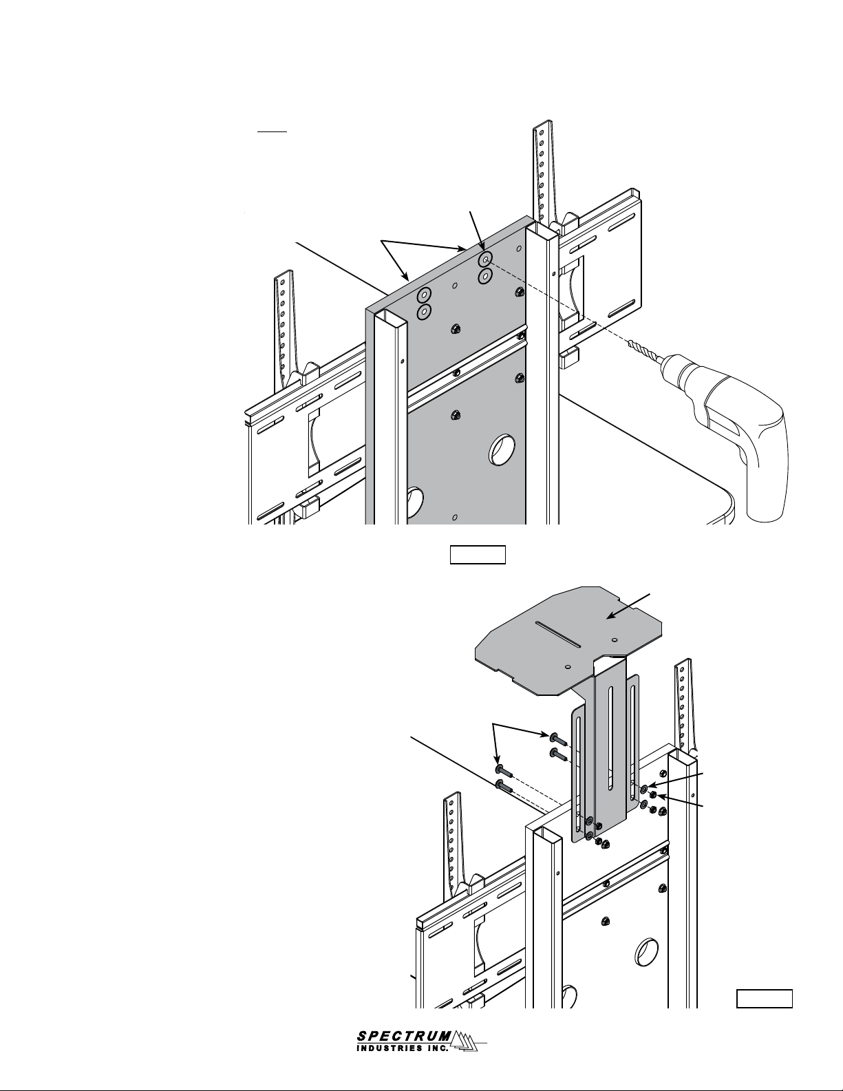
3. Locate the two 3/8” holes in the display stand front panel. These holes do not go all the way
through the panel so they will need to be drilled completely through.
4. Apply masking tape over the hole locations on the mount-side of the panel to minimize laminate
chip-out while drilling.
5. Using a drill with a sharp 3/8” drill bit, slowly drill through the panel at the two 3/8” hole locations.
Figure 3.
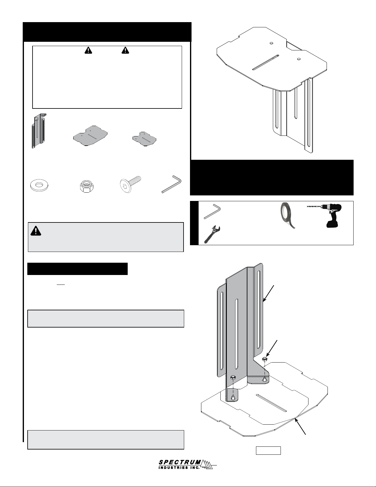
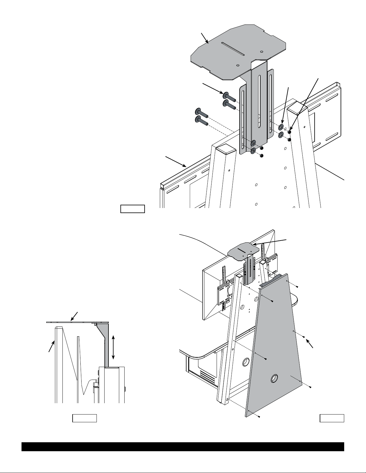
6. Orient the assembled camera mount as shown with the display stand front panel. Using the center
slot, align the shelf bracket with the two centered mounting holes and install (2) 1/4-20 x 30mm JC
bolts with (2) 1/4-20 locknuts (not shown) and (2) 1/4 washers (not shown) on the back. Figure 4.
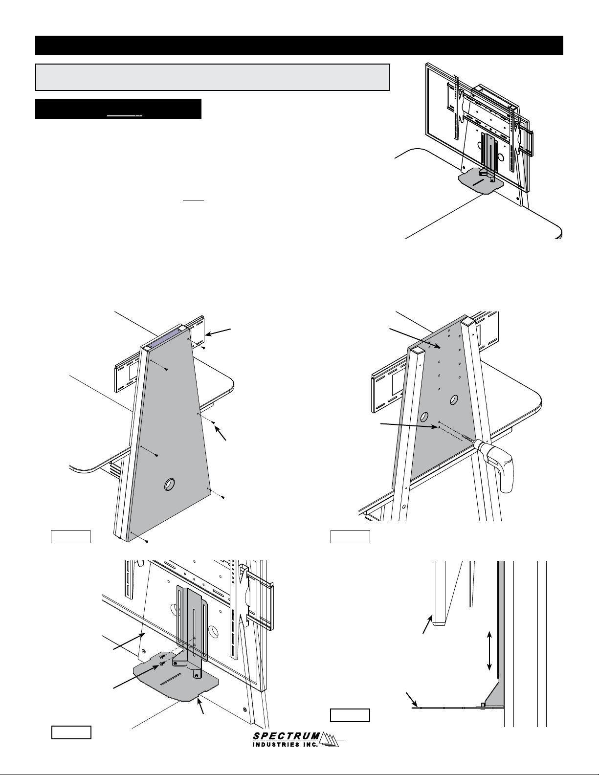
7. Carefully lift the monitor back onto the monitor mount.
8. Adjust the camera mount to sit below the installed monitor with enough clearance for your
camera, then tighten the bolts securely. Figure 5.
9. Install camera onto the shelf.
10. Route cords through the display stand front panel grommets.
11. After all electrical connections and wiring is complete, re-install the back panel with the (6) 1/4-20
x 30mm JC bolts and tighten securely.
InVision table with Display Stand
37106
Figure 4
Display stand
front panel
Assembled
camera mount
(2) 1/4-20 x 30mm JC bolts
with (2) 1/4 washers and
(2) 1/4-20 locknuts on back
Camera
mount
Adjust shelf
below monitor
Monitor
Figure 5
Figure 3
Display stand
front panel
(2) 3/8” holes
in panel
Drill with
3/8” drill bit
1/4-20 x 30mm
JC bolt
Display stand
back panel
Figure 2
Monitor
mount
InVision™Media Collaboration Table installation