SPEDIX S250 User manual


Drone It Yourself! consists of the following modules:
0. INTRODUCTION TO THE DRONETEAM PROJECT
1. BASIC TOY DRONE FRAME
2. MODULE OF FLIGHT CONTROL
3. MODULE OF COMMUNICATION CONTROL
4. MODULE OF ADVANCED FRAME
5. MODULE OF GPS-COMPASS CONTROL
6. MODULE OF PROBLEM MANAGEMENT
7. MODULE OF FLIGHT STABILIZATION SYSTEM
8. MODULE OF FIRST PERSON VIEW
9. DRONETEAM E-LEARNING PLATFORM
10. OTHER DEVELOPMENTS
11.GLOSSARY
This project has been funded with support from the European Commission.
This publication reflects the views only of the author, and the Commission
cannot be held responsible for any use which may be made of the information
contained therein.

0
MODULE OF
ADVANCED FRAME
2015-1-ES01-KA202-015925

DRONETEAM PROJECT NO.2015-1-ES01-KA202-015925
4.MODULE OF ADVANCED FRAME
1
Index
1. DRONE ADVANCED COMPONENTS ....................................................................................... 3
1.1. INTRODUCTION ............................................................................................................. 3
1.2. GPS ................................................................................................................................ 4
1.3. POWER MODULE........................................................................................................... 4
1.4. TELEMETRY.................................................................................................................... 4
1.5. FPV................................................................................................................................. 5
2. DRONE ADVANCED ASSEMBLY.............................................................................................. 6
2.1. INTRODUCTION ............................................................................................................. 6
2.2. KIT CONTENTS ............................................................................................................... 6
2.2.1. KIT S250 SPEDIX..................................................................................................... 6
2.2.2. EXTRA PROPELLERS BLACK 5X4.5 (CW / CCW)...................................................... 6
2.2.3. TURNIGY 9X 9CH & MODULE 8CH RECEIVER MODULE......................................... 7
2.2.4. BATTERY TURNIGY 2.2 AMPS 11.1V (3S) 1.5C....................................................... 7
2.2.5. BATTERY MULTISTAR 3.0 AMPS BATTERY 11.1V (3S) 20C .................................... 7
2.2.6. HOBBYKING® B3AC COMPACT CHARGER.............................................................. 8
2.2.7. APM KIT 2.6 ........................................................................................................... 8
3. ASSEMBLY.............................................................................................................................. 8
3.1. TOOLS FOR MOUNTING ................................................................................................ 8
3.2. MECHANICAL ASSEMBLY............................................................................................... 8
3.3. ELECTRONIC ASSEMBLY................................................................................................. 8
3.3.1. APM 2.6 vs CC3D ................................................................................................... 8
3.3.2. PRESET MOTORS ................................................................................................... 9
3.4. CONNECTION DIAGRAM (APM 2.6)............................................................................. 11
3.4.1. INPUTS PORT APM 2.6 (RECEIVER RC) ................................................................ 11
3.4.2. GPS ...................................................................................................................... 13
3.4.3. TELEMETRY.......................................................................................................... 14
3.4.4. POWER MODULE................................................................................................. 14
3.4.5. OUTPUT PORTS APM 2.6 (MOTORS)................................................................... 15
3.5. FINAL ASSEMBLY ......................................................................................................... 16
4. SETTING MISSION PLANNER................................................................................................ 16
4.1. BRIEF EXPLANATION ON THE FLIGHT MODES AND HOW THEY WORK. ..................... 22
5. CHECKS ................................................................................................................................ 23

DRONETEAM PROJECT NO.2015-1-ES01-KA202-015925
4.MODULE OF ADVANCED FRAME
2
6. PROPELLER COMPARATIVE ................................................................................................. 25
6.1. CALCULATIONS:........................................................................................................... 29
6.2. TESTS: .......................................................................................................................... 29
6.3. PREMISES AND CONCLUSIONS:................................................................................... 29
6.4. SPECIFICATIONS........................................................................................................... 30
6.5. FIRST TESTS.................................................................................................................. 31
6.6. MAKING A LAB MACHINE AND TESTING..................................................................... 31
7. PARTS OF A BASIC INJECTION MOULD AND HOW DOES IT WORK. .................................... 32
7.1. PARTS OF A BASIC INJECTION MOULD........................................................................ 34
7.2. THE MOST IMPORTANT PARTS ................................................................................... 34
7.3. OPERATION OF THE INJECTION OR FIXED PART.......................................................... 35
7.4. OPERATION OF THE INJECTION OR FIXED PART.......................................................... 35
7.5. OPERATION OF THE EJECTOR OR MOBILE PART ......................................................... 36
7.6. OPERATION OF THE EJECTOR OR MOBILE PART ......................................................... 37
8. CREATING DRONE PARTS ON A 3D PRINTER....................................................................... 37
8.1. INTRODUCTION ........................................................................................................... 37
8.2. MODELING................................................................................................................... 37
8.3. 3D PRINTERS................................................................................................................ 37
8.4. HOW TO ANALYZE A 3D PART? ................................................................................... 38
8.5. PRINT SETTINGS........................................................................................................... 38
8.6. ADVANCED PRINT SETTINGS ....................................................................................... 38
8.7. PREVIEW OF THE PART................................................................................................ 39
8.8. PART PRINTING............................................................................................................ 39
8.9. LANDING GEAR............................................................................................................ 40
8.10. CUSTOMIZATION..................................................................................................... 42
9. FLOATING DESIGN ............................................................................................................... 43
9.1. BASED ON ARCHIMEDES’ PRINCIPLE........................................................................... 43

DRONETEAM PROJECT NO.2015-1-ES01-KA202-015925
4.MODULE OF ADVANCED FRAME
3
1. DRONE ADVANCED COMPONENTS
1.1. INTRODUCTION
Learning about all drone components. You can find all the information about advanced
components.
The advanced components are those components that aren't necessary for a drone to fly, but
they make the flight experience better, as well as enabling the drone to perform scheduled
routes. That is why, for a basic drone, they don't usually incorporate these components, but for
advanced drones they are necessary. The advanced components that are usually incorporated
are: GPS, Magnetometer, Gyroscope and Barometer.
First eight components are necessary to have a Basic Drone that can fly. The last four
components are necessary to have an Advanced Drone with greater stability and greater flight
possibilities:
Download Poster. Link: http://www.droneteamproject.eu/results/download-area2/231-
posters-on-drone-components
(Available in DIN A0 and DIN A2)

DRONETEAM PROJECT NO.2015-1-ES01-KA202-015925
4.MODULE OF ADVANCED FRAME
4
1.2. GPS
GPS provides latitude, longitude. Combined with a Magnetometer (direction), Barometer
(elevation) Accelerometer (inertia), Gyroscope (position). It is needed for waypoint flying mode.
1.3. POWER MODULE.
Power module permit measure current consumption and provides a stable voltage. It allows
triggering a warning when battery is near of its capacity or there is a power problem.
1.4. TELEMETRY
Telemetry, is used to collect data from mounted sensors. The data flow is bidirectional: it can
send data about the flight to a Ground Station and send commands to the FC.

DRONETEAM PROJECT NO.2015-1-ES01-KA202-015925
4.MODULE OF ADVANCED FRAME
5
1.5. FPV
First Person View (FPV), allows viewing on a screen (e.g. smartphone) the view of the camera
mounted. The camera may be mounted on a gimbal system to move and stabilise it.
The First Person View FPV system or real-time vision from a screen that receives the images
from the drone camera is a system that consists of several components: the camera, the
transmission system, the video receiver and the vision screen. In addition to the main elements,
a drone can have a stabilising system of the camera, known as Gimbal. This system has the
function of stabilising the camera, avoiding that the own inclination of the drone in its
movements or the vibration of the motors can affect the quality of the images. In the most
advanced drones, it is possible for an operator to independently operate the camera by moving
the Gimbal system according to the needs. These cases are very interesting in the height
inspection, where the pilot drives the drone and the camera operator manages the Gimbal
camera.

DRONETEAM PROJECT NO.2015-1-ES01-KA202-015925
4.MODULE OF ADVANCED FRAME
6
2. DRONE ADVANCED ASSEMBLY
2.1. INTRODUCTION
The propellers could cause injuries, therefore the Quadcopter never should be used around
people or in situations where you can lose control and cause an accident that could hit a person
or cause material damages.
Never place the propellers in the Quadcopter to be sure of the direction of rotation of these
have been mounted and should to be controlled safely.
Never leave charging batteries unattended or exposed to direct sunlight.
Never allow the cell voltage of the battery drops below 3.3V in shock.
2.2. KIT CONTENTS
2.2.1. KIT S250 SPEDIX
2.2.2. EXTRA PROPELLERS BLACK 5X4.5 (CW / CCW)

DRONETEAM PROJECT NO.2015-1-ES01-KA202-015925
4.MODULE OF ADVANCED FRAME
7
2.2.3. TURNIGY 9X 9CH & MODULE 8CH RECEIVER MODULE
2.2.4. BATTERY TURNIGY 2.2 AMPS 11.1V (3S) 1.5C
2.2.5. BATTERY MULTISTAR 3.0 AMPS BATTERY 11.1V (3S) 20C

DRONETEAM PROJECT NO.2015-1-ES01-KA202-015925
4.MODULE OF ADVANCED FRAME
8
2.2.6. HOBBYKING® B3AC COMPACT CHARGER
2.2.7. APM KIT 2.6
3. ASSEMBLY
3.1. TOOLS FOR MOUNTING
•Allen Wrenches.
•Phillips screwdriver.
•Tweezers
•Double-sided adhesive foam sticker
3.2. MECHANICAL ASSEMBLY
For chassis assembling, we should follow the manual accompanying the kit SPEDIX.
3.3. ELECTRONIC ASSEMBLY
3.3.1. APM 2.6 vs CC3D
The main differences between these autopilots are:

DRONETEAM PROJECT NO.2015-1-ES01-KA202-015925
4.MODULE OF ADVANCED FRAME
9
At first glance it can be seen that APM 2.6 is a higher version to CC3D both hardware and
software. Thanks to the magnetometer and a barometer built 2.6 AMP control of two degrees
of freedom to our drone (Altitude and YAW), degrees of freedom that could not be controlled
with precision CC3D model are added. For the above and adding the GPS can say that this new
model allows flight in automatic mode, the CC3D big change that allowed only a manual flight.
3.3.2. PRESET MOTORS
IMPORTANT: Make sure the propellers are not placed before performing the following steps.
Unlike CC3D, must be pre-set motors for greater motor performance. To do this, connect each
motor with RC receiver channel 3 as shown in the following figure:
•Why channel 3 of the receiver?
This channel is transmitting the value of the transmitter stick corresponding to the throttle or
also known as gas, which is the value that allows us to give power to the motors.
A solution to streamline this process, may be the implementation of the next plate of simple and
quick installation:
Thus the final assembly would be:
It should be very careful with the wiring, all cables must be connected in the same sense of
colours, as shown in the image.
You can also make individually calibrated as shown in the picture, repeating the action in all
esc.

DRONETEAM PROJECT NO.2015-1-ES01-KA202-015925
4.MODULE OF ADVANCED FRAME
10
•Why does this procedure do?
The motors used for Spedix are called brushless motors. These motors work in conjunction with
an ESC (Electronic Speed Controller) and APM to control them.
The APM processes the value that sends the station and he sends it to the ESC to vary the speed
of the motors. As the value sent to the ESC is directly the value of the station, the motors must
be prepared to don´t start rolling just start moving the stick of the transmitter, so you change
the minimum value that begin move motors with this procedure.
Once we make these steps, the procedure is as follows (for connecting both ways):
•Connect a tricolored cable channel 8 RC receiver to the port channel 8 OUTPUTS APM
2.6. This will cause the receiver to work when the battery is connected.
•With the transmitter battery still connected and disconnected, the throttle stick will
move to its maximum position.
IMPORTANT: Be sure the propellers are not placed before the next step.
•Connect the battery, starting a small tune, followed by a short beep sounds.
•Move the throttle stick to a position about 25% of full throttle and leave it alone, two
short beeps and long will be heard, this indicates that the procedure was successful.
•Place the throttle stick to the minimum and carefully check the throttle stick moving the
motors begin to move about 25% of the value of the maximum throttle.
DRONETEAM PROJECT NO.2015-1-ES01-KA202-015925
4.MODULE OF ADVANCED FRAME
11
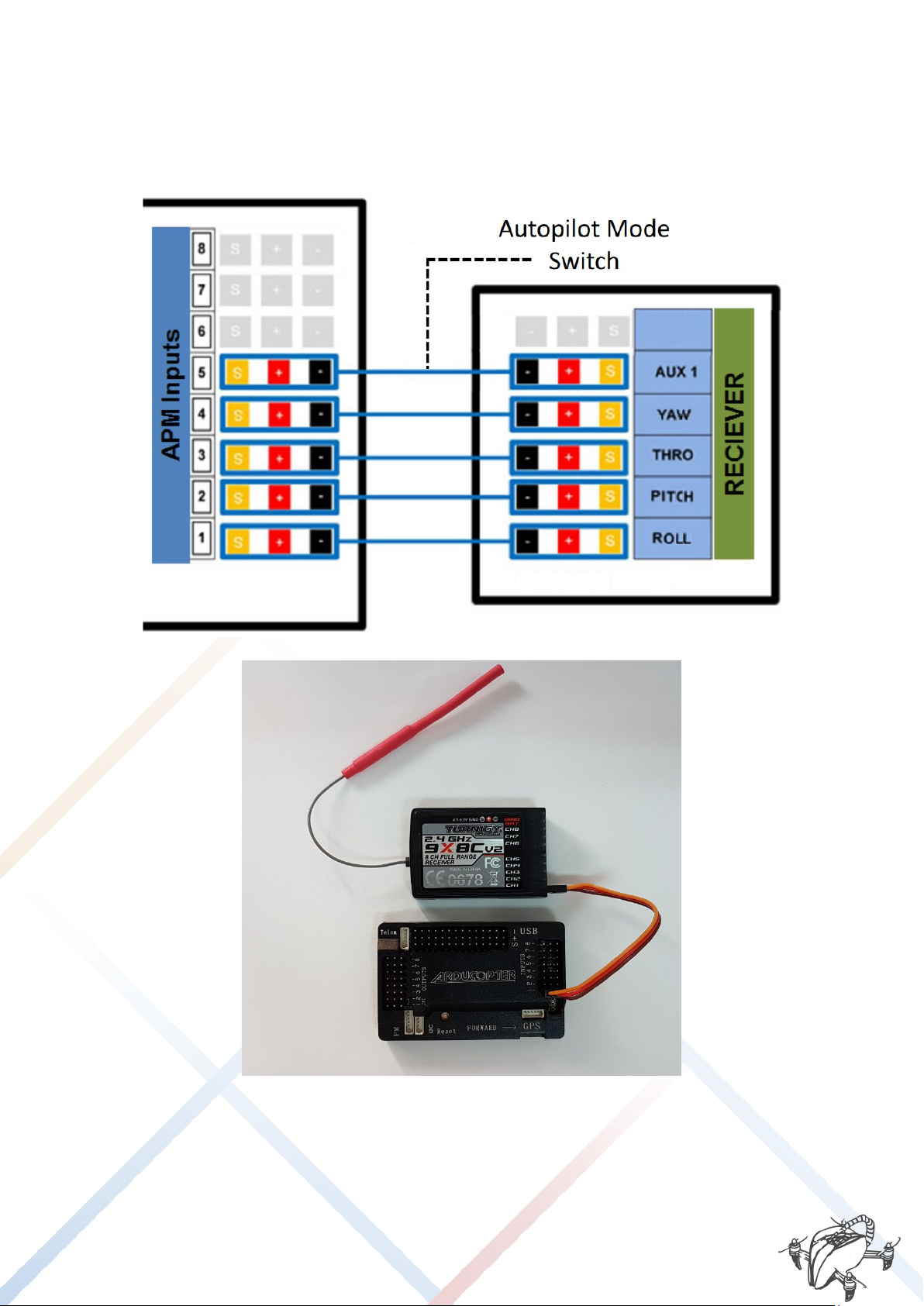
3.4. CONNECTION DIAGRAM (APM 2.6)
3.4.1. INPUTS PORT APM 2.6 (RECEIVER RC)
Connections between ArduPilot advanced controller (APM) and Drone Receiver:

DRONETEAM PROJECT NO.2015-1-ES01-KA202-015925
4.MODULE OF ADVANCED FRAME
12

DRONETEAM PROJECT NO.2015-1-ES01-KA202-015925
4.MODULE OF ADVANCED FRAME
13
3.4.2. GPS
The connector with 2 wires must be connected to the I2C port (Magnetometer) and formed by
4 in the GPS connector, as shown in the following figure:

DRONETEAM PROJECT NO.2015-1-ES01-KA202-015925
4.MODULE OF ADVANCED FRAME
14
3.4.3. TELEMETRY
Telemetry must be connected to the TELEM connector, as shown in the following figure:
3.4.4. POWER MODULE

DRONETEAM PROJECT NO.2015-1-ES01-KA202-015925
4.MODULE OF ADVANCED FRAME
15
The "Power module" must be connected to the PM connector as shown in the figure below, this
will allow us to know the battery voltage and ampere consumption of the motors.
3.4.5. OUTPUT PORTS APM 2.6 (MOTORS)

DRONETEAM PROJECT NO.2015-1-ES01-KA202-015925
4.MODULE OF ADVANCED FRAME
16
3.5. FINAL ASSEMBLY
For correct mounting Spedix APM is it important to define the position in which certain
components are placed.
(TAKE CARE TO THE RIGHT ADDRESSES AND MAGNETOMETER APM)
Once finished both electronic/mechanic assembly, it is suggested for the flight as follows:
4. SETTING MISSION PLANNER
For optimal configuration of your drone, you can download the files from DroneTeam eLearning
Platform (access from DroneTeam Webpage: http://www.droneteamproject.eu/ )
Mission Planner is a platform created for configuring certain autopilots (ArduPilot, PixHawk ...)
open source and free. Allow the configuration and monitoring for our autopilot data received
from this.
•Connect your APM to the PC.
•Start the program, it is important do not update the program, although it is
recommended, but this is a stable and fault-free software.

DRONETEAM PROJECT NO.2015-1-ES01-KA202-015925
4.MODULE OF ADVANCED FRAME
17
IMPORTANT: Make sure the blades are not placed before performing the following steps.
•In the upper right corner, a tab like the one shown below is appreciated. You must select
the device to be connected (or Telemetry APM):
or If the device to be connected is your APM, you must select the option that reads
"Arduino Mega 2560" and the secondary option "115200".
or If the device to be connected is the telemetry AutoPilot, you must select the
appropriate port, in our case "Silicon Labs USB to UART CP210x" and the secondary
option, select "57600".
•Press the "CONNECT" button.
A tab as the following, which first if everything is correct "DONE" will appear and then load a set
of returning parameters. Wait until the tab disappears.
If an error occurs, it will start a countdown, to solve this problem, try the following solutions:
or Reconnect the device and try again.
or Make sure that the connection settings are correct.
or restart the program.
If everything is correct it will show the main screen again, this time showing real-time data
AutoPilot.
•In the left upper, click "INITIAL SETUP". the screen will refresh and a small menu with 4
options appear. Click on "Install Firmware".
Table of contents
Other SPEDIX Drone manuals


