Speed Merchant Speed Spec Pan Sedan User manual
Congratulations on your purchase of a Speed Merchant
SpeedSpec 2 competition chassis.
This instruction manual will detail the specific steps involved to
build your new car. Make sure to take your time when building,
since even though there are very few parts in this kit, it is
important to make sure that everything is smooth (metal parts
such as kingpins, pivot balls, etc are polished, and that nothing
binds) and working the way they should. This will make
noticeable difference in the handling of the car out on the track.
Required tools and supplies:
.050” Hex driver
1/16” Hex driver
3/32” Hex driver
5/64” Hex driver
3/16” Nut driver
¼” Nut driver
3/32” Nut driver
File
Cyanoacrylate Glue
(CA or super glue)
35 Wt. Shock Oil (recommended)
Tube Spooge (damper tube lube)
1/8” and 3/32” Drill bits
82° countersink
Metal polish
Double sided tape (servo tape)
Ruler
Pen or pencil
Additional required parts:
540 sized electric motor
Electronic Speed Controller
Radio Transmitter
Radio Receiver
Servo (standard sized)
Servo saver
(to match servo brand)
4 Cell Sub-C size
NiMh or Ni Cad Battery
Tires and Wheels
Body shell
Paint for body shell
Speedspec2 - 0.0.2

2
Chassis prep:
Shown here is the chassis top and
chassis bottom. Note that the chassis
bottom has countersunk holes. To
prep this chassis you will need to file
the battery slots to keep from cutting
the insulation labels on the batteries.
This will also allow the battery pack to
sit lower in the chassis, lowering the
center of gravity.
top
bottom
When filing the slots, file from the top
side of the chassis with the file at a 45°
angle. Have an assembled 4-cell battery
pack handy to check depth as the
chassis is filed. Removing too much
material will allow the battery pack to sit
too low and could rub on the ground in
high speed corners.
After filing, the slots should look something like
the illustration to the right. If you filed the slots
too low and the battery sits lower than the
bottom of the chassis, they can be built back up
slowly using multiple layers of thick
cyanoacrylate (CA) glue.
Next assemble the chassis
components, using 4-40 x 3/8” flat
head screws (x10) (smr2012),
4-40 thin hex nuts (x6) (smr2077),
4-40 threaded stand-offs (x4).
Tip: use a little blue thread lock on
all metal to metal fasteners.
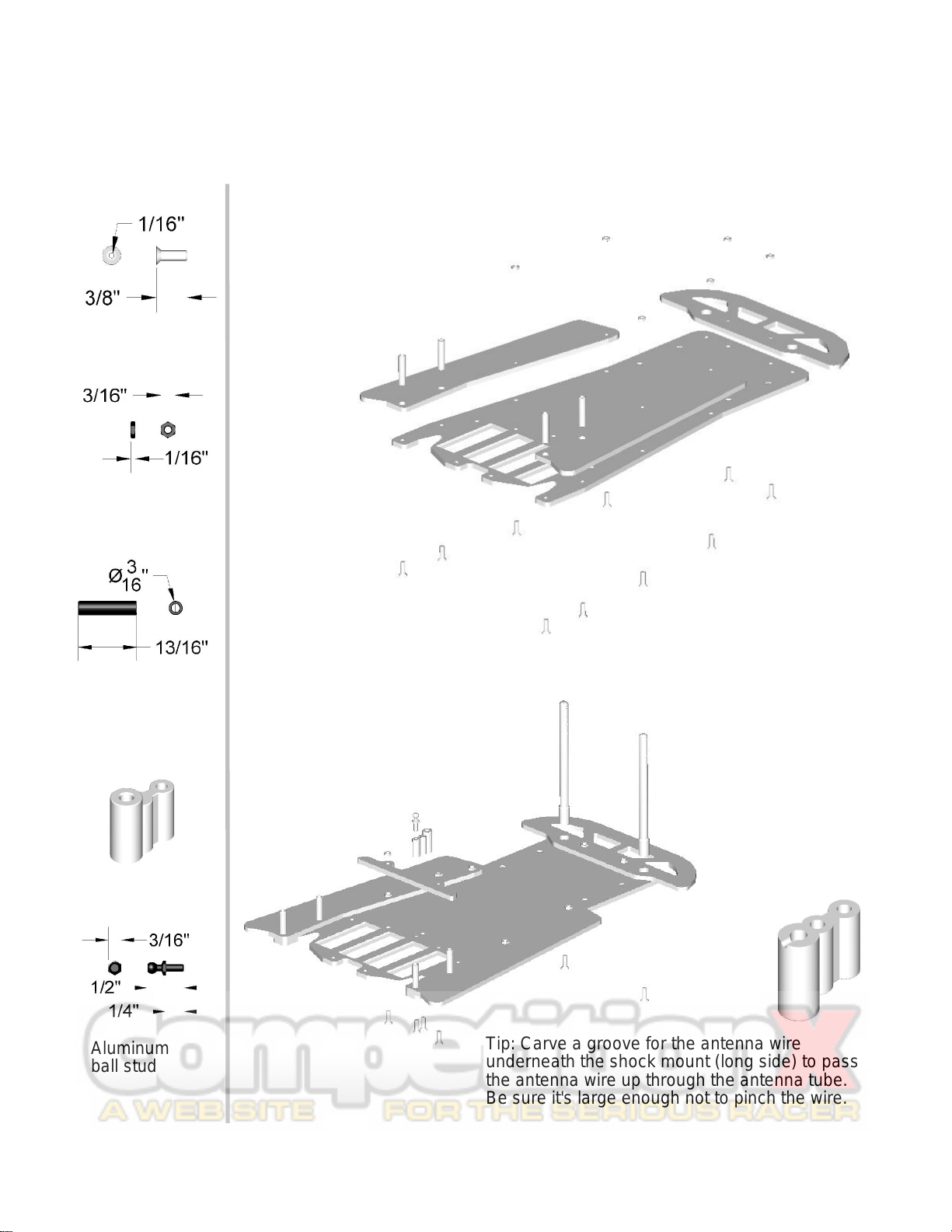
Continue assembly adding
battery positioning plate
using 4-40 x 3/8” flat head
screws (x2) (smr2012) and
4-40 small hex nuts (x2)
(smr2076). Attach the
antenna mount (smr1432)
and front body mounts
(smr1551) to the chassis
using 4-40 x 3/8” flat head
screws (x2). Install 4-40
aluminum ball stud into rear
of the antenna mount using
a little CA glue to secure it.
4-40 x 3/8”
flat head
4-40 hex nut
small
Tip: Carve a groove for the antenna wire
underneath the shock mount (long side) to pass
the antenna wire up through the antenna tube.
Be sure it's large enough not to pinch the wire.
Antenna/shock
mount
Tweak plate
and battery
strap stand-off
Aluminum
ball stud

4
Assemble the center pivot plate
with the pivot socket set
(smr1268), in the configuration
shown, fastening with 2-56 x 1/4”
button head screws (x2).
Attach to the chassis 4-40 x 1/2” flat head screws (x2) (smr2014) with 4-40 hex
nuts (x2) (smr2078). Slide center pivot assembly onto the 4-40 screws and
secure with 4-40 lock nuts (x2) (smr2082).
Attach the left and right bulkheads to the lower pod plate with 4-40 x 1/4”
flat head screws (x5) (smr2010).
2-56 x 1/4”
button head Pivot plate (smr1514)
2-56 x 1//4” (smr2060)
Suspension ball
Pivot socket - lower
(smr1269)
Pivot socket - upper
(smr1269)
4-40 x 1/2”
flat head
4-40 large
locknut
4-40 large
hexnut
4-40 x 1/4”
flat head
5
Attach rear pod to the main
chassis using a 4-40 x 1/2” flat
head screw (smr2014). Use a low
roll center cone (SMR5008) on
top of the lower pod plate,
screwing through the 1/4” x 4-40
suspension ball in the center
pivot. Secure with 4-40 mini-
locknut (SMR2080).
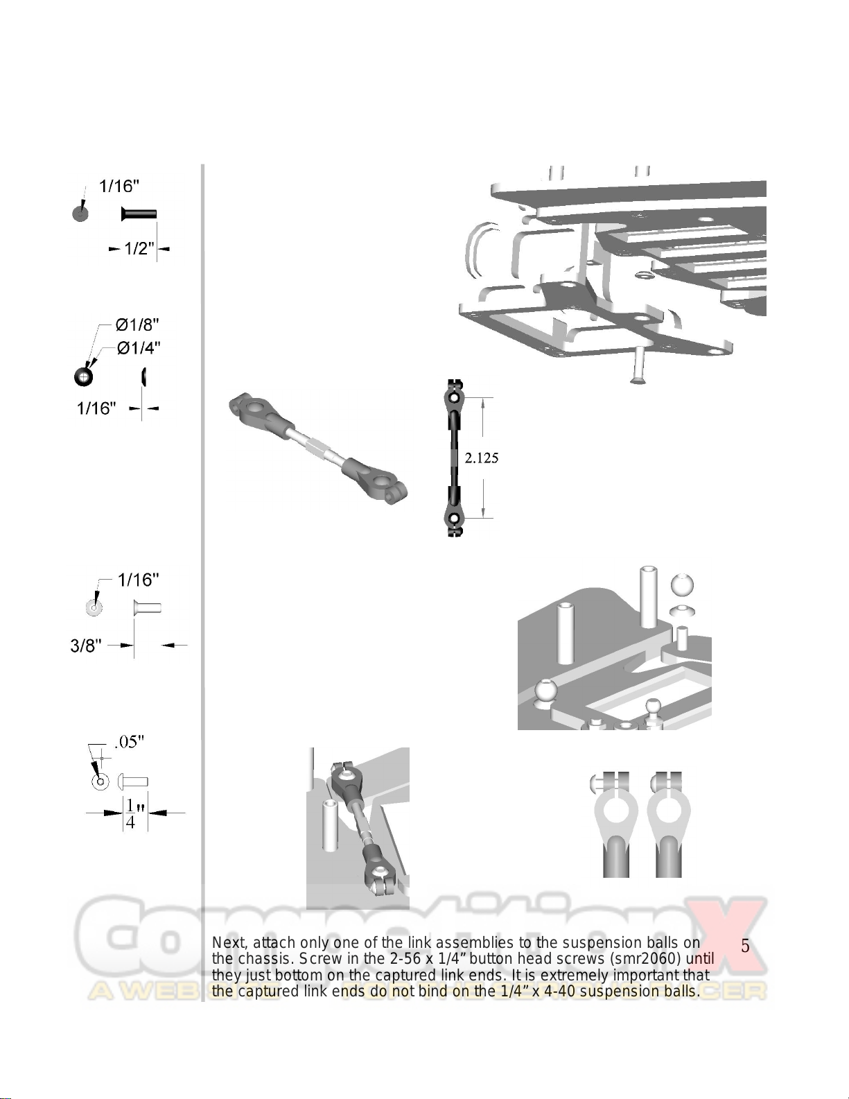
Assemble the side links from the
Link Set (smr1264), screw onto
each end of the turnbuckles one
of the captured link ends
(smr1265-s). Space the plastic
captured link ends equally 2-1/8”
apart from center to center. This
will get the link close, and will be
fine-tuned later.
Next, place two 4-40 x 3/8” flat
head screws (smr2012) through
the chassis and lower pod plate.
From the top of the chassis, place
one low roll center cone
(smr5008) on each of the screws,
followed finally by a 1/4” x 4-40
suspension ball screwed down
tightly using a small amount of
blue thread lock.
Next, attach only one of the link assemblies to the suspension balls on
the chassis. Screw in the 2-56 x 1/4” button head screws (smr2060) until
they just bottom on the captured link ends. It is extremely important that
the captured link ends do not bind on the 1/4” x 4-40 suspension balls.
4-40 x 1/2”
flat head
Low roll
center cone
4-40 x 3/8”
flat head
2-56 x 1/4”
button head
6
Holding the chassis and lower
pod plate level, examine the
gap between the main chassis
and the lower pod plate from
the bottom. The gap should be
even all the way across. Make
adjustments to the single
attached link until the gap is
even.
Next, place two 4-40 x 3/8” flat
head screws through the
chassis and lower pod plate on
the opposite side. From the
top of the chassis, place one
low roll center cone on each of
the screws, followed finally by
a 4-40 threaded ball screwed
down tight. Next attach the
second link to the opposite
side using the same method
as before.
Articulate the rear pod, twisting it left and right, noting the feeling of the
motion. The method for fine adjustment for the different actions are as
follows:
- If the motion on one side feels 'clicky', then the link on that side of the
pod is too long.
- If the motion on one side of the pod feels 'tight', then that side link is too
short.
The twisting motion from side to side of the rear pod is really important to
get correct. If not adjusted correctly, it will lead to an ill-handling car.
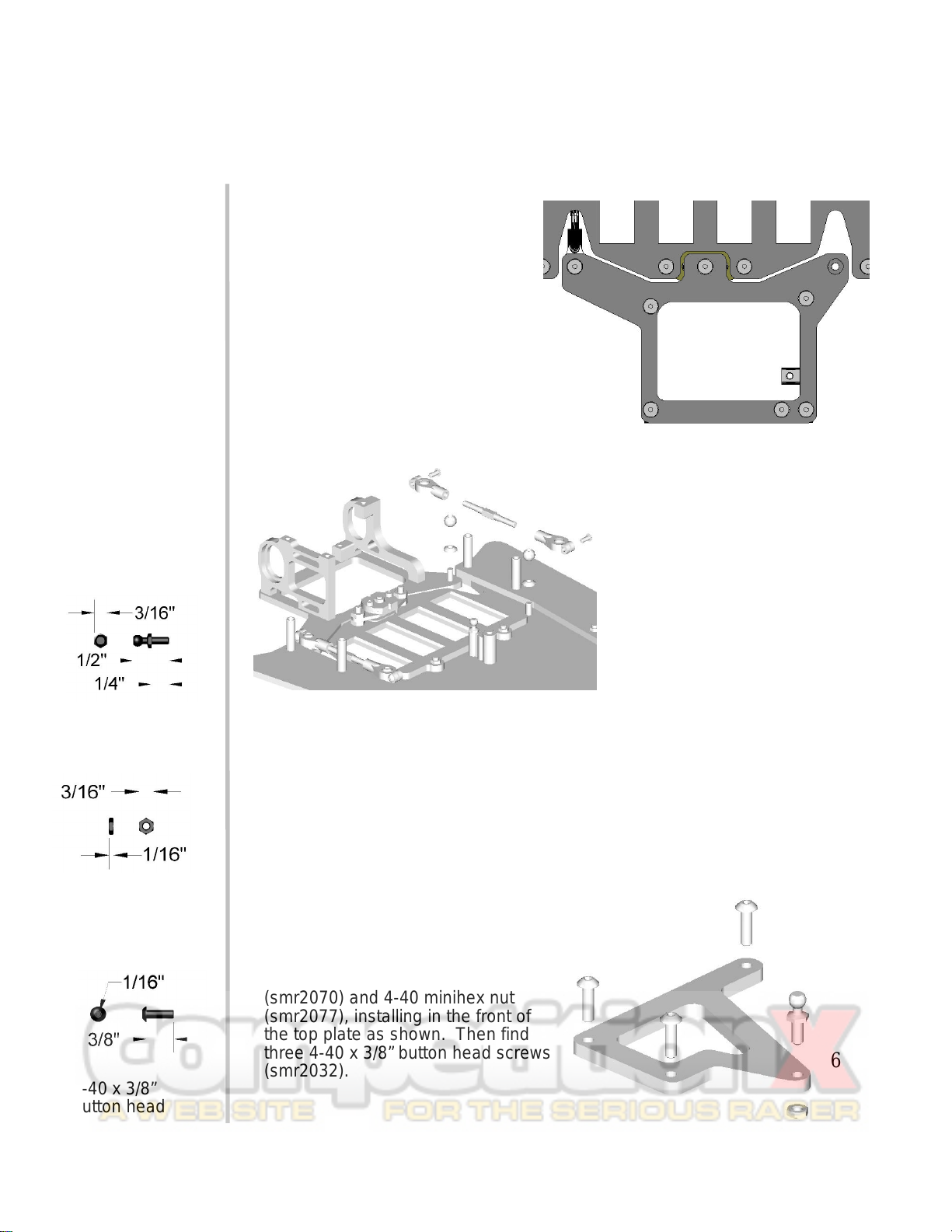
Locate a 4-40 aluminum ball stud
(smr2070) and 4-40 minihex nut
(smr2077), installing in the front of
the top plate as shown. Then find
three 4-40 x 3/8” button head screws
(smr2032).
Aluminum
ball stud
4-40 hex nut
small
4-40 x 3/8”
button head
7
Attach the upper pod plate to the
bulkheads already attached to the
lower pod, do not use thread lock
on these screws. To install a
motor (not included) into the rear
pod, the top plate will need to be
removed, and the motor installed
with the pinion shaft side first,
pivoting the rear of the motor into
place.
Locate two No. 4 axle ride height
adjusters (smr1293), and two 3/8” x
1/4” bearings (smr5001) and install
them into the rear pod. Orientate
the axle ride height adjuster so that
the bearing in the low position.
Tip: Sometimes the axle ride height
adjusters have flashing around the
edges that will need to be trimmed.
This is left on from the molding
process, and can ensure that a good fit
is possible. Trim the gate off with a
hobby knife and test fit in the milled
opening. Only sand enough material off
till the parts just slide in.
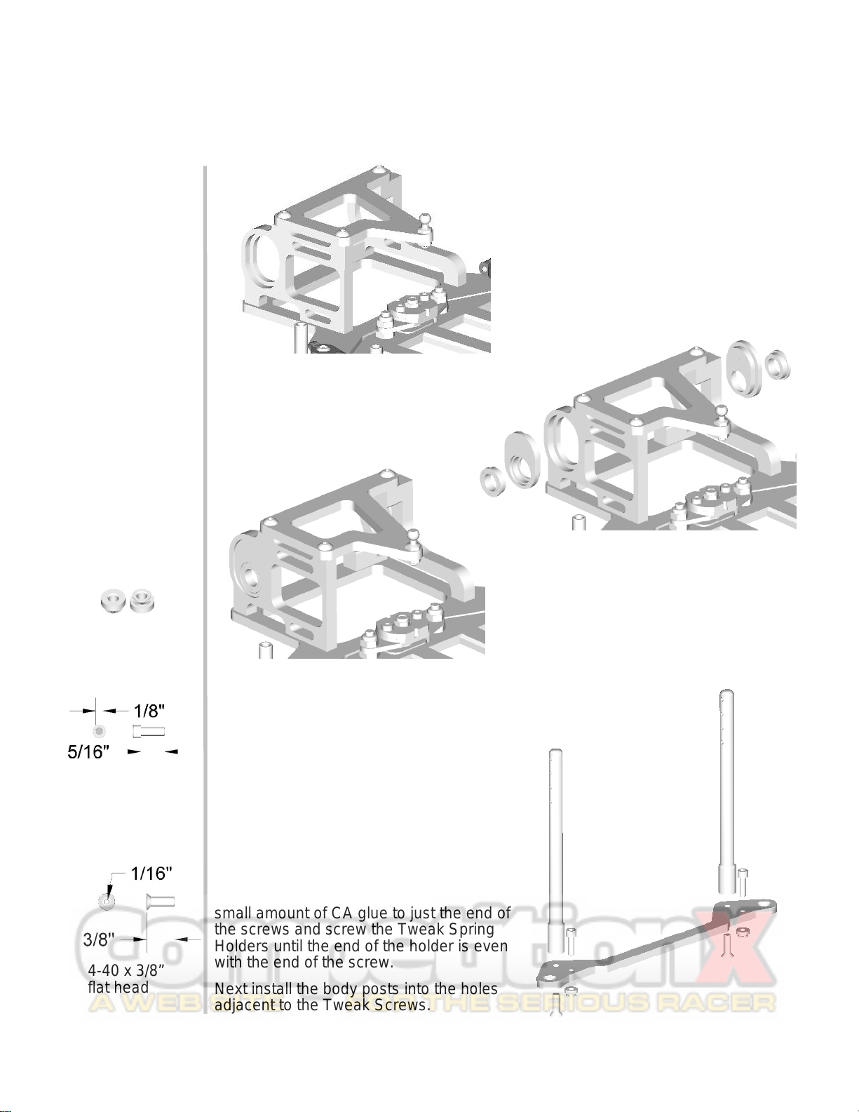
Locate the following items:
Body posts (smr1551)(x2), 4-40 x 3/8” flat
head screws (smr2012)(x2). The Tweak
spring carriers (smr1279): 4-40 x 3/8”
socket head cap screws (x2), and Tweak
Spring Holders (x2). Also the Tweak
Springs (x2) (smr5062). And the Tweak
Plate.
The top side of the Tweak Plate has the
counter sunk holes on the outside edges
facing up. Install the socket head cap
screws from the top side, threading into
the non-countersunk holes. Next, apply a
small amount of CA glue to just the end of
the screws and screw the Tweak Spring
Holders until the end of the holder is even
with the end of the screw.
Next install the body posts into the holes
adjacent to the Tweak Screws.
4-40 x 3/8”
flat head
4-40 x 3/8”
socket head
Tweak spring
holder
(top/bottom)

Install the tweak springs, only after the CA glue has
fully cured, by pushing and twisting the spring in a
clock-wise motion until it ‘clicks’ into position.
Assemble the tweak plate to the
chassis using 4-40 x 3/8” flat head
screws (smr2012)(x2) and a little
drop of blue thread lock.
Next locate the battery hold down
plate and install with 4-40 x 3/8”
flat head screws (smr2012)(x2).
Note: no thread lock here!
Find the parts bag containing the rear axle and differential (diff) parts.
From left to right shown above is; the rear axle, diff ring, 3/8” x ¼” un-flanged
bearing, 100 tooth spur gear, 1/8” diff balls (x12), diff ring, 3/8” x ¼” flanged
bearing, right hub, 3/8” x ¼” flanged bearing, thrust cone, nylon diff nut.
These components will be installed in that order. Silicone diff grease should be
used on the balls after installation into the spur gear (both sides).
Tip: to aid in the assembly, put 3 to 4 dots of grease on the axle flange, and on
the right hub before mounting the diff rings. This will hold the rings in place until
the assembly is completed.
When tightening the diff nut, tighten it down slowly until it just starts to tighten the
diff. From this point on, only tighten ¼ turn increments, spinning the axle while
holding the spur from turning. This will allow the diff to break in slowly. Keep
tightening the diff nut until it’s difficult to spin the spur while holding the axle and
right hub firmly.
4-40 x 3/8”
flat head
9
After assembling and breaking in
the differential, install the axle into
the rear pod through the right side
bulkhead. Slide all the way
through until the hub on the diff
flange is touching the bearing.
Install 4-40 x 3/8” socket head cap
screws (x2) into the left rear axle
hub, and do not tighten.
Slide three ¼” axle shims
(smr2090), and the stepped
spacer onto the axle to the
bearing, followed by the left hub
assembly completed in the step
above. Leave a hair gap between
the axle spacer and then tighten
the two socket head cap screws
located on the left hub.
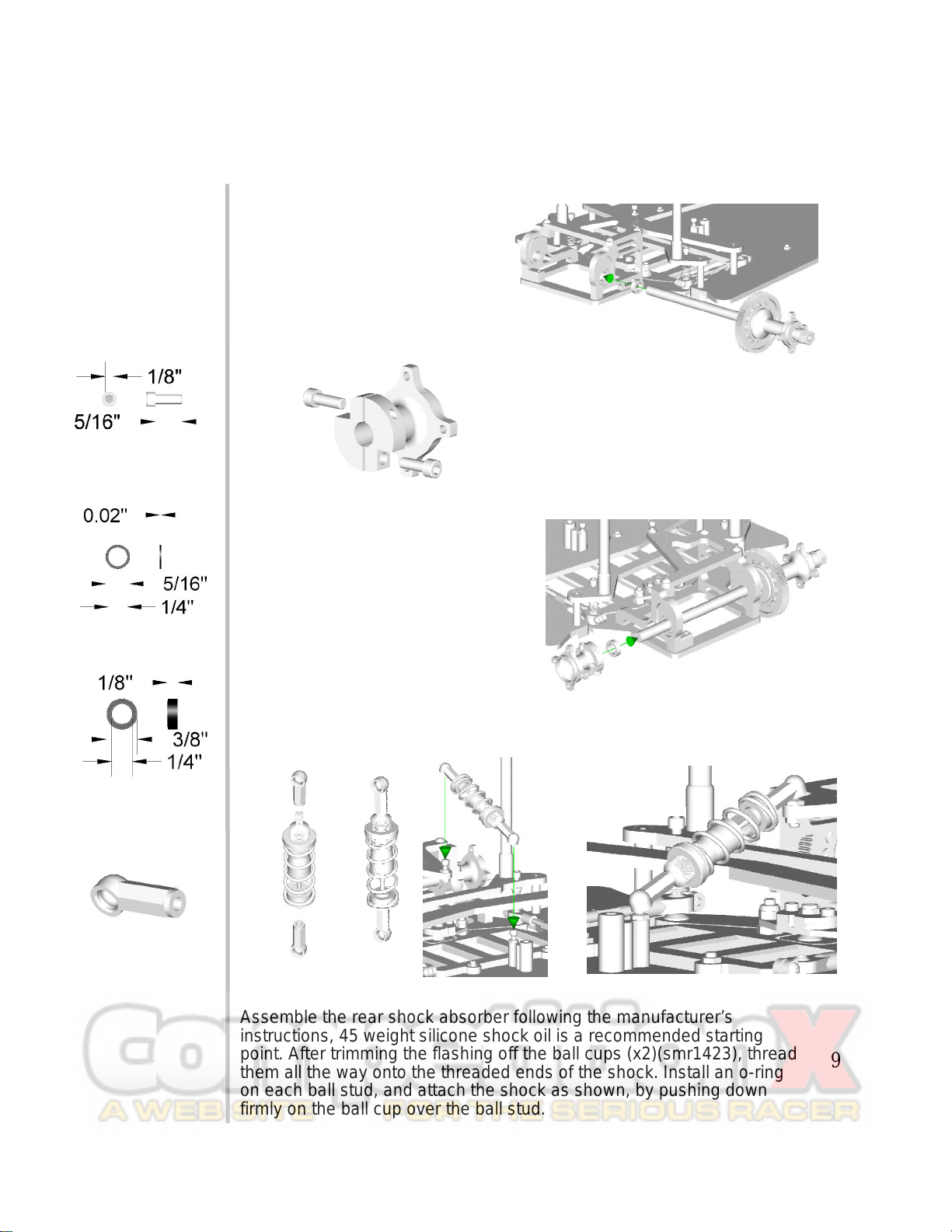
Assemble the rear shock absorber following the manufacturer’s
instructions, 45 weight silicone shock oil is a recommended starting
point. After trimming the flashing off the ball cups (x2)(smr1423), thread
them all the way onto the threaded ends of the shock. Install an o-ring
on each ball stud, and attach the shock as shown, by pushing down
firmly on the ball cup over the ball stud.
4-40 x 3/8”
socket head
1/4” axle shim
1/4” stepped
axle shim
Ball cup

10
Find the steering knuckles (smr1281)(x2), front
axles (smr1289)(x2) and E-clips (smr2092)(x2).
Install an E-clip into the groove on the axle, then
press fit the axle into the steering block threaded
end first. Press the axle all the way through the
steering block till the E-clip bottoms on the steering
block. Using a 3/32” drill, open the indicated hole on
the tabs of both steering blocks. Thread in the short
neck ball studs (smr2069), secured by 4-40 mini-
hex nuts (smr2076), use thread lock on the stud.
Noting the bump on the front of the suspension
arm (smr1289)(x2), install the steering knuckle
with the ball stud located toward the rear.
Start by installing the kingpin (smr1282)(x2)
through the top of the suspension arm, just
enough to slide the .022” spring (smr1286)
onto. Next position the steering knuckle as
mentioned above. Slide the kingpin down
carefully, taking care not to catch the spring in
the E-clip grooves.
Tip: Polish the kingpins before installing using
some metal polish for smooth operation.
When installing E-clips (smr2092),
ensure the groove in the kingpin is
aligned with the top of the steering
knuckle. Slide the first E-clip between the
knuckle and spring, firmly snapping it
into the groove.
With the top E-clip installed, installing the
bottom E-clip is as simple as sliding it
between the steering block and lower
part of the suspension arm with the clip
started on the groove. Now, let the
suspension relax. Holding the knuckle in
place, use the back side of a hobby knife
blade to snap the E-clip into place.
Drill 3/32”
hole
Note: it is recommended to wear safety glasses when installing E-clips.
E-clip
Axle
Short Neck
Ballstud
Nut
Kingpin
Front Spring
11
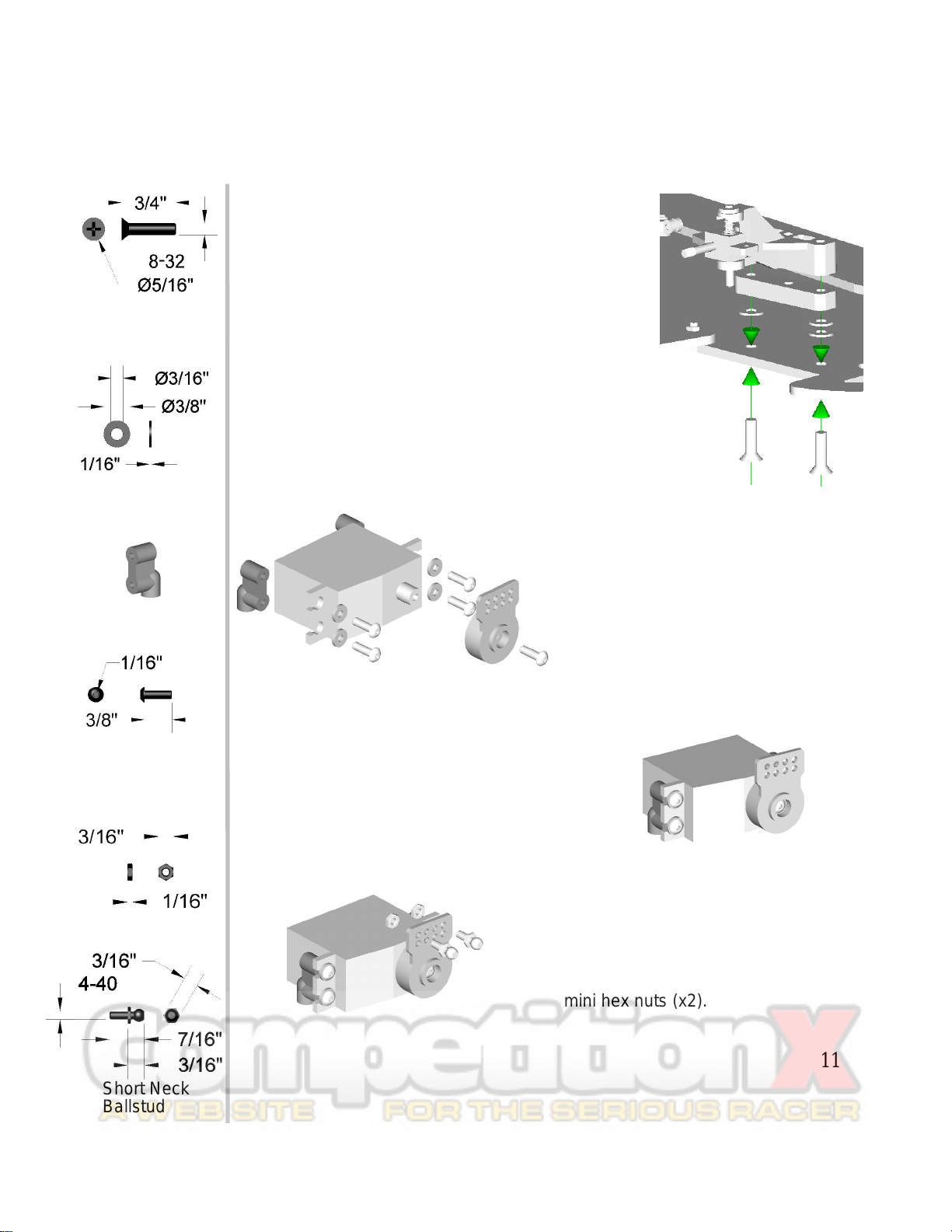
With two 8-32 x 3/4” flat-head cross-point
(phillips-head) stainless steel screws (smr2045),
mount one ride height/caster shim (smr2089)
toward the rear-most hole, and two ride
height/caster shim on the screw in the front. Pass
these screws through the plastic suspension arm
spacer, and firmly screw down the front
suspension arm.
Tip: the bump on the suspension arm faces the
front of the chassis.
Repeat the process for the opposite side.
To install your steering servo (not
included), find the servo mounts
(smr1430)(x2), 4-40 x 3/8” button
head screws (smr2032)(x4), #4
flat washers (smr2088)(x4), and a
servo saver that matches your
servo (not included). Make sure to
retain the screw that came on the
splined output shaft of the servo
to attach the servo saver.
8-32 Flat
Head Screw
Caster/ride
height shim
Servo mount
With the servo orientated in the direction
shown, assemble by passing the 4-40
button head screws through the #4
washers, screwing firmly into the servo
mounts through the mounting ears on
the servo case. Be sure to not over
tighten these screws. The bottom of the
servo mounts should be even with the
bottom side of the servo.
Install two short neck ball studs
(black) in the upper-outer most holes
on the servo saver. After putting a
drop of thread locker on the threaded
end of the ball stud, thread on 4-40
mini hex nuts (x2).
4-40 x 3/8”
button head
Nut
Short Neck
Ballstud

12
Because every servo is slightly
different in size, drilling mounting holes
for the servo is left to the builder. To
locate the holes to mount the servo,
place a piece of masking tape just
behind the suspension arms as shown.
Locate the center of the chassis on the
tape, and draw a line from front to back
as shown.
Place the servo assembly on the
chassis. Use the line drawn to
center the servo saver on the
chassis, as far forward as possible.
Be sure to have the servo as
square to the chassis as possible,
too. Locate on the tape, the holes
to mount the servo.
The line drawn across the chassis
should be the same line for both holes,
as the servo should be mounted
square to the chassis.
Drill two 1/8” holes, and countersink
the holes from the bottom side of the
chassis with an 82°countersink until the
4-40 x 3/8” flat head screws (x2) sit
flush with the bottom of the chassis.
Tip: pilot drill the holes slowly with a smaller drill bit to help locate the holes
more precisely, this will keep the larger drill bit from 'walking' away from the
intended location.
After removing the tape, use the
countersink tool to slightly chamfer the
top sides of the newly located holes. This
will remove any burrs and give the holes
a finished look. Install the servo
assembly with 4-40 x 3/8” flat head
screws (smr2012)(x2). Be sure not to
over-tighten them.
4-40 x 3/8”
flat head

13
Using the remaining plastic ball cups (x2)(smr1423) and 4-40 turnbuckles
(x2)(smr1297), assemble them into the steering linkage as shown below,
paying attention to keeping the turnbuckle equally threaded into the ball cups.
This will allow adjustment without the danger of bottoming the turnbuckle
inside the ball cup. The dimension shown is to get the length roughly the
correct length. Shown is the left hand turnbuckle, the right hand will have the
ball cup on the right facing away from you. Fine tuning of the linkage will have
to be completed when it is assembled on the model.
After installing the linkage onto the chassis, it should appear as shown below.
The remaining hardware is for mounting the front wheels: 1/8” x 5/16” flanged
bearings (x4)(smr5003) to be mounted into the front tires of your choice, 4-40
mini lock-nuts (x2)(smr2080) used to secure the front wheels to the front axles.
Tip: be sure when tightening the front wheel nuts not to crush the bearings.
The nuts should just touch the inner bearing race with the wheel seated flush
against the steering block. To test for over tightened nuts, spin the wheel while
tightening the wheel nut. When the nut causes the wheel to slow, back the nut
off until there isn't any more compression and the wheel spins freely.
More remaining hardware is as follows: 4-40x 1/2” socket head cap
screws (x8)(smr2024). These are used for mounting the rear tires of your
choice. Tighten these till the screws are firmly secured. Over tightening
will cause the rims to deform and not run true. It could also lead to
premature rim failure.
Installing the electronics using the layout shown has proven to be the
most efficient layout. This allows the positive wires to go to the battery on
the left side, then straight back to the motor (non-reversing ESC). The
negative battery lead to the right, while the motor negative goes straight
back. Tip: route the motor wires down the centerline of the car, following
the shock. This will keep from imposing tweak between the motor pod
and main chassis.
Other Speed Merchant Motorized Toy Car manuals


