Speed Merchant Formula World GT 200 User manual

f200.0.0d
WWW.TEAMSPEEDMERCHANT.COM
Formula World GT 200
DRAFT COPY

Congratulations on your purchase of a Speed Merchant Formula
World GT 200 competition chassis.
This instruction manual will detail the specific steps involved to
uild your new chassis. Make sure to take your time when
uilding, since even though there are very few parts involved in
uilding a Formula World GT 200, it is very important to make
sure that all parts operate smooth and free. Some parts included
have a protective coating that should e removed and polished
(sliding and pivoting parts). Attention to small details like this will
make the difference etween a chassis that wins national
championships, and one that doesn't handle at all.
Required tools and supplies:
.050” Hex driver
1/16” Hex driver
3/32” Hex driver
5/64” Hex driver
3/16” Nut driver
1/4” Nut driver
3/32” Nut driver
File (wide, fine toothed)
Super Glue a.k.a. CA
35 wt. Shock Oil
Tu e Spooge (damper tu e fluid)
1/8” and 3/32” Drill its
82° countersink
Fine grit sandpapers
Metal polish
Dou le sided tape (servo tape)
Ruler
Pen or pencil
Additional parts required to
finish this chassis:
540 sized electric motor
Electronic Speed Controller
Radio Transmitter
Radio Receiver
Servo (mini sized)
Servo saver
(small sized, and to
match servo rand)
4 Cell Su -C size
NiMh Nickel Metal
Hydride Battery
Tires and Wheels
Body shell
Paint to finish ody shell
Introduction, Supplies and Additional Equipment
2Formula World GT 200
Warning: The car on fi er plates that make up
the components of this chassis do conduct
electricity, and care must e taken to ensure
that the atteries do not short on the chassis.
Carefully, using a fine toothed file, just reak
over the edge of the attery slots at a 45°
angle. The goal is to keep the chassis from
cutting the la els on the atteries during regular
use. The attery slots have een optimized for
newer cells and do not need to have a large
amount of material removed. It is est to have a
freshly assem led attery pack near y to check
the slots for proper depth. Only remove enough
material so that the attery pack will sit flush
with the ottom of the chassis, no lower.
Tip: If you filed the slots too low, they can e
carefully uilt ack up to proper height y
coating the edges with super glue.
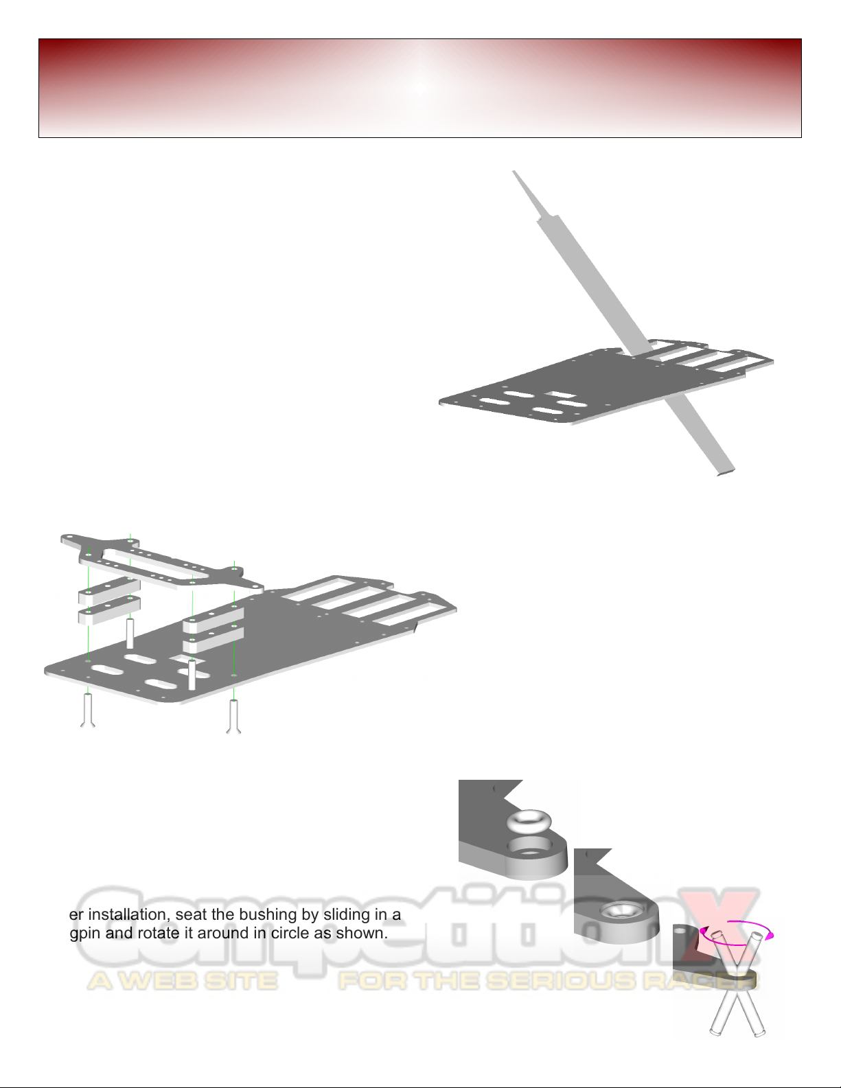
Using the provided stainless steel 8-32 x
3/4” cross point (phillips) screws (x4), attach
the lower front suspension arm ( e sure the
pockets for the pivots are facing down. The
screws will thread into the holes shown. Be
sure to keep the plate as even as possi le,
tightening opposite screws a little at a time
equally. This will ensure that attaching these
two plates together will not introduce any
tweak into the chassis. Do not over tighten.
Note: to adjust ride height, use the included
aluminum washers, equally, etween plastic
spacers and chassis plate.
Next, install the Teflon ushings (x2) into the
pockets in the ottom of the front suspension arm
as shown. This will e a tight fit and may require
significant pressure from the ack end of a smooth
screw driver to press them in. Be sure to support
the top of the arm plate while installing.
After installation, seat the ushing y sliding in a
kingpin and rotate it around in circle as shown.
Chassis Finishing and Front Suspension 3
Formula World GT 200

Install the axles y threading them into the knuckles as
shown. The thread that is on the axles is a left-hand thread.
After the hex on the axle ottoms on the plastic knuckle, then
install 4-40 nut as shown.
Install the lue aluminum all studs as shown. Do not over
tighten.
There are 8 captured all links with rass alls. 4 of the alls in
the links have een ored out to slide over the kingpins. Locate
a king pin and separate out the 4 ored captured all links.
Now locate the 4-40 x 1 3/8” turn uckles (x4). Assem le a
captured all link onto each end of the turn uckle, eing sure
that there is one ored out captured all link and one non- ored
out captured all link on each turn uckle.
Starting point on this chassis will e 4° caster and -2° cam er. To
make the settings easier to o tain, using calipers, set the front
links at 2.455” [62.36 mm] center of the all to center of the
other all, and the rear links at 2.244” [56.99 mm] from center to
center.
Tip: install the all links onto the turn uckles so that the
adjustment directions are in the same direction for each link. I.E.,
two of the ored out captured all links should e on a left-hand
thread, and two should e on a right-hand thread. When
installing these on the front of the car, e sure that the left-
threaded, ored captured all links are on the same sides of the
chassis. This way, the same direction the wrench is turned on all
links causes the turn uckles to screw in or out is the same for all
the links.
Tip: carefully remove the alls from the plastic end and polish
the all with some polishing compound for smooth operation.
Front Suspension Components Assem ly
4Formula World GT 200
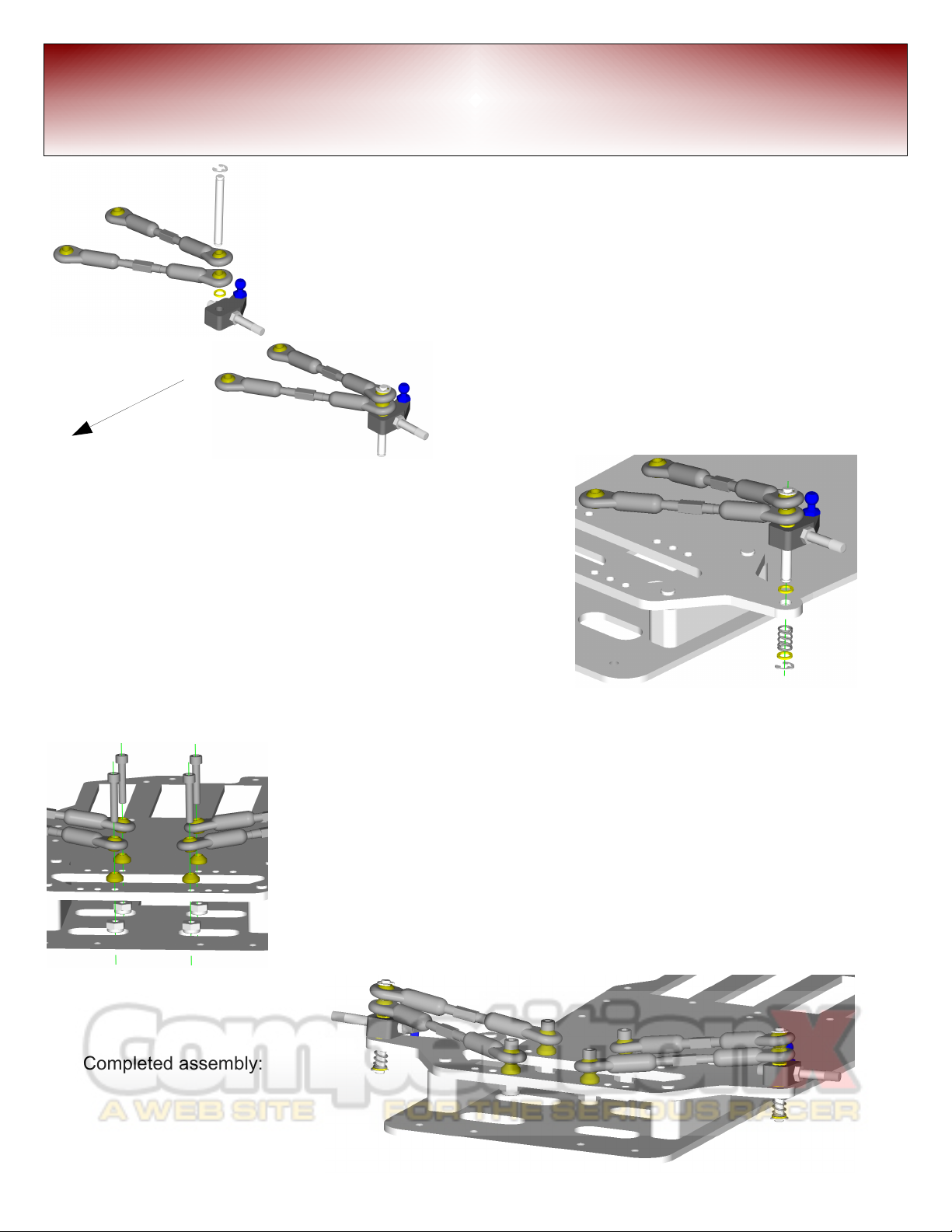
Locating the kingpins (x2), and the previously
assem led front links and steering locks, along with
1/8” E-clips, assem le as follows; Install the kingpin
into the steering lock to a out the middle of the
kingpin. Next, install one .022” rass shim, then slide
on the longer link (front) first followed y the shorter
link (rear). Install the E-clip onto the top of the the king
pin. Now slide the links and steering lock to the top
of the kingpin, taking up the slack at the top of the
kingpin.
To install the strut assem ly into the chassis, start y
locating the .022” rass shims (x2), .020” springs (x2) and
another E-clip. Slide a shim onto the ottom of the
kingpin, then slide the kingpin through the lower arm and
through the previously installed teflon ushings. Next
follow this y installing another .022” shim, the spring,
another shim followed y an E-clip.
Using the 4-40 x 5/8” socket head cap screws (x4), rass cone washers
(x4) and large 4-40 lock-nuts (x4), attach the links to the lower arm. Slide
the screws through the captured all ends, through the cone washers,
then thread them into the holes closest to the center of the chassis.
Keeping a hex driver in the screw, use a nut driver to install the 4-40 nuts
from elow the chassis. The screws should e held snug to the car on
lower arm when tightening the nuts.
Tip: do not clearance drill the car on plate. These screws are meant to e
threaded into the car on. This will keep the suspension accurate.
Completed assem ly:
Front Suspension Components Assem ly 5
front
Formula World GT 200
You will need a medium sized servo saver to match the servo you chose for your
car. We recommend standard size servos designed for 10th scale chassis. Low
profile servos aren't required for your Formula World GT 200.
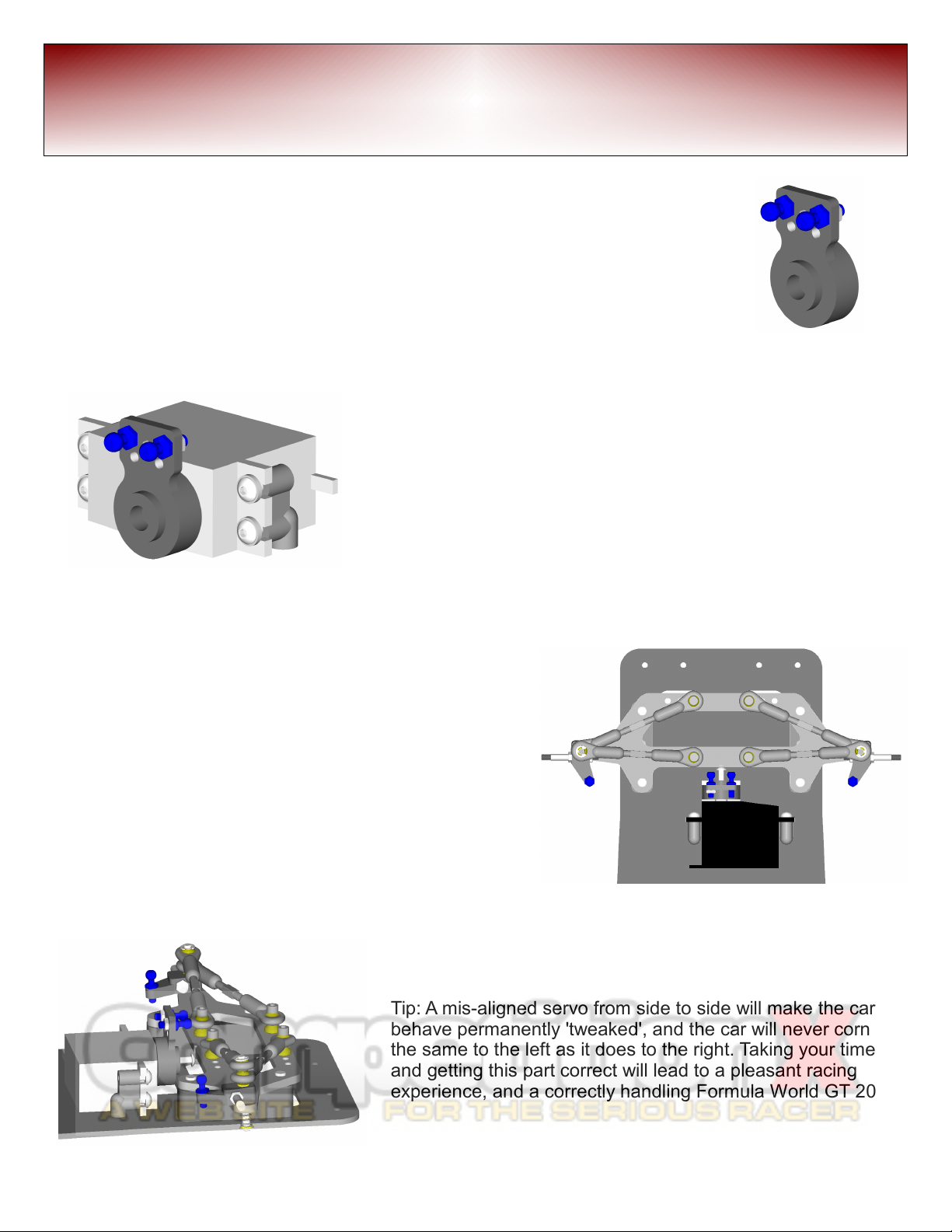
Locate the aluminum all studs (x2) ( lue anodized) and the mini (flat) 4-40 hex
nuts (x2). Install the all studs in the locations indicated.
Using the kit supplied servo mounts, attach them to the servo
using the provided 4-40 x .375 utton head screws (x4). This
illustration shows the use of washers under the screws to help
distri ute the stresses of racing.
To center the servo saver within the travel of the servo, first, turn
on your transmitter and center the trims and su -trims according
to your transmitter's instructions. Next, attach the servo to your
receiver and power it up either with a receiver pack, or using the
attery and electronic speed controller that you will e using in
this car. When the servo responds and centers up, attach the
servo saver as straight as possi le. Don't worry a out it eing
slightly off center, this can e trimmed in on track.
Installing a long utton head screw into the mounting hole of the
servo saver will allow alignment with the alignment notch in the
lower arm. Once the servo is squared onto the arm, mark the
hole locations for the servo mounts from side to side.
Pull the utton head screw out, and align the servo saver with
the slot in the chassis and mark the position on the chassis for
the front to rear placement of the servo for mounting holes in the
chassis.
After carefully marking the center of the servo mounting
holes, place the assem led servo ack on the chassis to
make sure the marked holes appear where they should e.
Tip: A mis-aligned servo from side to side will make the car
ehave permanently 'tweaked', and the car will never corner
the same to the left as it does to the right. Taking your time
and getting this part correct will lead to a pleasant racing
experience, and a correctly handling Formula World GT 200.
Next, remove the servo and drill the holes and countersink
(82°) them from the ottom so that the screw heads are
flush.
Steering Servo Installation
6Formula World GT 200
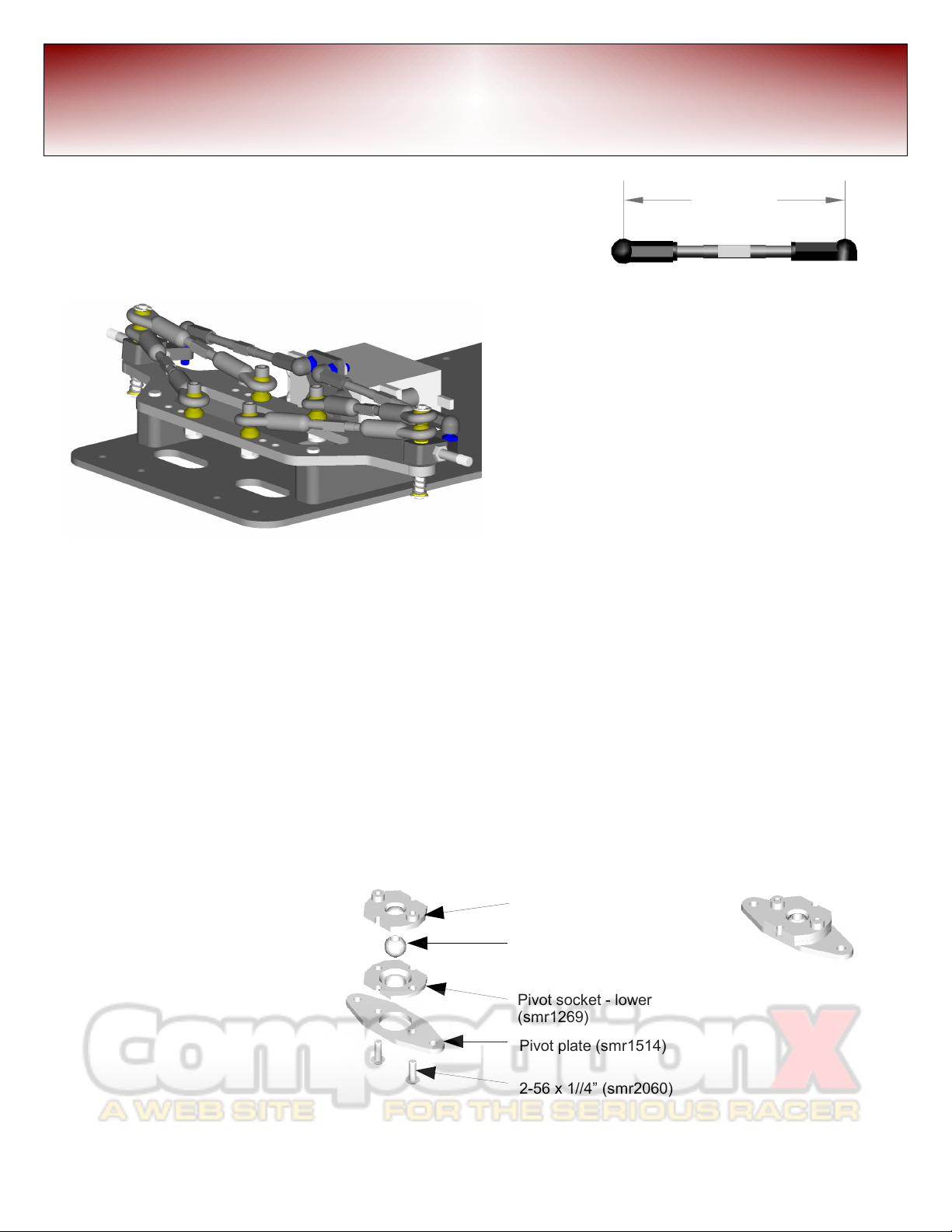
2.385Locate the allcups and 4-40 x 1 3/8” turn uckles (x2).
Assem le one as shown and the other opposite hand, to the
length shown (2.385”), measuring with a caliper from center
to center. This num er should get the links close, and can e
fine-tuned later for proper toe-in / out.
This completes the Speed Merchant World GT
Formula front suspension assem ly.
Tip: adjusting the cam er and caster can also e adjusted with the aid of a spare roll-over antenna
inserted in place of the kingpins, using a cam er gage. Always adjust for cam er first then the caster
angle.
To raise or lower the front ride height to run smaller or larger diameter tires, spacers can e added or
removed equally etween the plastic spacers and the chassis. Included in the kit are aluminum
spacer washers that are meant specifically for that purpose. These spacers are availa le in oth .
030” and .060”. Note, to run really low profile tires, you may need to remove a plastic spacer from
each side.
Rear Suspension
Assem le the center pivot plate
with the pivot socket set
(smr1268), in the configuration
shown, fastening with 2-56 x 1/4”
utton head screws (x2).
Pivot plate (smr1514)
2-56 x 1//4” (smr2060)
Suspension all
Pivot socket - lower
(smr1269)
Pivot socket - upper
(smr1269)
completed pivot
Steering Assem ly – Rear Suspension Assem ly 7
Formula World GT 200
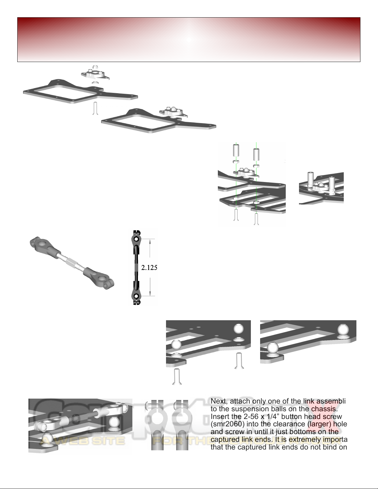
Attach rear pod plate to the center pivot
using a 4-40 x 1/2” flat head screw
(smr2014). Use a low roll center cone
(SMR5008) on top of the lower pod
plate, screwing through the 1/4” x 4-40
threaded suspension all in the center
pivot. Secure using a 4-40 mini-locknut
(SMR2080) as a jam nut.
Before
After
Attach the lower pod plate/pivot assem ly to the main
chassis using 4-40 x 1/2” flat head screws (x2)
(smr2014) with 4-40 hex nuts (x2) (smr2078). Slide
center pivot assem ly onto the 4-40 screws and
secure with 4-40 hex nuts (x2) (smr2078) followed y
the tweak plate stand-offs (x2)(smrxxxx).
Before After
Assem le the side links from the Link Set
(smr1264), screw onto each end of the
turn uckles one of the captured link ends
(smr1265-s). Space the plastic captured link ends
equally 2-1/8” apart from center to center. This will
get the link close, and will e fine-tuned later.
Next, place two 4-40 x 3/8” flat head
screws (smr2012) through the chassis
and lower pod plate. From the top of the
chassis, place one low roll center cone
(smr5008) on each of the screws,
followed finally y a 1/4” x 4-40
suspension all screwed down tightly
using a small amount of lue thread lock.
Next, attach only one of the link assem lies
to the suspension alls on the chassis.
Insert the 2-56 x 1/4” utton head screw
(smr2060) into the clearance (larger) hole,
and screw in until it just ottoms on the
captured link ends. It is extremely important
that the captured link ends do not ind on
the 1/4” x 4-40 suspension alls.
Rear Suspension Assem ly
8Formula World GT 200
Holding the chassis and lower pod plate level,
examine the gap etween the main chassis and the
lower pod plate from the ottom. The gap should e
even all the way across. Make adjustments to the
single attached link until the gap is even.
Next, place two 4-40 x 3/8” flat
head screws through the
chassis and lower pod plate on
the opposite side. From the
top of the chassis, place one
low roll center cone on each of
the screws, followed finally y
a 4-40 threaded all screwed
down tight. Next attach the
second link to the opposite
side using the same method
as efore.
Articulate the rear pod plate, twisting it left and right, noting the feeling of the motion. The method for
fine adjustment for the different actions are as follows:
- If the motion on one side feels 'clicky', then the link on that side of the pod is too long.
- If the motion on one side of the pod feels 'tight', then that side link is too short.
The twisting motion from side to side of the rear pod is really important to get correct. If not adjusted
correctly, it will lead to an ill-handling car. If the plate gap was adjusted properly in the previous step,
the last link attached should e the only link in need of adjustment.
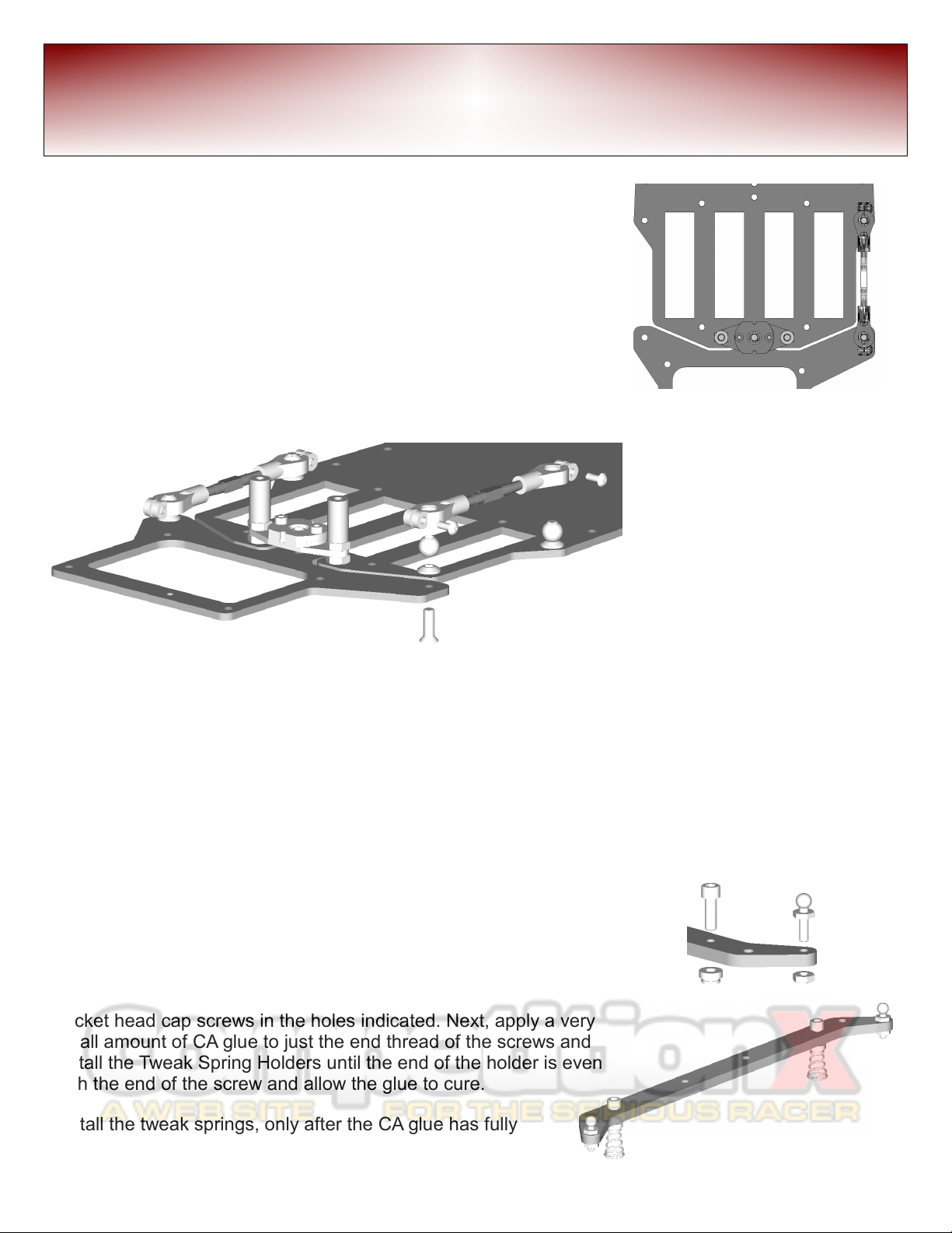
Locate the following items:
2-56 all stud (x2) and 2-56 nut, tweak spring carriers (smr1279):
4-40 x 3/8” socket head cap screws (x2), and Tweak Spring Holders
(x2) and the Tweak Plate.
Install the 2-56 all stud into the end of the tweak plate and put a
2-56 nut on the end (x2). Skipping a set of holes in, Install the
socket head cap screws in the holes indicated. Next, apply a very
small amount of CA glue to just the end thread of the screws and
install the Tweak Spring Holders until the end of the holder is even
with the end of the screw and allow the glue to cure.
Install the tweak springs, only after the CA glue has fully
cured, y pushing and twisting the spring in a clock-wise
motion until it ‘clicks’ into position.
Rear Suspension Assem ly 9
Formula World GT 200

With the tweak spring
holders adjusted all the
way up, install onto the
chassis using 4-40 x
3/8” flat head screws
(x2) through the
countersunk washers
(x2), into the stand-offs.
After locating 1 aluminum all
stud, the shock/antenna
mount, and 4-40 x 3/8” screws
(x2), install the shock mount in
the orientation as shown.
Locate the ulkhead plates for the
rear pod and 4-40 x 1/4” flathead
screws (x4), and attach to the lower
pod plate as shown, eing sure not to
over-tighten.
Next, attach the rear car on fi er pod
plate using 4-40 x 1/4” utton head
screws (x4), again eing sure not to
over-tighten.
Before attaching the upper pod plate,
attach the following all studs; lue
anodized 4-40 all stud in the center
hole, and the shorter 2-56 all studs
from the opposite side of the plate,
securing with nuts and thread lock.
Attach this assem ly, with the 2-56
all studs (x2) on the ottom side to
the rear pod with 4-40 x 1/4” utton
head screws (x4).
Rear Suspension Assem ly
10
Attach the attery
positioner as shown on
the chassis and attach
with 4-40 x 3/8” flat
head screws (x2) and
4-40 flat nuts (x2) as
shown.
Formula World GT 200

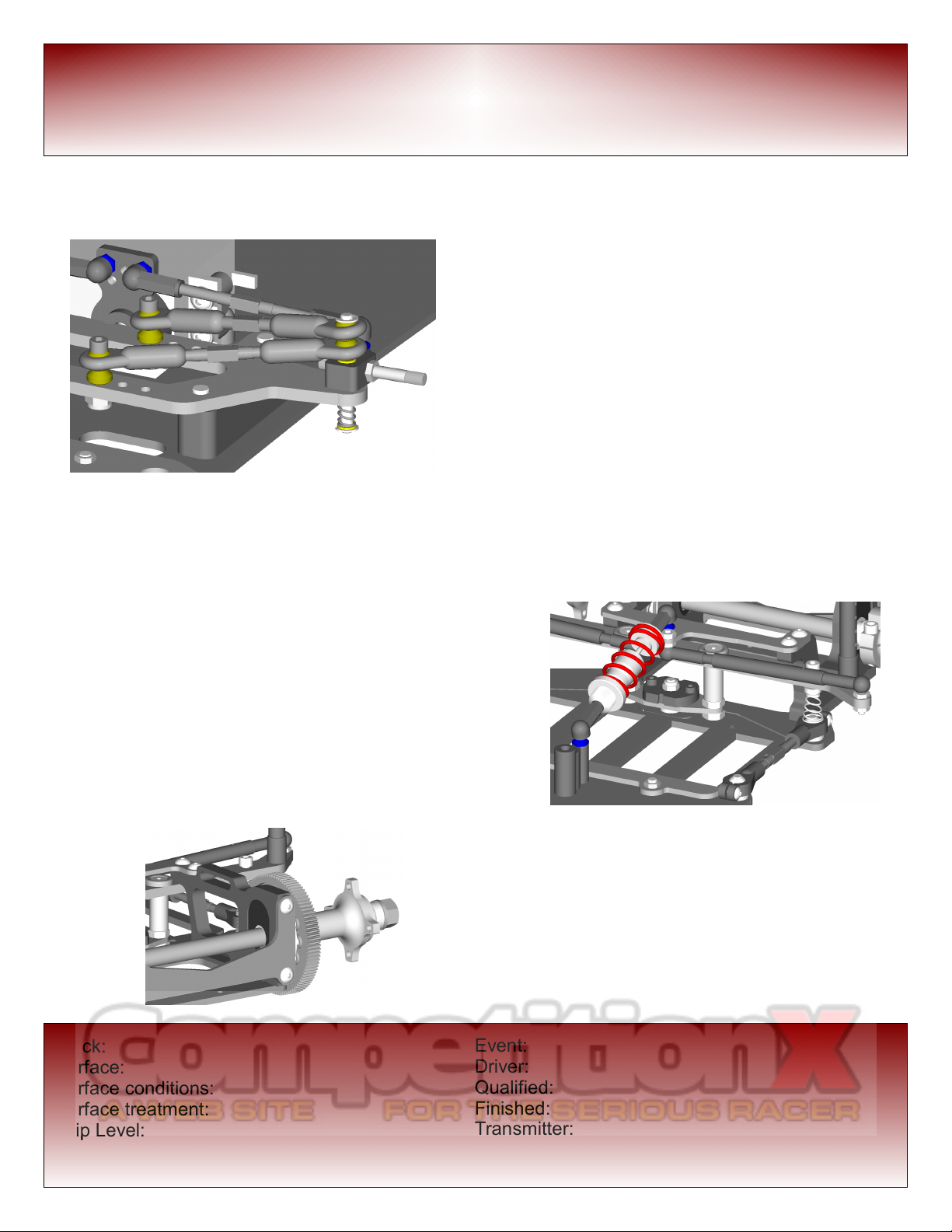
Locate the parts to assem le the side damper
tu es, including damping fluid (not included, we
recommend Tu e Spooge) of your choice. Install
the 2-56 gru screws into the all cup, and screw
the damper shafts and tu es as shown. Next, fill
the tu e with Medium Tu e Spooge until it leeds
out the reather hole. Having a rag ready, insert
the damper shaft into the tu e slowly working the
shaft ack and forth to fully coat with the Tu e
Spooge. Wipe off access Tu e Spooge, and
repeat with other damper.
Install the damper tu es in the orientation shown.
Periodically, remove the damper tu es, clean and
refill with Tu e Spooge. When constructed, the
tu es should have equal damping. If not, clean out
and re-fill oth tu es.
Assem le the shock using the included instructions that
came with the shock. We suggest using 35 weight oil
inside the shock to start with. Different temperatures and
track conditions will dictate what set-up suits your
situation est. Install all cups on each end of the shock.
Tip: Install the shock in the direction
shown, this will help keep track de ris off
the piston shaft. To remove the shock for
attery installation, use a pair of needle
nose pliers to gra the all cup attached
to the shock ody, as close to the shock
ody and rotate on the axis of the shock.
It should pop right off the all stud on the
shock/antenna mount.
Rear Suspension Assem ly 11
Formula World GT 200
Locate the rear axle ride height adjusters (No. 4) (x2) and
the 3/8” x 1/4” flanged axle earings (x2). Install the ride
height adjusters into the ulkhead plates. Install the
earings into the ride height adjusters. Tip: we suggest to
leave the flashing on these parts, only trimming the gate
material. Keeping the flashing on these parts will insure a
nice tight fit. If the compression caused y the press fit is
causing the earings to not operate properly, reaming out
the earing holes with a stepped prop reamer will usually
alleviate that compression on the earing.
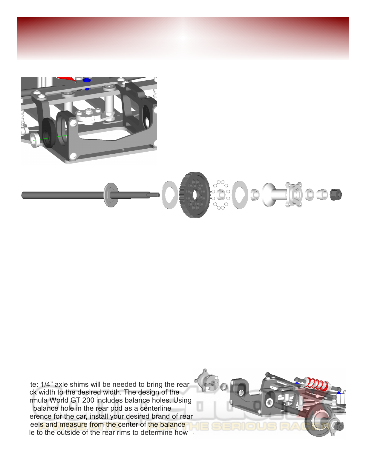
From left to right shown a ove is; the rear axle, diff ring, 100 tooth spur gear, 3/8” x ¼” un-flanged
earing, 1/8” diff alls (x12), diff ring, 3/8” x ¼” flanged earing, right hu , 3/8” x ¼” flanged earing,
thrust cone, nylon diff nut.
These components will e installed in that order. Silicone diff grease should e used on the alls after
installation into the spur gear ( oth sides).
Tip: to aid in the assem ly, put 3 to 4 dots of grease on the axle flange, and on the right hu efore
mounting the diff rings. This will hold the rings in place until the assem ly is completed.
When tightening the diff nut, tighten it down slowly until it just starts to tighten the diff. From this point
on, only tighten ¼ turn increments, spinning the axle while holding the spur from turning. This will
allow the diff to reak in slowly. Keep tightening the diff nut until it’s difficult to spin the spur while
holding the axle and right hu firmly.
Install axle into rear pod. Slide on left hu and tighten
the screws to secure the left hu , and axle assem ly.
Note: 1/4” axle shims will e needed to ring the rear
track width to the desired width. The design of the
Formula World GT 200 includes alance holes. Using
the alance hole in the rear pod as a centerline
reference for the car, install your desired rand of rear
wheels and measure from the center of the alance
hole to the outside of the rear rims to determine how
many shims are required for your desired rear track
width.
Differential Assem ly and Installation
12 Formula World GT 200

Attach the remaining two ody posts to the tweak
plate with 4-40 x 3/8”socket head cap screws (x2).
Attach the nerf plates to the main chassis just ahead
of the side links using 4-40 x 1/4” socket head cap
screws (x2) and 4-40 flat nuts (x2). Use lue thread
lock on the screws for the nerf plates.
Attach the front umper with 4-40 x ¼ flat head screws (x2) and 4-40 flat nuts, leaving loose until the
ody posts are attached use lue thread lock on the screws. Next attach the ody posts and attach
with 4-40 x 3/8” long flat head socket head cap screws (x2). Now finish tightening the screws to the
umper.
Bumper, Body Post Attachment 13
Completed chassis assem ly.
Formula World GT 200
Set-up Sheet
14
Front suspension springs:
Cam er angle:
Cam er link position:
Cam er link cone:
Cam er link shims:
Steering all stud shims:
Caster angle:
Caster link position:
Caster link cone:
Caster link shims:
Ride height locks (qty):
Ride height shims:
Front ride height (measured):
Front axle shim(s):
Front axle shim(s) position:
Tire compound / rand / rim:
Tire diameter:
Traction additive:
Quantity of tire treated:
Additional tire preparation:
Center shock:
Shock oil ( rand, weight):
Shock spring:
Shock shim height:
Damper tu e fluid:
Side springs:
Ride height:
Droop height:
Battery position:
Roll cone height:
Axle ride height adjuster:
Track width:
Rear ride height (measured):
Tire compound \ rand \ rim:
Tire diameter:
Traction additive:
Quantity of tire treated:
Additional tire preparation:
Track:
Surface:
Surface conditions:
Surface treatment:
Grip Level:
Temperature:
Weather conditions:
Event:
Driver:
Qualified:
Finished:
Transmitter:
Speed Controller:
Motor / winds / roll-out:
Formula World GT 200
Table of contents
Other Speed Merchant Motorized Toy Car manuals

Popular Motorized Toy Car manuals by other brands


Tamiya
Tamiya Mitsubishi Lancer Evolution VII WRC TB-01 manual

Radio Shack
Radio Shack 60-4436 owner's manual

Jamara Kids
Jamara Kids Offroader Bufalo instructions

Panda Hobby
Panda Hobby Tetra X1 instruction manual

Excalibur
Excalibur Water Fusion Car EI-PT1010 user manual

Traxxas
Traxxas 67014-4 Assembly manual


