Speeflo S-3 User manual
P/N 313-2440B © 2004 Titan Tool Inc. All rights reserved. 1
Owner’s Manual
For professional use only
Safety Precautions
This manual contains information that must be read and
understood before using the equipment. When you come to an
area that has one of the following symbols, pay particular
attention and make certain to heed the safeguard.
This symbol indicates a potential hazard which may cause
serious injury or loss of life. Important safety information
will follow.
This symbol indicates a potential hazard to you or to the
equipment. Important information that tells how to prevent
damage to the equipment or how to avoid causes of minor
injuries will follow.
HAZARD: Injection injury — A high pressure fluid stream
produced by this equipment can pierce the skin
and underlying tissues, leading to serious injury
and possible amputation. See a physician
immediately.
DO NOT TREAT AN INJECTION INJURY AS A SIMPLE CUT!
Injection can lead to amputation. See a physician immediately.
The maximum operating range of the gun is 3900 PSI / 27
MPa fluid pressure.
PREVENTION:
• NEVER aim the gun at any part of the body.
• NEVER allow any part of the body to touch the fluid stream.
DO NOT allow body to touch a leak in the fluid hose.
•NEVER put hand in front of the gun. Gloves will not
provide protection against an injection injury.
• ALWAYS lock the gun trigger, shut pump off, and release all
pressure before servicing, cleaning tip or guard, changing
tip, or leaving unattended. Pressure will not be released by
turning off the motor. The PRIME/SPRAY valve or pressure
bleed valve must be turned to their appropriate positions to
relieve system pressure. Refer to the PRESSURE RELIEF
PROCEDURE described in the sprayer’s Owner’s Manual.
• ALWAYS keep tip guard in place while spraying. The tip guard
provides some protection but is mainly a warning device.
• ALWAYS remove the spray tip before flushing or cleaning
the system.
• Paint hose can develop leaks from wear, kinking and
abuse. A leak can inject material into the skin. Inspect the
hose before each use.
• NEVER use a spray gun without a working trigger lock and
trigger guard in place.
• All accessories must be rated at or above the maximum
operating pressure range of the airless sprayer. This
includes spray tips, guns, extensions, and hose.
NOTE TO PHYSICIAN:
Injection into the skin is a traumatic injury. It is
important to treat the injury as soon as possible. DO
NOT delay treatment to research toxicity. Toxicity is a
concern with some coatings injected directly into the
blood stream. Consultation with a plastic surgeon or
reconstructive hand surgeon may be advisable.
WARNING
NOTE: Notes give important information which should
be given special attention.
CAUTION
WARNING
HAZARD: EXPLOSION AND FIRE - Solvent and paint fumes
can explode or ignite. Severe injury and/or
property damage can occur.
PREVENTION:
• Provide extensive exhaust and fresh air introduction to keep
the air within the spray area free from accumulation of
flammable vapors.
• Avoid all ignition sources such as static electricity sparks,
electrical appliances, flames, pilot lights, hot objects, and
sparks from connecting and disconnecting power cords or
working light switches.
• Do not smoke in spray area.
• Fire extinguisher must be present and in good working order.
• Place pump at least 25 feet (7.6 m) from the spray object in
a well ventilated area (add more hose if necessary).
Flammable vapors are often heavier than air. Floor area
must be extremely well ventilated. The pump contains
arcing parts that emit sparks and can ignite vapors.
• The equipment and objects in and around the spray area
must be properly grounded to prevent static sparks.
• Use only conductive or grounded high-pressure fluid hose.
Gun must be grounded through hose connections.
• Power cord must be connected to a grounded circuit.
• Always flush unit into separate metal container, at low pump
pressure, with spray tip removed. Hold gun firmly against
side of container to ground container and prevent static
sparks.
• Follow material and solvent manufacturer's warnings and
instructions.
• Use extreme caution when using materials with a flashpoint
below 70° F (21° C). Flashpoint is the temperature at which
a fluid can produce enough vapors to ignite.
• Plastic can cause static sparks. Never hang plastic to
enclose spray area. Do not use plastic drop cloths when
spraying flammable materials.
• Use lowest possible pressure to flush equipment.
GAS ENGINE (WHERE APPLICABLE)
Always place pump outside of structure in fresh air. Keep all
solvents away from engine exhaust. Never fill fuel tank with a
running or hot engine. Hot surface can ignite spilled fuel.
Always attach ground wire from pump to a grounded object.
Refer to engine owner’s manual for complete safety information.
HAZARD: EXPLOSION HAZARD DUE TO INCOMPATIBLE
MATERIALS - Will cause severe injury or property
damage. Some pumps and accessories contain
aluminum and cannot be used with halogenated
hydrocarbon solvents. Follow the prevention
section if your pump or accessories are not
compatible with halogenated hydrocarbon
solvents. The S-3 Airless Spray Gun is
compatible with halogenated hydrocarbon
solvents.
PREVENTION:
• Do not use materials containing bleach or chlorine.
• Do not use halogenated hydrocarbon solvents such as
bleach, mildewcide, methylene chloride and 1,1,1 -
trichloroethane. They are not compatible with aluminum.
• Contact your coating supplier about the compatibility of
material with aluminum.
S-3
Airless Spray Gun Model Number 550-250
3900 PSI Maximum Operating Pressure/Stainless Steel Fluid Passages

2 P/N 313-2440B © 2004 © Titan Tool Inc. All rights reserved.
HAZARD: HAZARDOUS VAPORS - Paints, solvents,
insecticides, and other materials can be harmful if
inhaled or come in contact with body. Vapors can
cause severe nausea, fainting, or poisoning.
PREVENTION:
• Use a respirator or mask if vapors can be inhaled. Read all
instructions supplied with the mask to be sure it will provide
the necessary protection.
• Wear protective eyewear.
•Wear protective clothing as required by coating
manufacturer.
HAZARD: GENERAL - Can cause severe injury or property
damage.
PREVENTION:
• Read all instructions and safety precautions before operating
equipment.
• Follow all appropriate local, state, and national codes
governing ventilation, fire prevention, and operation.
• The United States Government Safety Standards have been
adopted under the Occupational Safety and Health Act
(OSHA). These standards, particularly part 1910 of the
General Standards and part 1926 of the Construction
Standards should be consulted.
• Use only manufacturer authorized parts. User assumes all
risks and liabilities when using parts that do not meet the
minimum specifications and safety devices of the pump
manufacturer.
•Before each use, check all hoses for cuts, leaks, abrasion or
bulging of cover. Check for damage or movement of
couplings. Immediately replace hose if any of those
conditions exist. Never repair a paint hose. Replace with a
grounded high-pressure hose.
•All hoses, swivels, guns, and accessories must be pressure
rated at or above the maximum operating pressure range of
the airless sprayer.
•Do not spray outdoors on windy days.
• Wear clothing to keep paint off skin and hair.
• Always unplug cord from the outlet before working on
equipment.
Specifications
Maximum operating pressure.......3900 PSI (27 MPa)
Material inlet thread size...............NPSM 1/4”
Diffuser thread size.......................7/8 - 14 UNF-2A
Wetted parts material ...................High-grade stainless steel,
urethane, polyethylene, nylon,
hard metal
Operating temperature range .......40°F to 104°F (5°C to 40°C)
Maximum material temperature....109°F (43°C)
Maximum sound output ................81 dB(A)*
Weight...........................................1.3 lbs. (590 g)
*Measurement location: 1.5’ away from the coating surface, 1.5’
behind the spray gun, spray pressure 1700 PSI, tip size 0.021”
Using the Gun Trigger Lock
Always engage the gun’s trigger lock when the gun is not in use.
1. To lock the trigger, rotate the trigger lock forward until it
stops.
2. To unlock the trigger, rotate the trigger lock backward until it
is vertical.
Trigger locked
(gun will not spray)
Trigger unlocked
(gun will spray)
Setup
Never attempt to assemble, change, or clean the gun, tip, or
tip guard without first relieving pressure from the spray
system. Follow the “Pressure Relief Procedure” in the
sprayer’s Owner’s Manual.
Always use a tip safety guard for added protection against
injection. Beware that the guard alone will not prevent
injection. Never cut off tip guard! Always engage gun
trigger lock when the gun is not in use. Before servicing
equipment, consult Owner’s Manuals and follow all
warnings.
1. Set up the sprayer. Refer to the instructions in the sprayer’s
Owner’s Manual.
2. Attach a grounded, airless spray hose to the material inlet on
the gun. Using two wrenches (one on the gun and one on
the hose), tighten securely.
3. With the tip and tip guard off the
gun, start the sprayer. Flush and
prepare the spray system
according to the sprayer’s
Owner’s Manual. Inspect the
spray system to make sure that all
fittings are secure and that there
are no leaks.
4. Perform the “Pressure Relief
Procedure” described in the
sprayer’s Owner’s Manual.
5. Using the arrow head on the tip
handle, insert the tip seal and tip
seal retainer into the back of the tip guard. Press in for final
adjustment.
6. Insert the tip into the slot on the tip guard.
7. Thread the tip guard onto the gun. Position the tip guard in
the desired spraying position and tighten securely.
Operation
1. Make sure the arrow on the tip handle is pointing in the
forward direction for spraying.
2. Start the sprayer. Refer to the instructions in the sprayer’s
Owner’s Manual.
3. Adjust the fluid pressure on the sprayer until the spray is
completely atomized. Always spray at the lowest pressure
necessary to get the desired results.
4. To clear a clogged tip:
a. Rotate the tip 180° so that the arrow on the tip handle is
pointing opposite the spray direction.
b. Trigger the gun once so that the pressure can blow the
clog out.
Never pull the trigger more than once at time with the tip in
the reverse position.
c. Continue this procedure until the tip is clear of the clog.
CAUTION
NOTE: The spray tip determines the size of spray
pattern and coverage. When more coverage is
needed, use a larger tip instead of increasing
fluid pressure.
NOTE: The arrow on the tip handle should be pointing
in the forward direction for spraying.
Tip Seal
Retainer
Tip Seal
Tip
Tip
Handle
Tip
Guard
WARNING
WARNING

Changing a Tip
Tips can be removed and replaced easily without disassembling
the gun.
Never attempt to change or clean the tip or tip guard without
first performing the “Pressure Relief Procedure.”
1. Perform the “Pressure Relief Procedure” described in the
sprayer’s Owner’s Manual.
2. Remove the tip from the slot on the tip guard.
3. Insert the new tip into the slot on the tip guard. The arrow
on the tip handle should be pointing in the forward direction
for spraying.
Removing the Seal and Tip Seal
1. Remove the tip and tip guard from the spray gun.
2. Remove the seal and tip seal from the back of the tip guard.
Identifying Tip Sizes
To identify tip sizes, use the following formula. A “517” tip size
will be used in this example.
The first digit multiplied by two represents the size of the spray
pattern when spraying 12” away from the work surface:
5 x 2 = 10” spray pattern
The second two digits represent the diameter of the orifice on the
tip: 17 = .017” orifice
Cleanup
Maintaining a clean gun is important to ensure trouble-free
operation. Flush the gun after each use and store in a dry
location. Do not leave the gun or any of its parts in water or
solvents.
Special cleanup instructions for use with flammable
solvents:
• Always flush spray gun preferably outside and at least one
hose length from spray pump.
• If collecting flushed solvents in a one gallon metal container,
place it into an empty five gallon container, then flush
solvents.
• Area must be free of flammable vapors.
• Follow all cleanup instructions.
The sprayer, hose, and gun should be cleaned thoroughly
after daily use. Failure to do so permits material to cake,
seriously affecting the performance of the unit.
Always spray at minimum pressure with the
tip and tip guard removed when using
mineral spirits or any other solvent to clean
the sprayer, hose, or gun. Static electricity
buildup may result in a fire or explosion in
the presence of flammable vapors. Hold the
gun firmly against a metal container while flushing.
WARNING
CAUTION
WARNING
NOTE: Worn spray tips will adversely affect the spray
pattern and result in reduced production, poor
finish, and wasted material. Replace worn tips
immediately.
WARNING
Maintenance
Follow all safety precautions as described in the Safety
Precautions section of this manual before proceeding.
Replacing/Servicing the Packing Seal
Assembly
If your spray gun leaks or spits at the tip when you release the
trigger, the needle or seat is worn, damaged, or dirty and must
be replaced or cleaned.
Never attempt to perform maintenance on the spray gun
without first performing the “Pressure Relief Procedure”
from the sprayer’s Owner’s Manual.
1. Perform the “Pressure Relief Procedure” and disconnect the
fluid hose from the gun.
2. Remove the end cap and the packing spring from the rear of
the gun head.
3. Using a 3/8” socket, remove the packing seal assembly from
the rear of the gun head.
4. Soak the removed parts in the appropriate solvent and wipe
clean.
5. Inspect the parts for wear or damage and use new parts
during reassembly of the gun, when necessary.
6. Make sure the two retractor pins inside the gun head are still
in the correct position.
7. Insert the packing seal assembly into the rear of the gun
head and thread it by hand until it stops.
8. Using a 3/8” socket, tighten the packing seal assembly.
Torque to 5 Nm (3.7 ft./lbs.).
9. Grease both ends of the packing spring and place it over the
packing seal assembly in the gun head.
10. Place the end cap over the packing spring so that the pilot
inside the end cap seats inside the packing spring.
11. Push the end cap toward the gun head while threading it
into the gun head. Using a wrench, tighten the end cap
securely.
12. Perform the “Adjusting the Packing Seal Assembly”
procedure described below.
Adjusting the Packing Seal Assembly
Proper adjustment of the packing seal assembly is essential
to ensure positive shut-off when the trigger is released.
1. Insert an 1/8” hex wrench through the hole in the center of
the end cap until it seats inside the packing seal adjustment
screw.
2. Turn the packing seal adjustment screw clockwise until the
ball on the packing seal assembly can be felt seating into
position. Then, turn the screw 1/4 turn more for proper
tension.
WARNING
NOTE: Lubricate all packings and moving parts before
reassembly with a lithium-based grease.
WARNING
NOTE: Refer to the Parts List section in this manual
for part identification.
WARNING
P/N 313-2440B © 2004 Titan Tool Inc. All rights reserved. 3
4 P/N 313-2440B © 2004 © Titan Tool Inc. All rights reserved.
Warranty
Titan Tool, Inc., (“Titan”) warrants that at the time of delivery to the original purchaser for use (“End User”), the equipment covered by this warranty is free from defects
in material and workmanship. With the exception of any special, limited, or extended warranty published by Titan, Titan’s obligation under this warranty is limited to
replacing or repairing without charge those parts which, to Titan’s reasonable satisfaction, are shown to be defective within twelve (12) months after sale to the End
User. This warranty applies only when the unit is installed and operated in accordance with the recommendations and instructions of Titan.
This warranty does not apply in the case of damage or wear caused by abrasion, corrosion or misuse, negligence, accident, faulty installation, substitution of non-
Titan component parts, or tampering with the unit in a manner to impair normal operation.
Defective parts are to be returned to an authorized Titan sales/service outlet. All transportation charges, including return to the factory, if necessary, are to be borne
and prepaid by the End User. Repaired or replaced equipment will be returned to the End User transportation prepaid.
THERE IS NO OTHER EXPRESS WARRANTY. TITAN HEREBY DISCLAIMS ANY AND ALL IMPLIED WARRANTIES INCLUDING, BUT NOT LIMITED TO, THOSE
OF MERCHANTABILITY AND FITNESS FOR APARTICULAR PURPOSE, TO THE EXTENT PERMITTED BY LAW. THE DURATION OF ANY IMPLIED
WARRANTIES WHICH CANNOT BE DISCLAIMED IS LIMITED TO THE TIME PERIOD SPECIFIED IN THE EXPRESS WARRANTY. IN NO CASE SHALL TITAN
LIABILITY EXCEED THE AMOUNT OF THE PURCHASE PRICE. LIABILITY FOR CONSEQUENTIAL, INCIDENTAL OR SPECIAL DAMAGES UNDER ANY AND
ALL WARRANTIES IS EXCLUDED TO THE EXTENT PERMITTED BY LAW.
TITAN MAKES NO WARRANTY AND DISCLAIMS ALL IMPLIED WARRANTIES OF MERCHANTABILITY AND FITNESS FOR A PARTICULAR PURPOSE WITH
RESPECT TO ACCESSORIES, EQUIPMENT, MATERIALS OR COMPONENTS SOLD BUT NOT MANUFACTURED BY TITAN. THOSE ITEMS SOLD, BUT NOT
MANUFACTURED BY TITAN (SUCH AS GAS ENGINES, SWITCHES, HOSES, ETC.) ARE SUBJECT TO THE WARRANTY, IF ANY, OF THEIR MANUFACTURER.
TITAN WILL PROVIDE THE PURCHASER WITH REASONABLE ASSISTANCE IN MAKING ANY CLAIM FOR BREACH OF THESE WARRANTIES.
United States Sales & Service
1-800-526-5362
Fax 1-800-528-4826
107 Bauer Drive
Oakland, NJ 07436
www.titantool.com
Canadian Branch
1-800-565-8665
Fax 1-905-856-8496
200 Trowers Road, Unit 7B
Woodbridge, Ontario L4L 5Z8
International
1-201-337-1240
Fax 1-201-405-7449
107 Bauer Drive
Oakland, NJ 07436 USA
Replacing/Removing the Filter
1. Pull the bottom of the trigger guard forward so that it comes
loose from the handle assembly.
2. Loosen and remove the handle assembly from the gun
head.
3. Pull the old filter out of the gun head.
4. Slide the new filter, tapered end first, into the gun head.
5. Make sure all the parts are clean and the handle seal is in
position inside the gun head.
6. Thread the handle assembly into the gun head until secure.
7. Snap the trigger guard back onto the handle assembly.
Filter Chart
Part
Number
Application Filter
Type
Color of
Filter
Body
550-274 Synthetic resin,
enamels, clean
varnishes, stains
azures
Extrafine red
550-273 Base coat enamels,
primer enamels,
fillers, marking paints,
textured enamels
Fine yellow
550-271 Emulsions,
latex paints,
acrylic paints
Medium white
550-272 Filler paints,
large area surfaces
Coarse green
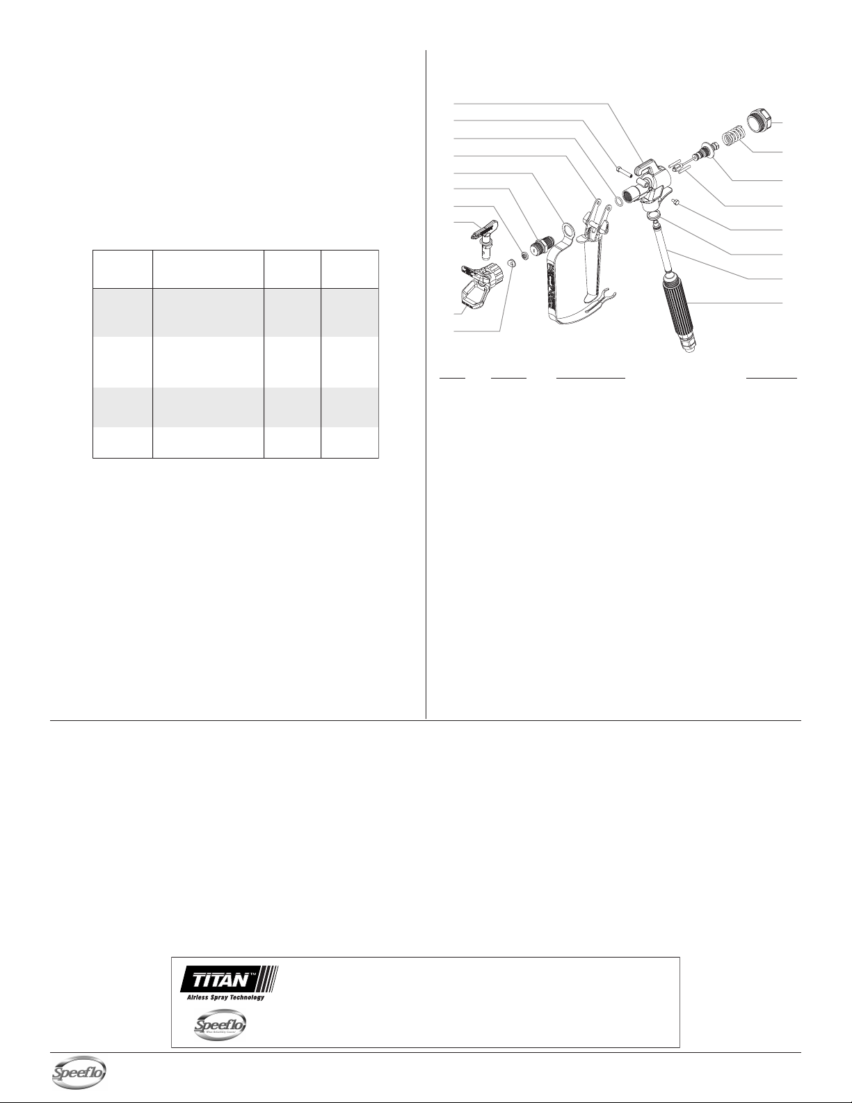
Parts List
Item Part # Description Quantity
1 550-253 Gun head...................................................1
2 550-254 Trigger screw, long ....................................1
3550-255 Diffuser o-ring ............................................1
4 550-256 Trigger assembly, 4-finger gun..................1
5 580-532 Trigger guard .............................................1
6 550-257 Diffuser, 7/8” (includes item 3)
7 651-020 Tip seal ......................................................1
8 661-517 Tip assembly (see accessory
catalog for additional sizes).......................1
9 661-012 Tip guard, 7/8”
10 651-040 Tip seal retainer.........................................1
11 550-258 End cap......................................................1
12 550-259 Packing spring...........................................1
13 550-264 Packing seal assembly..............................1
14 550-265 Retractor pin..............................................2
15 580-513 Trigger screw, short ...................................1
16 560-038 Handle seal................................................1
17 550-271 Filter, medium............................................1
18 550-266 Handle/swivel assembly, 1/4 NPS.............1
19 550-251 S-3 label (not shown).................................1
550-275 Gun repair kit, 7/8” diffuser
(includes items 3, 6, and 13)
1
2
3
4
5
6
7
8
9
10
12
13
14
15
16
17
18
11
This manual suits for next models
1
Table of contents
Other Speeflo Paint Sprayer manuals


Popular Paint Sprayer manuals by other brands


BUFFALO TURBINE
BUFFALO TURBINE BT-CS4 Original instructions and parts manual

Sagola
Sagola 450A instruction manual

Norac
Norac Rogator 1286C installation manual

Defort
Defort DSG-400 user manual

KIRKLAND
KIRKLAND Orvin Mounted Single Sprayer Use and maintenance manual

Graco
Graco FinishPro II 395 PC Operation, parts