Speeflo Gas Bare 459-350 User manual

1107 © 2006 Titan Tool Inc. All rights reserved. Form No. 313-2667B
Printed in the U. S. A.
NOTE: This manual contains important warnings
and instructions. Please read and retain for
reference.
Model Number:
Gas Bare 459-350
Gas Complete 459-355
PowrTwin 12000XLT DI
Do not use this equipment
before reading this manual!
Owner’s Manual
For professional use only

2 © Titan Tool Inc. All rights reserved.
This symbol indicates a hazardous situation, which, if
not not avoided could result in death or serious
injury.
To reduce the risks of fire or explosion, electrical
shock and the injury to persons, read and understand
all instructions included in this manual. Be familiar
with the controls and proper usage of the equipment.
WARNING: INJECTION INJURY
Ahigh pressure paint stream produced by this
equipment can pierce the skin and underlying tissues,
leading to serious injury and possible amputation. See
a physician immediately.
DO NOT TREAT AN INJECTION INJURY AS A SIMPLE CUT!
Injection can lead to amputation. See a physician immediately.
The maximum operating range of the sprayer is 3300 PSI / 22.8
MPa fluid pressure.
PREVENTION:
• NEVER aim the gun at any part of the body.
• Do not aim the gun at, or spray any person or animal.
• NEVER allow any part of the body to touch the fluid stream. DO
NOT allow body to touch a leak in the fluid hose.
• NEVER put your hand in front of the gun. Gloves will not
provide protection against an injection injury.
• ALWAYS lock the gun trigger, shut the pump off, and release
all pressure before servicing, cleaning the tip or guard,
changing tip, or leaving unattended. Pressure will not be
released by turning off the motor. The PRIME/SPRAY valve
or pressure bleed valve must be turned to their appropriate
positions to relieve system pressure. Refer to the
PRESSURE RELIEF PROCEDURE described in this manual.
• ALWAYS keep the tip guard in place while spraying. The tip
guard provides some protection but is mainly a warning device.
• ALWAYS remove the spray tip before flushing or cleaning the
system.
• Paint hose can develop leaks from wear, kinking and abuse.
A leak can inject material into the skin. Inspect the hose
before each use. Do not use hose to lift or pull equipment.
• NEVER use a spray gun without a working trigger lock and
trigger guard in place.
•All accessories must be rated at or above 3300 PSI / 22.8
MPa. This includes spray tips, guns, extensions, and hose.
• Do not leave the unit energized or under pressure while
unattended. When the unit is not in use, turn off the unit and
relieve the pressure in accordance with the PRESSURE
RELIEF PROCEDURE described in this manual.
•Verify that all connections are secure before operating the
unit. Unsecured parts may eject at great force or leak a high
pressure fluid stream causing severe injury.
• Always engage the trigger lock when not spraying. Verify the
trigger lock is functioning properly.
NOTE TO PHYSICIAN: Injection into the skin is a traumatic
injury. It is important to treat the injury as soon as
possible. DO NOT delay treatment to research toxicity.
Toxicity is a concern with some coatings injected directly
into the blood stream. Consultation with a plastic surgeon
or reconstructive hand surgeon may be advisable.
WARNING: HAZARDOUS VAPORS
Paints, solvents, insecticides, and other materials can be
harmful if inhaled or come in contact with the body.
Vapors can cause severe nausea, fainting, or poisoning.
PREVENTION:
• Use a respirator or mask if vapors can be inhaled.
Read all instructions supplied with the mask to be
sure it will provide the necessary protection.
• Wear protective eyewear.
• Wear protective clothing as required by coating manufacturer.
WARNING: EXPLOSION OR FIRE
Solvent and paint fumes can explode or ignite. Property
damage and/or severe injury can occur.
PREVENTION:
•Provide extensive exhaust and fresh air introduction to keep the
air within the spray area free from accumulation of flammable
vapors. Solvent and paint fumes can explode or ignite.
• Do not spray in a confined area.
• Avoid all ignition sources such as static electric sparks,
open flames, pilot lights, electrical appliances, and hot
objects. Connecting or disconnecting power cords or working
light switches can make sparks. Paint or solvent flowing
through the equipment is able to result in static electricity.
• Do not smoke in spray area.
• Fire extinguisher must be present and in good working order.
• Place pump at least 25 feet (7.62 meters) from the spray
object in a well ventilated area (add more hose if necessary).
Flammable vapors are often heavier than air. Floor area must
be extremely well ventilated. The pump contains arcing parts
that emit sparks and can ignite vapors.
• The equipment and objects in and around the spray area
must be properly grounded to prevent static sparks.
• Keep area clean and free of paint or solvent containers, rags
and other flammable materials.
• Use only conductive or grounded high pressure fluid hose.
Gun must be grounded through hose connections.
• For electric units — power cord must be connected to a
grounded circuit.
•Always flush unit into a separate metal container, at low pump
pressure, with spray tip removed. Hold gun firmly against side
of container to ground container and prevent static sparks.
• Follow the material and solvent manufacturer's warnings and
instructions. Know the contents of the paints and solvents
being sprayed. Read all Material Safety Data Sheets (MSDS)
and container labels provided with the paints and solvents.
Follow the paint and solvent manufacturer’s safety instructions.
• Use extreme caution with liquids having a flash point of less
than 21ºC (70ºF). Flashpoint is the temperature that a fluid
can produce enough vapors to ignite.
• Plastic can cause static sparks. Never hang plastic to
enclose a spray area. Do not use plastic drop cloths when
spraying flammable materials.
• Use lowest possible pressure to flush equipment.
• Do not spray onto pump assembly.
WARNING: EXPLOSION HAZARD DUE TO
INCOMPATIBLE MATERIALS
Will cause property damage or severe injury.
PREVENTION:
•Do not use materials containing bleach or chlorine.
• Do not use halogenated hydrocarbon solvents such as
bleach, mildewcide, methylene chloride and 1,1,1 -
trichloroethane. They are not compatible with aluminum.
• Contact your coating supplier about the compatibility of
material with aluminum.
IMPORTANT SAFETY INFORMATION • Read all safety information
before operating the equipment. SAVE THESE INSTRUCTIONS.

© Titan Tool Inc. All rights reserved. 3
WARNING: GENERAL
Can cause severe injury or property damage.
• Read all instructions and safety precautions before operating
equipment.
• Follow all appropriate local, state, and national codes
governing ventilation, fire prevention, and operation.
• The United States Government Safety Standards have been
adopted under the Occupational Safety and Health Act
(OSHA). These standards, particularly part 1910 of the
General Standards and part 1926 of the Construction
Standards should be consulted.
•Use only manufacturer authorized parts. User assumes all
risks and liabilities when using parts that do not meet the
minimum specifications and safety requirements of the pump
manufacturer.
• All hoses, fittings, and filter parts must be secured before
operating spray pump. Unsecured parts can eject at great
force or leak a high pressure fluid stream causing severe
injury.
• Before each use, check all hoses for cuts, leaks, abrasion or
bulging of cover. Check for damage or movement of
couplings. Immediately replace the hose if any of these
conditions exist. Never repair a paint hose. Replace it with
another grounded high-pressure hose.
• Do not kink or over-bend the hose. Airless hose can develop
leaks from wear, kinking and abuse. A leak can inject
material into the skin.
• Do not expose the hose to temperatures or pressures in
excess of those specified by manufacturer.
• Do not spray outdoors on windy days.
• Wear clothing to keep paint off skin and hair.
• Do not operate or spray near children. Keep children away
from the equipment at all times.
• Do not overreach or stand on an unstable support. Keep
effective footing and balance at all times.
• Use lowest possible pressure to flush equipment.
• Stay alert and watch what you are doing.
• Do not operate the unit when fatigued or under the influence
of drugs or alcohol.
• For electric units — Always unplug cord from outlet before
working on equipment.
• Do not use the hose as a strength member to pull or lift the
equipment.
•Do not lift by cart handle when loading or unloading.
Grounding Instructions
Electric models must be grounded. In the event of an electrical
short circuit, grounding reduces the risk of electric shock by
providing an escape wire for the electric current. This product is
equipped with a cord having a grounding wire with an appropriate
grounding plug. The plug must be plugged into an outlet that is
properly installed and grounded in accordance with all local codes
and ordinances.
DANGER — Improper installation of the grounding plug can result
in a risk of electric shock. If repair or replacement of the cord or
plug is necessary, do not connect the green grounding wire to
either flat blade terminal. The wire with insulation having a green
outer surface with or without yellow stripes is the grounding wire
and must be connected to the grounding pin.
Check with a qualified electrician or serviceman if the grounding
instructions are not completely understood, or if you are in doubt
as to whether the product is properly grounded. Do not modify the
plug provided. If the plug will not fit the outlet, have the proper
outlet installed by a qualified electrician.
IMPORTANT - Use only a 3-wire extension cord that has a 3-
blade grounding plug and a 3-slot receptacle that will accept
the plug on the product. Make sure your extension cord is in
good condition. When using an extension cord, be sure to
use one heavy enough to carry the current your product will
draw. An undersized cord will cause a drop in line voltage
resulting in loss of power and overheating. A 12 gauge cord is
recommended. If an extension cord is to be used outdoors, it
must be marked with the suffix W-A after the cord type
designation. For example, a designation of SJTW-A would
indicate that the cord would be appropriate for outdoor use.
Gasoline Engine Safety
The engine exhaust from this unit contains chemicals
known to the State of California to cause cancer,
birth defects, or other reproductive harm.
•Honda engines are designed to give safe and dependable
service if operated according to instructions. Read and
understand the Honda Owner's Manual before operating the
engine. Failure to do so could result in personal injury or
equipment damage.
• To prevent fire hazards and to provide adequate ventilation,
keep the engine at least 1 meter (3 feet) away from buildings
and other equipment during operation. Do not place
flammable objects close to the engine.
• Children and pets must be kept away from the area of
operation due to a possibility of burns from hot engine
components or injury from any equipment the engine may be
used to operate.
• Know how to stop the engine quickly, and understand the
operation of all controls. Never permit anyone to operate the
engine without proper instructions.
• Gasoline is extremely flammable and is explosive under
certain conditions.
• Refuel in a well-ventilated area with the engine stopped. Do
not smoke or allow flames or sparks in the refueling area or
where gasoline is stored.
• Do not overfill the fuel tank. After refueling, make sure the
tank cap is closed properly and securely.
• Be careful not to spill fuel when refueling. Fuel vapor or
spilled fuel may ignite. If any fuel is spilled, make sure the
area is dry before starting the engine.
• Never run the engine in an enclosed or confined area.
Exhaust contains poisonous carbon monoxide gas; exposure
may cause loss of consciousness and may lead to death.
• The muffler becomes very hot during operation and remains
hot for a while after stopping the engine. Be careful not to
touch the muffler while it is hot. To avoid severe burns or fire
hazards, let the engine cool before transporting it or storing it
indoors.
• Never ship/transport unit with gasoline in the tank.
DO NOT use this equipment to spray water or acid.
IMPORTANT: Do not lift by cart handle when loading or
unloading.
Grounded Outlet
Grounding Pin
Cover for grounded outlet box
IMPORTANT SAFETY INFORMATION • Read all safety information
before operating the equipment. SAVE THESE INSTRUCTIONS.

Table of Contents
Safety Precautions . . . . . . . . . . . . . . . . . . . . . . . . . . . . . . . 2-3
Grounding Instructions . . . . . . . . . . . . . . . . . . . . . . . . . . . . . 3
Gasoline Engine Safety . . . . . . . . . . . . . . . . . . . . . . . . . . . . 3
Specifications. . . . . . . . . . . . . . . . . . . . . . . . . . . . . . . . . . . . . 4
Introduction . . . . . . . . . . . . . . . . . . . . . . . . . . . . . . . . . . . . . . 5
Operation . . . . . . . . . . . . . . . . . . . . . . . . . . . . . . . . . . . . . . . . 5
Fueling . . . . . . . . . . . . . . . . . . . . . . . . . . . . . . . . . . . . . . . . . 5
Operating the Swing Cart. . . . . . . . . . . . . . . . . . . . . . . . . . . 6
Setup . . . . . . . . . . . . . . . . . . . . . . . . . . . . . . . . . . . . . . . . . . 6
Preparing to Paint. . . . . . . . . . . . . . . . . . . . . . . . . . . . . . . . . 8
Painting. . . . . . . . . . . . . . . . . . . . . . . . . . . . . . . . . . . . . . . . . 8
Pressure Relief Procedure . . . . . . . . . . . . . . . . . . . . . . . . . . 9
Cleanup . . . . . . . . . . . . . . . . . . . . . . . . . . . . . . . . . . . . . . . . . . 9
Cleaning a Clogged Tip . . . . . . . . . . . . . . . . . . . . . . . . . . . 10
Maintenance . . . . . . . . . . . . . . . . . . . . . . . . . . . . . . . . . . . . . 10
Daily Maintenance . . . . . . . . . . . . . . . . . . . . . . . . . . . . . . . 10
Maintaining the Filter Assembly . . . . . . . . . . . . . . . . . . . . . 11
Maintaining the Hydraulic System . . . . . . . . . . . . . . . . . . . 11
Maintaining the Fluid Section . . . . . . . . . . . . . . . . . . . . . . . 11
Basic Engine Maintenance (gas engine) . . . . . . . . . . . . . . 12
Replacing the Motor Brushes (electric motor) . . . . . . . . . . 12
Troubleshooting . . . . . . . . . . . . . . . . . . . . . . . . . . . . . . . . . . 13
Airless Gun. . . . . . . . . . . . . . . . . . . . . . . . . . . . . . . . . . . . . 13
Fluid Section. . . . . . . . . . . . . . . . . . . . . . . . . . . . . . . . . . . . 13
Hydraulic Motor . . . . . . . . . . . . . . . . . . . . . . . . . . . . . . . . . 14
Spray Patterns . . . . . . . . . . . . . . . . . . . . . . . . . . . . . . . . . . 15
Parts Lists and Service Instructions . . . . . . . . . . . . . . . . . 20
Main Assembly . . . . . . . . . . . . . . . . . . . . . . . . . . . . . . . . . . 20
Cart Assembly . . . . . . . . . . . . . . . . . . . . . . . . . . . . . . . . . . 21
Belt Guard Assembly . . . . . . . . . . . . . . . . . . . . . . . . . . . . . 21
Hydraulic Motor . . . . . . . . . . . . . . . . . . . . . . . . . . . . . . . . . 22
Fluid Section. . . . . . . . . . . . . . . . . . . . . . . . . . . . . . . . . . . . 24
Hydraulic System . . . . . . . . . . . . . . . . . . . . . . . . . . . . . . . . 26
Gas Convertokit . . . . . . . . . . . . . . . . . . . . . . . . . . . . . . . . . 27
DC— Electric Convertokit. . . . . . . . . . . . . . . . . . . . . . . . . . 27
Bleed Valve Assembly . . . . . . . . . . . . . . . . . . . . . . . . . . . . 28
Filter Assembly . . . . . . . . . . . . . . . . . . . . . . . . . . . . . . . . . . 28
Gun Manifold Assemblies (optional). . . . . . . . . . . . . . . . . . 29
SAE O-Ring Fitting Installation. . . . . . . . . . . . . . . . . . . . . . 30
Accessories and Service Kits. . . . . . . . . . . . . . . . . . . . . . . 30
Airless Tip Selection . . . . . . . . . . . . . . . . . . . . . . . . . . . . . . 30
Warranty . . . . . . . . . . . . . . . . . . . . . . . . . . . . . . . . . . . . . . . . 32
4 © Titan Tool Inc. All rights reserved.
Specifications
Gas Sprayer
Gallons per minute (GPM)...............3.15 (11.9 LPM)
Cycle rate per gallon........................40 (10.5 cycles/liter)
Maximum tip sizes ...........................1 gun = .058”
2 guns = .040”
3 guns = .034”
4 guns = .030”
5 guns = .026”
6 guns = .024”
Maximum pressure ..........................3300 PSI (22.8 MPa)
Power...............................................Honda 9 HP, 4-stroke,
single cylinder, overhead
valve engine w/oil alert
Fuel capacity....................................1.6 US gallons
(approx. 2.5 hours run time)
Halogenated solvent compatible......Yes
Weight..............................................188 lbs. (85.3 kg.)
Inlet paint filter .................................10 mesh “Rock Catcher”
Outlet paint filter...............................50 mesh, 18 in.2
Pump inlet........................................1” NPT(F)
Pump outlet......................................1/2” NPT(F) to paint filter
Paint filter hose connections............3/8” NPS(M)
3/8” NPT(F) (plugged)
Dimensions ......................................46" L (116.8 cm) x
27" W (68.6 cm) x
34" H (86.6 cm)
Fluid section wetted parts:
Electroless nickel plated ductile iron, electroless nickel plated
carbon steel, stainless steel, tungsten carbide, Teflon, thiokol
impregnated leather, ultra high molecular weight polyethylene.
Electric Sprayer
Gallons per minute (GPM)...............1.25 (4.7 LPM)
Cycle rate per gallon........................40 (10.5 cycles/liter)
Maximum tip sizes ...........................1 gun = .036”
2 guns = .026”
3 guns = .019”
Maximum pressure ..........................3300 psi (22.8 MPa)
Power...............................................2 HP DC Motor,
115V 15.5A,
overload protected
Halogenated solvent compatible......Yes
Weight..............................................192 lbs. (87.1 kg.)
Inlet paint filter .................................10 mesh “Rock Catcher”
Outlet paint filter...............................50 mesh, 18 in.2
Pump inlet........................................1” NPT(F)
Pump outlet......................................1/2” NPT(F) to paint filter
Paint filter hose connections............3/8” NPS(M)
3/8” NPT(F) (plugged)
Dimensions ......................................46" L (116.8 cm) x
27" W (68.6 cm) x
34" H (86.6 cm)
Fluid section wetted parts:
Electroless nickel plated ductile iron, electroless nickel plated
carbon steel, stainless steel, tungsten carbide, Teflon, thiokol
impregnated leather, ultra high molecular weight polyethylene.

Introduction
Congratulations on having selected the finest airless sprayer
available in the world. Speeflo piston pumps are tireless
workhorses — so tough they are virtually indestructible, even
under the most severe service. Speeflo designs and builds
equipment with superior quality and reliability. Equipment that
will last for years with minimal maintenance and downtime.
This equipment will make you money year after year. We
thank you for your purchase and welcome you to our large
and growing family of Speeflo users.
The unique ability of this PowrTwin to operate with either gas
or electric power provides you with the flexibility to work
indoors or outside where no electricity is available.
Hydraulic drive makes possible the longest stroke and slowest
cycling pumps in the industry, which translates into low
maintenance and longer life. Electric sprayers operate quietly
with no motor starting and stopping.
This PowrTwin is equipped with Speeflo's exclusive fluid
pump. This technology will give you significantly longer rod,
cylinder, and packing life than any other sprayer built in the
world. This double ball piston pump employs a dependable
and durable time-tested design. All pumps use thick, stainless
steel rod and cylinder parts. Highly polished parts reduce
friction, extend packing life, and avoid damage from corrosion
and abrasion. More than 100,000 of these pumps are in
operation around the world.
This PowrTwin offers other cost saving features:
• Freeze-proof pressure control
•Choice of power — gas, electric, or both
•Tungsten carbide reversible valve seats
• Self-adjusting packings
•Exclusive hand-tight swivel foot valve
• Large capacity inline paint filter
• Waterborne compatible
• "Floating Ball" pressure bleed valve
You have made an excellent choice. We know you will be
pleased with your new PowrTwin. Thanks again for selecting
Speeflo. We appreciate your business.
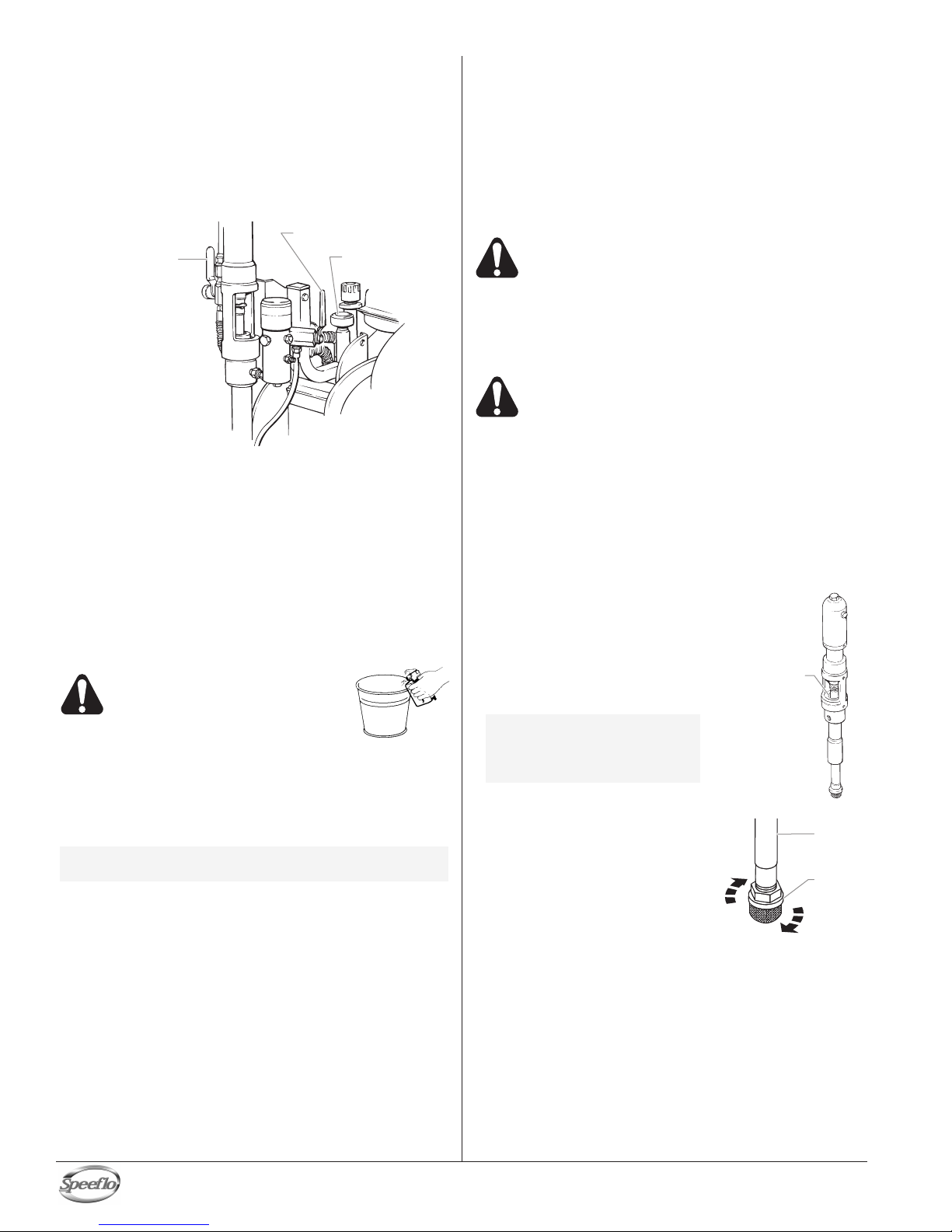
Bleed Valve
Motor/Pump
Assembly
Outlet Fitting
Pressure Control
Knob Hydraulic
Fluid Cap/
Dipstick
Gas Tank
Filter
Siphon Tube
Bleed Hose
Hydraulic
Shut-Off
Valve
Operation
Fueling (gas engine)
Gasoline is extremely flammable and is explosive
under certain conditions.
• ALWAYS turn the engine off before refueling.
• Refuel in a well-ventilated area.
• Do not smoke or allow flames or sparks in the refueling
area or where gasoline is stored.
•Do not overfill the fuel tank. After refueling, make sure
the tank cap is closed properly and securely.
• Be careful not to spill fuel when refueling. Spilled fuel or
fuel vapor may ignite. If any fuel is spilled, make sure the
area is dry before starting the engine.
• Avoid repeated or prolonged contact with skin or
breathing of vapor.
• Keep out of the reach of children.
Fuel Specifications
• Use automotive gasoline that has a pump octane number
of 86 or higher, or that has a research octane number of 91
or higher. Use of a lower octane gasoline can cause
persistent "pinging" or heavy "spark knock" (a metallic
rapping noise) which, if severe, can lead to engine damage.
• Unleaded fuel produces fewer engine and spark plug
deposits and extends the life of the exhaust system
components.
• Never use stale or contaminated gasoline or an
oil/gasoline mixture. Avoid getting dirt, dust, or water in
the fuel tank.
Gasolines Containing Alcohol
If you decide to use a gasoline containing alcohol (gasohol),
be sure its octane rating is at least as high as that
recommended by the engine manufacturer. There are two
types of "gasohol": one containing ethanol, and the other
containing methanol. Do not use gasohol that contains more
than 10% ethanol. Do not use gasoline containing methanol
(methyl or wood alcohol) that does not also contain co-
solvents and corrosion inhibitors for methanol. Never use
gasoline containing more than 5% methanol, even if it has co-
solvents and corrosion inhibitors.
NOTE: Fuel system damage or engine performance
problems resulting from the use of fuels that
contain alcohol is not covered under the
warranty. The engine manufacturer cannot
endorse the use of fuels containing methanol
since evidence of their suitability is incomplete
at this time.
Before buying gasoline from an unfamiliar
station, try to find out if the gasoline contains
alcohol. If it does, confirm the type and
percentage of alcohol used. If you notice any
undesirable operating characteristics while using
a gasoline that contains alcohol, or one that you
think contains alcohol, switch to a gasoline that
you know does not contain alcohol.
NOTE: If "spark knock" or "pinging" occurs at a
steady engine speed under normal load,
change brands of gasoline. If spark knock or
pinging persists, consult an authorized dealer
of the engine manufacturer. Failure to do so is
considered misuse, and damage caused by
misuse is not covered by the engine
manufacturer’s limited warranty.
Occasionally you may experience light spark
knock while operating under heavy loads. This
is no cause for concern, it simply means your
engine is operating efficiently.
© Titan Tool Inc. All rights reserved. 5

Operating the Swing Cart
Use caution when operating the swing cart. Keep
fingers and feet clear of moving parts.
The swing cart allows the motor/pump assembly to be rotated
between two positions.
Position #1: Working Position
The vertical position of the motor/pump assembly is the
working position. This position allows complete submersion of
the siphon tube on the fluid section into a paint bucket. The
maximum height paint bucket that can be used is 28 1/8” (71.4
cm).
Position #2: Transporting Position
The horizontal position of the motor/pump assembly is the
transporting position. This position allows easy removal of the
paint bucket and a sprayer height of 30” (76.2 cm) for ease of
transportation.
Use the following procedure to change the position of the
motor/pump assembly.
1. Holding the handle grip with one hand, pull the locking pin
out of the locking hole on the cart with the other hand.
This allows the motor/pump assembly mounted on the
swing cart frame to move from one position to the other.
2. Let go of the locking pin once it is free of the locking hole.
3. Move the motor/pump assembly to the desired position.
The locking pin is spring loaded and will automatically
engage the locking hole on the swing cart at the new
position.
6 © Titan Tool Inc. All rights reserved.
Setup
Read, understand, and follow all warnings before
starting or operating this sprayer.
1. Make sure the bleed hose is threaded into the bleed
valve. It has factory installed Teflon tape on the fitting and
should be tightened wrench tight.
2. Attach a minimum of 50’ of nylon airless spray hose to the
sprayer. Do not use Teflon tape or thread sealant on the
spray hose connection.
3. Attach an airless spray gun to the spray hose. Do not
attach the tip to the spray gun yet. Remove the tip if it is
already attached.
a. To use two guns, remove the plug from the second gun
outlet on the filter assembly. Connect a hose and gun
to the outlet.
4. Fill the oil cup 1/2 full with Speeflo
Piston Lube (P/N 314-480) supplied
by the factory. This extends packing life.
5. Check the hydraulic fluid level daily before starting the
sprayer. The hydraulic fluid level should be at the “Full”
mark on the dipstick. Refer to the Maintenance section of
this manual for hydraulic system maintenance
instructions.
IMPORTANT: Use of Speeflo's Coolflo™ Hydraulic Fluid
(P/N 430-361) is mandatory in the hydraulic system. Do
not use any other hydraulic fluid. Use of any other
hydraulic fluid may seriously damage the hydraulic
system and will void the warranty.
NOTE: The gas sprayer is
engineered to handle up
to 6 guns with .024" tips
and the electric sprayer
is engineered to handle
up to 3 guns with .019”
tips. For multiple gun
operation, connect a
multiple gun manifold to
the single gun outlet.
Connect a hose and gun
to each outlet. Make
sure the second gun
outlet remains plugged.
Multiple Gun
Manifold
Bleed Valve
Filter
Bleed Hose

© Titan Tool Inc. All rights reserved. 7
6. For gas models, check the engine oil level daily before
starting the sprayer. The gasoline engine oil level is
determined by the engine manufacturer. Refer to the
engine manufacturer’s service manual supplied with this
sprayer.
7. For electric models, use a 20 amp service outlet. Always
locate the electric model within 10 to 15 feet of the service
outlet. Use a short electric cable and a long paint hose.
Any extension cord will create some voltage drop. If an
extension cord is necessary, use only a grounded 3-wire
#12 gauge extension cord.
8. Make sure the sprayer is grounded. All sprayers are
equipped with a grounding lug. A grounding cable (not
supplied) should be used to connect the sprayer to a true
earth ground. Check your local electrical regulations for
detailed grounding instructions. See the Accessories and
Service Kits section near the back of this manual for
grounding cable ordering information.
Proper grounding is important. This applies to
both gas and electric powered models. The
passage of some materials through the nylon fluid
hose will build up a static electric charge, which if
discharged, could ignite solvent vapors present
and create an explosion.
9. Strain all paints with a nylon strainer to ensure trouble
free operation and freedom from frequent cleaning of the
inlet screen and gun filter.
10 Make sure the spray area is well ventilated to prevent
hazardous operation with volatile solvents or exhaust
fumes.
If lacquer or other flammable materials are to be
sprayed, ALWAYS locate the sprayer outside the
immediate spraying area. Failure to do so may
cause an explosion.
11. Locate the sprayer outside the immediate spraying area to
avoid clogged air intake of the engine or electric motor
with overspray.
NOTE: If the sprayer is being operated in an area that
is overloaded by other appliances or low
voltage conditions, it is important to start the
sprayer "unloaded." Tip the electric motor
forward so that the belt is loosened and the
motor starts without full load. This reduces the
amperage draw on starting and may avoid
tripping the circuit breaker.
Preparing a New Sprayer
If this sprayer is new, it is shipped with test fluid in the fluid
section to prevent corrosion during shipment and storage.
This fluid must be thoroughly cleaned out of the system with
mineral spirits before you begin spraying.
IMPORTANT: Always keep the trigger lock on the spray
gun in the locked position while preparing the system.
1. Place the siphon tube into a container of mineral spirits.
2. Place the bleed hose into a metal waste container.
3. Set the pressure to minimum by turning the pressure
control knob fully counterclockwise.
4. Open the hydraulic shut-off valve located on the hydraulic
pressure hose. The handle should be in line with the hose.
5. Open the bleed valve by rotating the bleed valve handle
fully counterclockwise.
6. Start the engine or turn on the electric motor.
a. To start the gas
engine,
• move the fuel
valve lever to
the open
position,
• move the
throttle lever to
its middle point,
• move the choke
lever to the
closed position
for a cold engine or to the open position for a warm
engine,
• turn the engine switch to the ON position, and
• pull the starter rope briskly until the engine starts.
b. To start the electric motor, move the ON/OFF switch to
the ON position.
7. Turn the pressure control knob clockwise approximately
1/3 of the way down to increase pressure until the sprayer
cycles evenly and solvent flows freely from the bleed hose.
8. Allow the sprayer to run for 15–30 seconds to flush the
test fluid out through the bleed hose and into the waste
container.
9. Turn off the sprayer.
a. To turn off the gas engine,
•set the pressure to minimum by turning the pressure
control knob fully counterclockwise,
•move the throttle lever to the slow position, and
• turn the engine switch to the OFF position.
b. To turn off the electric motor,
• set the pressure to minimum by turning the pressure
control knob fully counterclockwise,
• move the ON/OFF switch to the OFF position.
Fuel Valve
Lever
Choke Lever
Engine
Switch
Throttle
Lever
Starter Rope
Hydraulic Shut-off
Valve (in open
position)
Pressure Control
Knob
Bleed Valve

Preparing to Paint
Before painting, it is important to make sure that the fluid in the
system is compatible with the paint that is going to be used.
IMPORTANT: Always keep the trigger lock on the spray
gun in the locked position while preparing the system.
1. Place the siphon tube into a container of the appropriate
solvent.
2. Place the bleed hose into a metal waste container.
3. Set the pressure to minimum by turning the pressure
control knob fully counterclockwise.
4. Open the hydraulic shut-off valve located on the hydraulic
pressure hose. The handle should be in line with the hose.
5. Open the bleed valve by rotating the bleed valve handle
fully counterclockwise.
6. Start the engine or turn on the electric motor.
a. To start the gas engine,
• move the fuel valve lever to the open position,
• move the throttle lever to its middle point,
• move the choke lever to the closed position for a
cold engine or to the open position for a warm
engine,
• turn the engine switch to the ON position, and
• pull the starter rope briskly until the engine starts.
b. To start the electric motor, move the ON/OFF switch to
the ON position.
7. Turn the pressure control knob clockwise approximately
1/3 of the way down to increase pressure until the sprayer
cycles evenly and solvent flows freely from the bleed hose.
8. Allow the sprayer to run for 15–30 seconds to flush the
test fluid out through the bleed hose and into the waste
container.
9. Turn off the sprayer.
a. To turn off the gas engine,
• set the pressure to minimum by turning the pressure
control knob fully counterclockwise,
• move the throttle lever to the slow position, and
• turn the engine switch to the OFF position.
b. To turn off the electric motor,
• set the pressure to minimum by turning the pressure
control knob fully counterclockwise,
•move the ON/OFF switch to the OFF position.
10. Close the bleed valve by rotating the bleed valve handle
fully clockwise.
11. Start the engine or turn on the electric motor.
12. Turn the pressure control knob clockwise approximately
1/3 of the way down to increase pressure.
13. Unlock the gun by turning the gun trigger lock to the
unlocked position.
NOTE: Make sure that the spray gun does not have a
tip or tip guard installed.
NOTE: If you are spraying a water-based latex, flush
with warm, clean water. If you are using any
other material, check with the material
manufacturer for a compatible solvent.
NOTE: Incompatible fluids and paint may cause the
valves to become stuck closed, which would
require disassembly and cleaning of the
sprayer’s fluid section.
8 © Titan Tool Inc. All rights reserved.
Ground the gun by holding it
against the edge of the metal
container while flushing. Failure
to do so may lead to a static
electric discharge, which may
cause a fire.
14. Trigger the gun into the metal waste container until the old
solvent is gone and fresh solvent is coming out of the gun.
15. Lock the gun by turning the gun trigger
lock to the locked position.
16. Set down the gun and increase the
pressure by turning the pressure control
knob slowly clockwise.
17. Check the entire system for leaks. If
leaks occur, follow the “Pressure Relief
Procedure” in this manual before
tightening any fittings or hoses.
18. Follow the “Pressure Relief Procedure” in this manual
before changing from solvent to paint.
Be sure to follow the pressure relief procedure
when shutting the sprayer down for any purpose,
including servicing or adjusting any part of the
spray system, changing or cleaning spray tips, or
preparing for cleanup.
Painting
1. Place the siphon tube into a container of paint.
2. Place the bleed hose into a metal waste container.
3. Set the pressure to minimum by turning the pressure
control knob fully counterclockwise.
4. Open the hydraulic shut-off valve located on the hydraulic
pressure hose. The handle should be in line with the hose.
5. Open the bleed valve by rotating the bleed valve handle
fully counterclockwise.
6. Start the engine or turn on the electric motor.
a. To start the gas engine,
• move the fuel
valve lever to
the open
position,
• move the
throttle lever to
its middle point,
• move the choke
lever to the
closed position
for a cold
engine or to the
open position
for a warm engine,
• turn the engine switch to the ON position, and
• pull the starter rope briskly until the engine starts.
Fuel Valve
Lever
Choke Lever
Engine
Switch
Throttle
Lever
Starter Rope
Hydraulic Shut-off
Valve (in open
position)
Pressure Control
Knob
Bleed Valve
Trigger lock in
locked position.

b. To start the electric motor, move the ON/OFF switch to
the ON position.
7. Turn the pressure control knob clockwise approximately
1/3 of the way down to increase pressure until the sprayer
cycles evenly and paint flows freely from the bleed hose.
8. Turn off the sprayer.
a. To turn off the gas engine,
• set the pressure to minimum by turning the pressure
control knob fully counterclockwise,
•move the throttle lever to the slow position, and
• turn the engine switch to the OFF position.
b. To turn off the electric motor,
• set the pressure to minimum by turning the pressure
control knob fully counterclockwise,
• move the ON/OFF switch to the OFF position.
9. Remove the bleed hose from the waste container and
place it into the container of paint.
10. Close the bleed valve by rotating the bleed valve handle
fully clockwise.
11. Start the engine or turn on the electric motor.
12. Turn the pressure control knob clockwise approximately
1/3 of the way down to increase pressure.
13. Unlock the gun by turning the gun trigger lock to the
unlocked position.
Ground the gun by holding it
against the edge of the metal
container while flushing. Failure
to do so may lead to a static
electric discharge, which may
cause a fire.
14. Trigger the gun into the metal waste container until all air
and solvent is flushed from the spray hose and paint is
flowing freely. from the gun.
15. Lock the gun by turning the gun trigger
lock to the locked position.
16. Turn off the sprayer.
17. Attach tip guard and tip to the gun as
instructed by the tip guard or tip manuals.
POSSIBLE INJECTION HAZARD.
Do not spray without the tip guard in place. Never
trigger the gun unless the tip is in either the spray
or the unclog position. Always engage the gun
trigger lock before removing, replacing or
cleaning tip.
18. Start the engine or turn on the electric motor.
19. Increase the pressure by turning the pressure control
knob slowly clockwise and test the spray pattern on a
piece of cardboard. Adjust the pressure control knob until
the spray from the gun is completely atomized.
NOTE: Turning the pressure up higher then needed to
atomize the paint will cause premature tip wear
and additional overspray.
Trigger lock in
locked position.
Pressure Relief Procedure
Be sure to follow the pressure relief procedure
when shutting the sprayer down for any purpose,
including servicing or adjusting any part of the
spray system, changing or cleaning spray tips, or
preparing for cleanup.
1. Lock the gun by turning the gun trigger
lock to the locked position.
2. Turn off the sprayer.
a. To turn off the gas engine,
• set the pressure to minimum by
turning the pressure control knob
fully counterclockwise,
• move the throttle lever to the slow
position, and
• turn the engine switch to the OFF position.
b. To turn off the electric motor,
• set the pressure to minimum by turning the pressure
control knob fully counterclockwise,
• move the ON/OFF switch to the OFF position.
3. Close the hydraulic shut-off valve on the hydraulic
pressure hose.
4. Unlock the gun by turning the gun trigger lock to the
unlocked position.
5. Hold the metal part of the gun firmly to
the side of a metal waste container to
ground the gun and avoid a build up of
static electricity.
6. Trigger the gun to remove any pressure
that may still be in the hose.
7. Lock the gun by turning the gun trigger lock to the locked
position.
8. Place the bleed hose into the metal waste container.
9. Open the bleed valve by rotating the bleed valve handle
fully counterclockwise.
Cleanup
Special cleanup instructions for use with
flammable solvents:
•Always flush spray gun preferably outside
and at least one hose length from spray pump.
• If collecting flushed solvents in a one gallon metal
container, place it into an empty five gallon container, then
flush solvents.
• Area must be free of flammable vapors.
•Follow all cleanup instructions.
IMPORTANT: The sprayer, hose, and gun should be
cleaned thoroughly after daily use. Failure to do so
permits material to build up, seriously affecting the
performance of the sprayer.
Always spray at minimum pressure with the gun
nozzle tip removed when using mineral spirits or
any other solvent to clean the sprayer, hose, or
gun. Static electricity buildup may result in a fire
or explosion in the presence of flammable vapors.
1. Follow the “Pressure Relief Procedure” found in the
Operation section of this manual.
2. Remove the gun tip and tip guard and clean with a brush
using the appropriate solvent.
Trigger lock in
locked position.
© Titan Tool Inc. All rights reserved. 9
3. Place the siphon tube into a container of the appropriate
solvent.
IMPORTANT: Use only compatible solvents when cleaning out
oil based enamels, lacquers, coal tar, and epoxies. Check
with the fluid manufacturer for the recommended solvent.
4. Place the bleed hose into a metal waste container.
5. Set the pressure to minimum by turning the pressure
control knob fully counterclockwise.
6. Open the hydraulic shut-off valve located on the hydraulic
pressure hose. The handle should be in line with the hose.
7. Open the bleed valve by rotating the bleed valve handle
fully counterclockwise.
8. Start the engine or turn on the electric motor.
9. Allow the solvent to circulate through the sprayer and
flush the paint out of the bleed hose into the metal waste
container.
10. Turn off the sprayer.
11. Close the bleed valve by rotating the bleed valve handle
fully clockwise.
12. Start the engine or turn on the electric motor.
Ground the gun by holding it
against the edge of the metal
container while flushing. Failure to
do so may lead to a static electric
discharge, which may cause a fire.
13. Trigger the gun into the metal waste container until the
paint is flushed out of the hose and solvent is coming out
of the gun.
14. Continue to trigger the spray gun into the waste container
until the solvent coming out of the gun is clean.
15. Follow the “Pressure Relief Procedure” found in the
Operation section of this manual.
16. Store the sprayer in a clean, dry area.
IMPORTANT: Do not store the sprayer under pressure.
NOTE: For long-term or cold weather storage, pump
mineral sprits through the entire system.
Hydraulic Shut-off
Valve (in open
position)
Pressure Control
Knob
Bleed Valve
10 © Titan Tool Inc. All rights reserved.
Cleaning a Clogged Tip
1. Follow the “Pressure Relief Procedure” in the Operation
section of this manual.
2. If the tip clogs, rotate the tip handle 180° until the arrow
on the handle is facing the opposite of the spray direction
and the handle clicks in the reverse position.
3. Trigger the gun once so that the pressure can blow the
clog out. NEVER use the tip in the reverse position for
more than ONE trigger pull at a time. This procedure can
be repeated until the tip is free of clogging.
The flow from the spray tip is at very high
pressure. Contact with any body part may be
dangerous. Do not place finger on gun outlet. Do
not point the gun at any person. Never operate
the spray gun without the proper tip guard.
Maintenance
Before proceeding, follow the Pressure Relief
Procedure outlined previously in this manual.
Additionally, follow all other warnings to reduce
the risk of an injection injury, injury from moving
parts or electric shock. Always unplug the
sprayer before servicing!
Daily Maintenance
Two daily procedures are required for routine operator
maintenance on this sprayer:
1. Lubricating the upper packings.
2. Cleaning the rock catcher.
Lubricating the Upper Packings
1. Clean out the paint that has
seeped past the upper packings
into the packing oil cup above the
fluid section.
2. Fill the packing oil cup 1/2 full
with Piston Lube (P/N 314-480)
supplied by the factory. This will
extend packing life.
Cleaning the Inlet Screen
The inlet screen will clog and must be
cleaned at least once a day.
1. Loosen and remove the inlet
screen from the siphon tube.
2. Clean thoroughly with the
appropriate solvent.
Siphon
Tube
Inlet
Screen
NOTE: Do not over-fill the oil
cup so that it
overflows and drips
into the paint.
Packing Oil
Cup

Maintaining the Filter Assembly
Clean the filter regularly. Dirty or clogged filters can greatly
reduce filtering ability and cause a number of system problems
including poor spray patterns, clogged spray tips, etc.
Cleaning
To clean the filter, perform the following procedure.
1. Follow the “Pressure Relief Procedure” found in the
Operation section of this manual.
2. Remove the filter cap assembly
and spring.
3. Pull the filter element with ball
straight out of the filter body.
4. Clean inside the filter body,
filter element with ball, and filter
cap assembly using the
appropriate solvent.
Inspection
Inspect all parts of the filter assembly before reassembly.
1. Inspect the ball inside the filter element. If the ball has
pressure cuts or scratches, replace the filter element.
a. If the ball is cut, remove the Teflon o-ring using an o-
ring pick and remove the carbide seat.
b. Check the seat for nicks or grooves. If the seat is
damaged, replace.
2. Remove the spring from the spring guide on the filter cap.
a. Measure the length of the spring uncompressed. If it
measures less the 3/4” from end to end, replace.
b. Push the spring back onto the spring guide until it
“snaps” back into position.
3. Inspect the two Teflon gaskets and the Teflon o-ring for
deformity, nicks, or cuts. Replace, if needed.
Reassembly
After cleaning and inspecting all parts, reassemble the filter.
1. Place the carbide seat into the filter body. Make sure the
beveled side of the seat is facing up.
2. Place the Teflon o-ring into the groove on the outer
diameter of the carbide seat.
3. Place the filter element with ball into the filter body.
4. Push the spring back onto the spring guide of the filter cap
until it “snaps” back into position, if not already done.
5. Place the thin Teflon gasket onto the step at the top of the
filter body.
6. Place the thick Teflon gasket onto the top of the thin
gasket.
7. Tighten the filter cap assembly onto the filter body.
NOTE: The top and bottom of the filter element with
ball are identical.
NOTE: The Teflon gaskets, Teflon o-ring, and spring
are packaged in Filter Service Kit P/N 930-050.
NOTE: Removal of the Teflon o-ring will damage the
o-ring and require replacement.
NOTE: Use care in handling
parts as dirt, debris,
scratches, or nicks
may prevent o-rings or
gaskets from sealing.
This filter element
filters from the inside
out. Be sure to clean
the filter element
thoroughly on the
inside. Soak in
solvent to loosen
hardened paint or
replace.
Filter Cap
Assembly
Filter
Element
w/Ball
Teflon Gasket
(thick)
Teflon Gasket
(thin)
Teflon O-ring
Carbide Seat
Filter Body
Spring
Maintaining the Hydraulic System
IMPORTANT: Use of Speeflo's Coolflo™ Hydraulic Fluid is
mandatory in the PowrTwin hydraulic system. Do not use
any other hydraulic fluid. Use of any other hydraulic fluid
may seriously damage the hydraulic system and will void
the warranty.
1. Check the hydraulic fluid daily. It should be at the “Full”
mark on the dipstick. If it is low, add only Speeflo
Coolflo™ Hydraulic Fluid (P/N 430-361). Never add or
change hydraulic fluid except in a clean, dust-free area.
Contamination of the hydraulic fluid will shorten hydraulic
pump life and may void warranty.
2. Change the hydraulic fluid every twelve months. Drain the
old fluid from the tank and fill with 4 quarts of Speeflo
Coolflo™ Hydraulic Fluid. Start the sprayer at just enough
pressure to operate the fluid section. Run the sprayer at
this low pressure for at least 5 minutes. This removes air
from the system. Check the fluid level after this
procedure. Do not over-fill.
3. The hydraulic system has an external, replaceable
hydraulic filter. Change the filter every twelve months.
4. The hydraulic pump should not be serviced in the field. If
service on the hydraulic pump is required, it must be
returned to Speeflo.
Maintaining the Fluid Section
If the sprayer is going to be out of service for an extended
period of time, it is recommended that following cleanup a
mineral spirits and oil mixture be introduced as a preservative.
Packings may tend to dry out from lack of use. This is
particularly true of the upper packing set for which upper
packing lubricant Piston Lube (P/N 314-480) is recommended
in normal usage.
If the sprayer has been out of service for an extended period
of time, it may be necessary to prime the pump with solvent. It
is extremely important that the threads on the siphon
tube/hose coupling are properly sealed. Any air leakage will
produce erratic operation of the sprayer and may damage the
system. The up and the down strokes should be approximately
equal in time (one should not be faster than the other). A fast
up or down stroke may indicate air in the system or
malfunctioning valve or seats (see the Troubleshooting
section).
NOTE: When replacing the hydraulic filter during a
fluid change, it may be necessary to add up to
one additional quart of hydraulic fluid.
"Full" Mark
Hydraulic Fluid
Cap/Dipstick
Hydraulic
Filter
© Titan Tool Inc. All rights reserved. 11

Basic Engine Maintenance
(gas engine)
• For detailed engine maintenance and technical
specifications refer to the separate gasoline engine
manual.
• All service to the engine should be performed by an
authorized Honda Power Equipment dealer. To locate a
dealer in your area, look in the Yellow Pages of your
telephone directory under Gasoline Engines, Garden &
Lawn Equipment & Supplies, Lawn Mowers, etc.
• The Honda engine is warranted exclusively by American
Honda Motor Co., Inc.
• Use a premium quality motor oil certified to meet or
exceed U.S. Automotive requirement SG.or SF. SAE
10W30 is recommended for general all temperature use.
Other viscosities may be required in other climates.
• Use only a (NGK) BP6ES or BPR6E spark plug. Gap the
plug to 0.028 to 0.031 In. (0.7 to 0.8 mm) Always use a
spark plug wrench.
Daily
1. Check engine oil level, and fill as necessary.
2. Check gasoline level, and fill as necessary.
Always follow the fueling procedure outlined
earlier in this manual.
First 20 Hours
1. Change engine oil.
Every 100 Hours
1. Change engine oil.
2. Clean the sediment cup.
3. Clean and re-gap the spark plug.
4. Clean the spark arrestor.
Weekly
1. Remove the air filter cover and clean the element. In very
dusty environments, check the filter daily. Replace the
element as needed. Replacement elements can be
purchased from your local Honda dealer.
Engine Operation and Service
1. Clean and oil air filter pad on gasoline engine every 25
hours or once weekly. Do not permit the air intake screen
around the fly wheel of the gas engine to load up with
paint or trash. Clean it regularly. The service life and
efficiency of the gas engine model depends upon keeping
the gasoline engine running properly. Change the oil in
the engine every 100 hours. Failure to observe this may
result in engine overheating. Consult the engine
manufacturer's service manual provided.
2. To conserve fuel, service life, and efficiency of the sprayer,
always operate the gasoline engine at the lowest RPM at
which it runs smoothly without laboring and delivers the
amount required for the particular painting operation.
Higher RPM does not produce higher working pressure.
The gasoline engine is connected to the hydraulic pump
by a pulley combination designed to produce full paint
delivery at maximum RPM.
3. The warranty on gasoline engines or electric motors is
limited to the original manufacturer.
Replacing the Motor Brushes
(electric motor)
Perform this procedure using Motor Brush Kit P/N 978-050.
The kit consists of two brushes, two springs, and two clips.
NOTE: Brushes should be replaced when they are
worn to less than 1/2 inch. Check and replace
both brushes at the same time.
12 © Titan Tool Inc. All rights reserved.
1. Remove both inspection covers on the motor.
2. Push in the spring clip to unhook it, then pull it out..
3. Loosen the terminal screw. Pull the brush lead away, but
leave the motor lead in place. Remove the brush and
spring.
4. Inspect the commutator for burning, excessive pitting or
gouging. A black color on the commutator is normal.
5. Install the new brush so its lead slides in the long slot of
the brush holder. Push the terminal under the terminal
screw washer. Ensure the motor lead is still connected at
the screw. Tighten the screw.
6. Place the spring on the brush as shown above. Push in
and hook the spring clip. Repeat this procedure for the
other side.
7. Reinstall both inspection covers.
If electric motor overloads and stops running,
IMMEDIATELY turn the motor off and follow the
Pressure Relief Procedure in the Cleanup section
of this manual. Wait until the motor cools
(approximately 30 minutes). Then push in the
bubble top, manual reset button, turn the motor on
and pressurize the system.
For CSA approved sprayers only: The ON/OFF switch is
also the RESET!
Brush
Brush Holder
Terminal Screw
Spring
Spring Clip
Commutator
Terminal Screw
Spring Clip
Brush Lead
Inspection
Cover

© Titan Tool Inc. All rights reserved. 13
Solution
1. Inspect connections for air leaks.
2. Disassemble and clean.
3. Inspect and adjust.
4. Inspect and replace.
1. Replace.
2. Adjust.
3. Clean.
1. Check fluid supply.
2. Clean.
3. Replace.
Solution
1. Remove foot valve assembly. Clean and
inspect. Test foot valve by filling with water;
if ball fails to seal the seat, replace ball.
2. Thin material — contact manufacturer for
proper thinning procedures.
3. Tighten all connections between pump and
paint container. If damaged, replace. Switch
to larger diameter siphon set.
1. Check upper seat and ball with water. If ball
fails to seal, replace seat.
2. Replace packing set if worn.
1. Refill with new material. If too thick, remove
siphon hose, immerse fluid section in
material, and start pump to prime. Add
thinner to material. Change to bigger
siphon set. Open bleed valve to remove
air and restart pump.
2. Remove foot valve. Clean ball and seat.
3. Straighten.
1. Check all connections between pump and
gun. Tighten as necessary. If material is
flowing from bleed hose, close bleed valve
or replace, if necessary. Should none of the
above be evident, replace lower packing.
2. Reseat balls by cleaning.
1. Replace.
2. Clean or replace filter.
3. Check electrical service. Correct as
required.
4. Increase hose size to minimize pressure
drop through hose and/or reduce hose
length.
1. Replace packing.
Cause
1. Air in system
2. Dirty gun
3. Needle assembly out of adjustment
4. Broken or chipped seat
1. Worn or broken needle & seat
2. Needle assembly out of adjustment
3. Dirty gun
1. No paint
2. Plugged filter or tip
3. Broken needle in gun
Cause
1. Lower foot valve ball is not seating due
to trash or wear
2. Material too viscous to siphon.
3. Air leaking in on siphon side or
damaged siphon hose. Siphon may be
too small for heavy material.
1. Upper ball is not seating due to trash or
wear
2. Lower packing set is worn
1. Material container is empty or material
is too thick to flow through siphon hose
2. Bottom ball stuck to foot valve seat
3. Siphon hose is kinked or loose
1. Loose connections. Bleed valve is open
partially or bleed valve is worn. Lower
packing seat is worn.
2. Upper and/or lower ball not seating
1. Spray tip is worn
2. Outlet filter or gun filter is clogged
3. Low voltage and/or inadequate
amperage
4. Hose size or length is too small or too
long
1. Solvent has caused upper packing to
swell
Airless Gun
Problem
Spitting gun
Gun will not shut off
Gun does not spray
Fluid Section
Problem
Pump delivers on upstroke
only or goes up slowly and
down fast (commonly called
downstroke dive)
Pump delivers on down stroke
only or goes up fast and down
slowly
Pump moves up and down
fast, delivering material
Pump moves up and down
slowly when spray gun is shut
off
Not enough fluid pressure at
gun
Pump chatters on up or down
stroke
Troubleshooting

14 © Titan Tool Inc. All rights reserved.
Solution
1. If connecting rod is okay, remove cylinder
head plug and pop valve down. Replace
plug and start machine. If machine cycles
up and stops at bottom again, then problem
is piston seat on fluid pump. Check piston
seat. Repair or replace as necessary. If
piston seat is okay and problem does not
change, check oil motor.
2. Remove valve and check for scratches and
rough movement when sliding it up and
down. Replace valve and spool in this
condition. Check trip rod for possible
separation.and spool in this condition.
Check trip rod for possible separation.
1. Remove valve and check for scratches and
rough movement when sliding it up and
down. Replace valve and spool in this
condition.
2. Replace valve rod assembly.
3. Replace valve rod assembly.
4. Reset valve. Purge Air, generally
accomplished by low pressure cycling of
motor/pump assembly for 5–10 minutes.
Check for causes of air introduction:
• Loose fittings in tank.
• Loose fittings on hydraulic pump.
• Loose hose connections.
• Low oil in reservoir.
5. Stall at top can occur randomly when fluid
pump picks up air. Reset valve. Avoid air in
the fluid pump.
1. Before dismantling oil motor, start machine.
With pump cycling under pressure, touch
the hydraulic cylinder and the head to see if
cylinder or head gets hotter. This will help
determine if piston seal is blown or piston
nut is broken. If heat is on the head, check
the o-rings on spool valve.
2. Dismantle oil motor and check piston seals
cylinder bore and piston nut. Pay special
attention to piston nut. It can be cracked
and not show externally.
1. Before dismantling oil motor, start machine.
With pump cycling under pressure, touch
the head to see if the head becomes hotter.
This will help determine if center o-ring is
blown on spool valve. If hot, remove and
replace o-ring.
2. Replace hydraulic pump.
Cause
1. Fluid pump piston seat unthreaded
2. Valve sticking or oil motor trip rod
shifter assembly separated
1. Valve sticking
2. Broken spring retainer (valve rod
assembly)
3. Broken spring or valve rod
4. Air in hydraulic motor
5. Air in fluid pump
1. Blown piston seal
2. Cracked piston
1. Blown center o-rings on spool valve
2. Bad hydraulic pump
Hydraulic Motor
Problem
Oil motor stalls at bottom (no
unusual heat problems)
Oil motor stalls at top (no
unusual heat problems)
Low pressure (okay on down
stroke, sluggish on up.stroke —
high heat)
NOTE: Engine labors on
upstroke, idles back
at stall on the down
stroke.
Low pressure (both strokes -
high heat)
NOTE:Engine labors at stall
on both strokes.
Troubleshooting

© Titan Tool Inc. All rights reserved. 15
Solution
1. Fluid not atomizing correctly:
Increase fluid pressure. Change to smaller
tip orifice size. Reduce fluid viscosity.
Reduce hose length. Clean gun and
filter(s). Reduce number of guns using
pump.
1. Same as above.
1. Clean or replace nozzle tip.
1. Inspect for suction hose leak.
2. Change to a smaller tip orifice size. Install
pulsation dampener in system or drain
existing one. Reduce number of guns using
pump. Remove restrictions in system; clean
tip screen if filter is used.
1. Replace tip.
2. Increase pressure. Thin material. Change
nozzle tip.
Cause
1. Inadequate fluid delivery
1. Inadequate fluid delivery
1. Plugged or worn nozzle tip
1. Suction leak
2. Pulsating fluid delivery
1. Worn tip
2. Fluid too heavy for tip
Spray Patterns
Problem
Tails
Hour glass
Distorted
Pattern expanding and
contracting (surge)
Round pattern
Troubleshooting

16 © Titan Tool Inc. Tous droits réservés.
Français
IMPORTANTES CONSIGNES DE SÉCURITÉ • Lire toutes ces
consignes avant d’utiliser l’appareil. GARDER CES CONSIGNES.
Indique une situation à risque, laquelle, si elle n'est pas
évitée, peut entraîner des blessures graves, voire la
mort.
Pour réduire les risques d’incendie ou d’explosion, de
choc électrique et de blessure, vous devez lire et
comprendre les directives figurant dans ce manuel.
Familiarisez-vous avec les commandes et l’utilisation
adéquate de l’équipement.
DANGER : INJECTION CUTANÉE
Le jet de haute pression produit par cet appareil peut
transpercer la peau et les tissus sous-jacents, causant des
blessures graves pouvant entraîner l'amputation.
NE PAS TRAITER CE TYPE DE BLESSURE COMME UNE SIMPLE
COUPURE! Une amputation peut en résulter. ON DOIT
CONSULTER UN MÉDICIN SUR-LE-CHAMP.
La pression maximale de ce pulvérisateur est d’environ 3 300 PSI /
22,8 MPa.
MESURES PRÉVENTIVES :
• Ne pas pointer le pistolet vers une partie du corps.
• Ne pas pointer le pistolet vers une personne ou un animal; ne
pas pulvériser non plus de produit dessus.
• NE JAMAIS mettre une partie du corps devant le jet de produit.
NE JAMAIS toucher les fuites du flexible de pulvérisation.
• NE JAMAIS mettre la main, même gantée, devant le pistolet (les
gants n’offrent aucune protection contre les blessures par
injection).
• TOUJOURS verrouiller la détente, arrêter la pompe et relâcher toute
la pression avant d’effectuer la maintenance de l’appareil ou de le
laisser sans surveillance, d’en nettoyer le protège-embout ou
l’embout, ou de remplacer ce dernier. La pression ne sera pas
relâchée par le simple arrêt du moteur; pour ce faire, on doit se servir
du bouton PRIME/SPRAY (se reporter à la section COMMENT
LIBÉRER LA PRESSION, du présent manuel).
• TOUJOURS s'assurer que le protège-embout est en place avant de
pulvériser. Il est cependant à noter que, s’il assure une certaine
protection, ce dispositif joue surtout un rôle préventif.
• TOUJOURS retirer l’embout avant de vidanger ou de nettoyer
l’appareil.
•TOUJOURS inspecter le flexible avant de commencer; celui-ci
peut présenter des fuites attribuables à l’usure, à une flexion
excessibe ou à un traitement abusif, lesquelles fuites présentent
des risques d’injection cutanée. Ne pas utiliser le flexible pour
soulever ou tirer l’équipement.
• NE JAMAIS utiliser de pistolet sans verrou de détente et protège-
doigts.
• Tous les accessoires (pistolets, embouts, rallonges, flexibles etc.)
doivent pouvoir subir une pression nominale de 3 300 PSI / 22,8
MPa ou plus.
•Ne laissez pas l’appareil sous tension ou sous pression quand vous
vous en éloignez. Quand vous n’utilisez pas l’appareil, éteignez-le
et libérez la pression conformément aux instructions COMMENT
LIBÉRER LA PRESSION, du présent manuel.
• Vérifiez que toutes les connexions sont bien serrées avant
d’utiliser l’appareil. Toute pièce qui n’est pas fixée solidement
risque d’être projetée violemment ou d’entraîner la fuite d’un jet
de liquide à une pression extrêmement élevée, ce qui pourrait
causer des blessures graves.
•Verrouillez toujours la détente quand vous ne pulvérisez pas.
Vérifiez que le verrou de la détente fonctionne correctement.
REMARQUE À L’INTENTION DES MÉDECINS :
Les injections cutanées sont des lésions traumatiques; il
importe donc de les traiter sans délai. On NE DOIT PAS retarder
ce traitement sous prétexte de vérifier la toxicité du produit en
cause, celle-ci n’étant conséquente que dans le cas d’injection
directe de certains produits dans le système sanguin. Il pourrait
s’avérer nécessaire de consulter un plasticien ou un spécialiste
en chirurgie reconstructive de la main.
DANGER : ÉMANATIONS DANGEREUSES
Certains produits (peintures, solvants, insecticides ou autres)
peuvent être nocifs s’ils sont inhalés ou entrent en contact
avec l’organisme. Les émanations de ces produits peuvent
provoquer de graves nausées, évanouissements ou empoisonnements.
MESURES PRÉVENTIVES :
• Se servir d’un masque ou d’un respirateur s’il y a risque
d’inhalation (lire toutes les directives concernant ces dispositifs
afin de s’assurer qu’ils offrent la protection requise).
• Porter des lunettes de protection.
• Porter les vêtements de protection prescrits par le fabricant du
produit utilisé.
DANGER : EXPLOSION OU INCENDIE
Les émanations de certains produits peuvent exploser ou
s’enflammer, et risquent d’entraîner des dommages matériels
ou de graves blessures.
MESURES PRÉVENTIVES :
• S’assurer que l’aire de travail est dotée de moyens d’évacuation
d’air vicié et d’introduction d’air frais pour éviter l’accumulation de
vapeurs inflammables. Les vapeurs dégagées par la peinture ou
les solvants peuvent provoquer une explosion ou s’enflammer.
• Ne pas pulvériser de produit dans un endroit clos.
• Ne pas travailler près de sources d’ignition (décharges
électrostatiques ou étincelles provoquées par le
branchement/ débranchement d’appareils ou la commutation
d’interrupteurs, d'appareils électriques, flammes nues,
veilleuses, objets chauds, etc.). La peinture ou le solvant
s’écoulant dans l’équipement peut générer de l’électricité statique.
• Ne pas fumer dans l’aire de travail.
• L’aire de travail doit être munie d’un extincteur en bon état de marche.
• Prévoir un espace d’au moins 7.62 mètres entre la pompe et
l’objet à pulvériser s’ils sont dans la même pièce bien ventilée
(rallonger le flexible au besoin). Les vapeurs inflammables étant
souvent plus lourdes que l’air, l’espace au-dessus du plancher
doit être particulièrement bien aéré. La pompe contient des
pièces qui produisent des arcs et émettent des étincelles pouvant
enflammer les vapeurs.
• Les appareils et objets à l’intérieur ou à proximité de l’aire de
travail doivent être adéquatement mis à la terre pour éviter les
décharges électrostatiques.
• Veillez à ce que la zone soit propre et exempte de contenants de
peinture ou de solvant, chiffons ou autres matériaux inflammables.
• Les flexibles dont on se sert doivent être conçus pour subir les
pressions élevées et faits de matériaux conducteurs ou mis à la
terre adéquatement; le pistolet sera mis à la terre par le biais de
ses raccords aux flexibles.
• Pour les appareils électriques — Le cordon d’alimentation doit
être branché à un circuit trifilaire.
• L’appareil doit toujours être vidangé à basse pression, embout
retiré, dans un contenant métallique distinct. Tenir le pistolet
contre la paroi du contenant de manière à mettre ce dernier à la
terre et à prévenir les décharges électrostatiques.
• Toujours respecter les mises en garde et les directives du
fabricant des produits et solvants utilisés. On doit connaître les
produits contenus dans les peintures et solvants qu'on pulvérise.
Lire les fiches techniques santé-sécurité (FTSS) et les étiquettes
des contenants fournies avec les peintures et solvants. Suivres
les consignes de sécurité du fabricant de peinture et de solvant.
• S’entourer de toutes les précautions possibles lorsqu’on utilise
des produits ayant un point d’éclair inférieur à 21°C (70°F). Le
point d'éclair est la température à laquelle le liquide peut créer
suffisamment de vapeurs et s'enflammer.
• Le plastique est générateur de décharges électrostatiques; ne jamais
en suspendre pour fermer une aire de travail ou en utiliser en guise
de toile de protection lorsqu’on pulvérise un produit inflammable.
• Se servir de la pression la plus basse possible pour vidanger l’appareil.
• Ne pas pulvériser de produit sur la pompe.
DANGER : EXPLOSION CAUSÉE PAR DES PRODUITS
INCOMPATIBLES
Ce type d’explosion peut entraîner des dommages matériels
ou des blessures graves.
MESURES PRÉVENTIVES :
• Ne pas utiliser de produits contenant du chlore ou du javellisant.

© Titan Tool Inc. Tous droits réservés. 17 Français
IMPORTANTES CONSIGNES DE SÉCURITÉ • Lire toutes ces
consignes avant d’utiliser l’appareil. GARDER CES CONSIGNES.
• Ne pas utiliser de solvants à base de halons comme l’eau de
javel, les agents antimoisissure, le chlorure de méthylène et le
trichloroéthane-1-1-1, lesquels ne sont pas compatibles avec
l’aluminium.
• Communiquer avec le fournisseur du produit concerné pour en
connaître la compatibilité avec l’aluminium.
DANGER : GÉNÉRALITÉS
D’autres dangers peuvent entraîner des dommages matériels ou des
blessures graves.
• Lire toutes les directives et consignes de sécurité avant d’utiliser
l’appareil.
• Observer tous les codes locaux, provinciaux, d’état et nationaux
régissant la ventilation, la prévention des incendies et le
fonctionnement de l’appareil.
• Aux États-Unis, le gouvernement a adopté des normes de
sécurité en vertu de l’Occupational Safety and Health Act (OSHA).
Le cas échéant, on doit les consulter, notamment les parties 1910
des normes générales et 1926 des normes de construction.
• N’utiliser que les pièces autorisées par le fabricant; les utilisateurs
qui choisiront d’utiliser des composants dont les caractéristiques
techniques et les exigences en matière de sécurité sont
inférieures devront en assumer tous les risques et responsabilités.
• Tous les raccords, les tuyaux et les bouchons de remplissage
doivent être fixés solidement en place avant d’utiliser la pompe
de pulvérisation. Toute pièce qui n’est pas fixée solidement
risque d’être projetée violemment ou d’entraîner la fuite d’un jet
de liquide à une pression extrêmement élevée, ce qui pourrait
causer des blessures graves.
• Avant chaque utilisation, examiner tous les flexibles afin de
confirmer l’absence de coupures, de fuites, d’abrasions ou de
renflements. Vérifier également l’intégrité des raccords. Remplacer
sans délai les pièces qui semblent présenter des défectuosités. Ne
jamais tenter de réparer un flexible; remplacer ceux qui font défaut
par des modèles haute pression, avec mise à la terre.
•. Ne faites pas de nouer avec le tuyau et ne le tordez pas trop. Le
tuyau à vide peut présenter des fuites suite à l’usure, les nouer
ou les mauvais traitements. Une fuite risque d’injecter du produit
dans la peau.
•. N’exposez pas le tuyau à des températures ou des pressions
supérieures à celles spécifiées par le fabricant.
• Ne pas pulvériser à l’extérieur par grands vents.
• Porter des vêtements aptes à protéger la peau et les cheveux du
produit utilisé.
• Ne pas utiliser le pistolet ou ne pas pulvériser de produits en
présence d’enfants à proximité. Éloigner les enfants de
l’équipement en tout temps.
•Ne pas s'étirer ni ne travailler sur un support instable. Toujours
garder les deux pieds au sol pour rester en équilibre.
• Se servir de la pression la plus basse possible pour vidanger
l’appareil.
• Rester vigilant et faire attention à ce que l'on fait.
• Ne pas se servir de l'équipement en cas de fatigue ou si vos
aptitudes sont affaiblies par la consommation de drogues ou de
boissons alcoolisées.
• Pour les appareils électriques — Débranchez toujours le cordon
électrique de la prise avant de travailler sur l’équipement.
• N’utilisez pas le tuyau pour tirer ou soulever l’équipement.
• Ne pas soulever par la poignée de chariot en chargeant ou en
déchargeant.
Instructions de mise à la terre
Les modèles électriques doivent être mis à la terre. La mise à la terre
réduit les risques d'électrocution lors d'un court-circuit en permettant
au courant de s'écouler par le fil de mise à la terre. Cet appareil est
muni d'un cordon électrique avec fil de mise à la terre ainsi que d'une
fiche de terre. La fiche doit être branchée sur une prise installée
correctement et mise à la terre conformément à la réglementation et
aux codes en vigueur.
DANGER — Une prise de terre mal branchée peut être à l'origine
d'électrocutions. S'il s'avère nécessaire de réparer ou de remplacer le
cordon électrique ou la fiche, ne pas brancher le fil vert de mise à la terre
sur l'une ou l'autre des bornes à broche plate. Le fil recouvert d'un isolant
vert avec ou sans rayures jaunes est le fil de mise à la terre et doit être
branché sur la broche de mise à la terre.
Si vous ne comprenez pas les instructions de mise à la terre ou si
vous n'êtes pas sûr que l'appareil est correctement mis à la terre,
contactez un électricien agréé. Ne pas modifier la fiche d'origine. Si la
prise ne convient pas à la fiche, faites installer la prise adéquate par
un électricien agréé.
IMPORTANT : Utiliser uniquement une rallonge à trois fils munie
d'une fiche de terre dans une prise secteur mise à la terre
correspondant au type de fiche de l'appareil. S'assurer que votre
rallonge est en bon état. Lorsque vous utilisez une rallonge,
assurez-vous qu'elle soit d'un calibre suffisant pour supporter
l'intensité du courant requise par l'appareil. Une rallonge trop
mince entraîne une chute de tension, une diminution de
l'intensité et une surchauffe. Une rallonge de calibre 12 est
recommandée. Si vous devez utiliser une rallonge à l’extérieur,
celle-ci doit comprendre la marque W-A après la désignation
indiquant le type de cordon. Par exemple, la désignation SJTW-A
indique que le cordon est conçu pour être utilisé à l’extérieur.
Sécurité des moteurs à essence
Les produits chimiques contenus dans les vapeurs
d'échappement de cet appareil sont reconnus par l'État
de la Californie (États-Unis) comme étant cancérigènes.
Ils peuvent également entraîner des anomalies
congénitales ou d’autres dangers pour la santé.
• Les moteurs Honda sont conçus pour fonctionner en toute
sécurité et avec une fiabilité maximale s'ils sont utilisés
conformément aux instructions. Veuillez lire et comprendre le
manuel de l’utilisateur de Honda avant de faire fonctionner le
moteur. Le non-respect de ces consignes peut entraîner des
dommages matériels ou des blessures physiques graves.
• Pour éviter tout risque d'incendie et fournir une ventilation adéquate,
placez le moteur à une distance minimale de 1 mètre (3 pieds) des
immeubles et d'autres équipements pendant son fonctionnement.
Ne placez pas d'objets inflammables à côté du moteur.
• Tenez les enfants et les animaux domestiques à l'écart de la
zone de travail; vous éviterez ainsi tout risque de brûlures sur les
pièces chaudes du moteur et de blessures entraînées par les
accessoires utilisés par le moteur pour son fonctionnement.
• Sachez comment arrêter rapidement le moteur, et assurez-vous
que vous avez bien compris le fonctionnement de toutes les
commandes. Ne permettez jamais à une personne de faire
fonctionner le moteur sans connaître les instructions nécessaires.
•L'essence est extrêmement inflammable et explosive dans
certaines conditions.
• Remplissez le réservoir de carburant dans une zone bien
ventilée, moteur arrêté. Ne fumez pas et évitez toutes flammes
ou étincelles dans la zone de remplissage de carburant ou dans
une zone de stockage du carburant.
• Veillez à ne pas faire déborder le réservoir de carburant. Après
remplissage, assurez-vous que le bouchon du réservoir est
solidement vissé.
•Faites attention à ne pas renverser de carburant lors du
remplissage du réservoir. Les vapeurs ou les éclaboussures de
carburant peuvent s'enflammer. En cas d'éclaboussures, assurez-
vous que la zone est bien sèche avant de faire démarrer le moteur.
• Ne faites jamais fonctionner le moteur dans un endroit fermé ou
confiné. Les fumées d'échappement contiennent du monoxyde
de carbone qui est un gaz toxique; une exposition prolongée peut
entraîner une perte de conscience et peut s'avérer mortelle.
•Le silencieux devient très chaud pendant le fonctionnement et
reste chaud quelque temps après l’arrêt du moteur. Faites
attention à ne pas toucher le silencieux tant qu'il est chaud. Pour
éviter des brûlures graves ou des risques d'incendie, laissez le
moteur refroidir avant de le transporter ou de le ranger à l'intérieur.
• Ne transportez jamais le moteur si le réservoir est plein.
Ne pas utiliser cet appareil pour vaporiser de l’eau ou de
l’acide.
IMPORTANT : Ne pas soulever par la poignée du chariot lors du
chargement ou du déchargement.
Prise de terre
Goupille de mise
à la terre
Couvercle du boîtier
de prise de terre

18 © Titan Tool Inc. Todos los derechos reservados.
Español
INFORMACIÓN DE SEGURIDAD IMPORTANTE • Lea toda la información
de seguridad antes de operar el equipo. GUARDE ESTAS INSTRUCCIONES.
Indica una situación peligrosa que, de no evitarse,
puede causar la muerte o lesiones graves.
Para reducir los riesgos de incendios, explosiones,
descargas eléctricas o lesiones a las personas, lea y
entienda todas las instrucciones incluidas en este man-
ual. Familiarícese con los controles y el uso adecuado
del equipo.
PELIGRO: LESIÓN POR INYECCIÓN
El flujo de pintura a alta presión que produce este equipo
puede perforar la piel y los tejidos subyacentes,
ocasionando lesiones graves y posible amputación.
CONSULTE A UN MÉDICO INMEDIATAMENTE.
¡NO TRATE LA LESIÓN POR INYECCIÓN COMO UNA
CORTADURA SIMPLE! La inyección puede ocasionar
amputación. Consulte a un médico inmediatamente.
La gama operativa máxima de la pistola es de 3300 PSI / 22.8 MPa
de presión del líquido.
PREVENCIÓN:
• NUNCA apunte la pistola a ninguna parte del cuerpo.
• No apunte con la pistola ni rocíe a cualquier persona o animal.
• NUNCA deje que ninguna parte del cuerpo toque el flujo de
líquido. NO deje que el cuerpo toque una fuga de la manguera de
líquido.
• NUNCA ponga la mano frente a la pistola. Los guantes no
protegen contra una lesión por inyección.
• SIEMPRE ponga el seguro del gatillo, apague la bomba y libere
toda la presión antes de dar servicio, limpiar la boquilla o
protección, cambiar la boquilla o dejar la pistola sin supervisión. No
se libera la presión al apagar el motor. Debe girarse la perilla
PRIME/ SPRAY (CEBAR/ROCIAR) a PRIME (CEBAR) para aliviar
la presión. Consulte el PROCEDIMIENTO PARA ALIVIAR LA
PRESIÓN descrito en este manual.
• SIEMPRE mantenga la protección de la boquilla en su sitio al
rociar. La protección de la boquilla sirve principalmente de
dispositivo de advertencia.
• SIEMPRE retire la boquilla rociadora antes de enjuagar o limpiar
el sistema.
• La manguera de pintura puede presentar fugas por desgaste,
dobleces y maltrato. La fuga puede inyectar material traspasando
la piel. Inspeccione la manguera antes de cada uso. No use
mangueras para levantar o tirar del equipo.
• NUNCA use una pistola rociadora sin contar con el seguro y la
protección del gatillo.
• Todos los accesorios deben tener capacidades nominales de
3300 PSI / 22.8 MPa como mínimo. Esto incluye las boquillas
rociadoras, pistolas, extensiones y manguera.
• No deje el aparato con corriente ni con presión cuando nadie esté
pendiente de ella. Cuando no utilice el aparato, apáguelo y libere
la presión siguiendo las instrucciones del PROCEDIMIENTO
PARA ALIVIAR LA PRESIÓN descrito en este manual.
• Antes de utilizar el aparato, verifique que todas las conexiones
son seguras. Las partes no aseguradas pueden ser expulsadas
con gran fuerza o filtrar fluido a alta presión y provocar lesiones
severas.
• Ponga siempre el seguro del gatillo cuando no esté pulverizando.
Verifique que el seguro del gatillo funciona correctamente.
NOTA PARA EL MÉDICO: La inyección a través de la piel es una
lesión traumática. Es importante tratar la lesión tan pronto sea
posible. NO retrase el tratamiento para investigar la toxicidad. La
toxicidad es un factor a considerar con ciertos revestimientos
inyectados directamente en la corriente sanguínea. Puede ser
aconsejable consultar con un cirujano plástico o un cirujano
especialista en reconstrucción de las manos.
PELIGRO: VAPORES PELIGROSOS
Las pinturas, solventes, insecticidas y demás materiales
pueden ser nocivos si se inhalan o toman contacto con el
cuerpo. Los vapores pueden causar náuseas graves,
desmayos o envenamiento.
PREVENCIÓN:
• Use un respirador o mascarilla si pueden inhalarse los
vapores. Lea todas las instrucciones suministradas
con la mascarilla para revisar que brinde la protección
necesaria.
• Use lentes protectores.
• Use ropa protectora según lo indique el fabricante del
revestimiento.
PELIGRO: EXPLOSIÓN O INCENDIO
Los vapores de solventes y pinturas pueden explotar o
inflamarse. Pueden producirse daños materiales, lesiones
graves o ambos.
PREVENCIÓN:
• Cuente con escape y entrada de aire fresco para mantener el
aire dentro de la zona de aplicación sin acumulaciones de
vapores inflamables. Los gases producidos por solventes o
pinturas pueden causar explosiones o incendios.
• No rocíe en lugares cerrados.
• Evite todas las fuentes de ignición como las chispas de
electricidad estática, las llamas expuestas, appliances
electricidad, las luces piloto y los objetos calientes. La conexión o
desconexión de cables eléctricos o interruptores de luz
operativos puede producir chispas. Si la pintura o el solvente
fluyen por el equipo se puede generar electricidad estática.
• No fume en el área de aplicación.
• Debe haber un extintor de incendios en buen estado.
• Coloque la bomba de pintura a un mínimo de 7.62 meters (25
pies) del objeto a pintar dentro de un área bien ventilada (añada
más manguera si es necesario). Los vapores inflamables son
generalmente más pesados que el aire. El área debe estar
sumamente bien ventilada.
• El equipo y los objetos dentro y alrededor del área a pintar deben
estar debidamente conectados a tierra para evitar las chispas de
estática.
• Mantenga el área limpia y libre de contenedores de pintura o
solvente, trapos y otros materiales inflamables.
• Use solamente una manguera conductora o conectada a tierra
para líquidos a alta presión. La pistola debe conectarse a tierra a
través de las conexiones de la manguera.
• Para las aparatos eléctricas — Debe conectarse el cable
eléctrico a un circuito a tierra.
• Siempre enjuague la unidad dentro de un recipiente metálico
separado, con la bomba a baja presión y habiendo sacado la
boquilla rociadora. Sostenga la pistola firmemente contra el
costado del recipiente para conectar a tierra el mismo y evitar
chispas de estática.
• Siga las advertencias e instrucciones del fabricante del material y
del solvente. Conozca los contenidos de las pinturas y los
solventes con los que rocía. Lea todas las Hojas de Datos sobre
Seguridad de Materiales (MSDS) y las etiquetas del contenedor
provistas con las pinturas y los solventes. Siga las instrucciones
de seguridad del fabricante de pinturas o solventes.
• Tenga muchísmo cuidado al usar materiales cuyo punto de
ignición sea inferior a 70°F (21°C). El punto de inflamación es la
temperatura a la que un fluido puede producir vapores suficientes
para encenderse.
• El plástico puede causar chispas de estática. Nunca cuelgue
plásticos para cerrar una zona a pintar. No use mantas plásticas
al aplicar materiales inflamables.
• Use la presión más baja posible para enjuagar el equipo.
• No rocíe el ensamblaje de la bomba.
PELIGRO: POSIBLE EXPLOSIÓN DEBIDO A
MATERIALES INCOMPATIBLES
Causará daños materiales o lesiones graves.
PREVENCIÓN:
• No use materiales que contengan blanqueador o cloro.
• No use solventes de hidrocarburos halogenados como
blanqueador, mohocida, cloruro de metileno y 1,1,1 tricloroetano.

© Titan Tool Inc. Todos los derechos reservados. 19 Español
INFORMACIÓN DE SEGURIDAD IMPORTANTE • Lea toda la información
de seguridad antes de operar el equipo. GUARDE ESTAS INSTRUCCIONES.
No son compatibles con el aluminio.
• Diríjase al proveedor de revestimientos para obtener los datos de
compatibilidad del material con el aluminio.
PELIGRO: GENERAL
Puede causar daños materiales o lesiones graves.
PREVENCIÓN:
• Lea todas las instrucciones y las precauciones de seguridad
antes de operar el equipo.
• Siga todos los códigos locales, estatales y nacionales
correspondientes que rijan la ventilación, prevención de
incendios y operación.
• Se han adoptado las normas de seguridad del Gobierno de los
Estados Unidos según la Ley de seguridad ocupacional y salud
(Occupational Safety and Health Act, OSHA). Deben consultarse
estas normas, particularmente el apartado 1910 de las Normas
generales y el apartado 1926 de las Normas de construcción.
• Utilice solamente componentes autorizados por el fabricante. El
usuario asume todo riesgo y responsabilidad al utilizar
componentes que no cumplan con las especificaciones mínimas
y requisitos de seguridad del fabricante de la bomba.
• Todos los acopladores, las mangueras y las tapas de los filtros
deben estar asegurados antes de operar la bomba de rocío. Las
partes no aseguradas pueden ser expulsadas con gran fuerza o
filtrar fluido a alta presión y provocar lesiones severas.
• Antes de cada uso, revise todas las mangueras en busca de
cortes, fugas, abrasión o hinchazón de la cubierta. Revise si hay
daños o movimiento de los acoplamiento. Cambie
inmediatamente la manguera si existe alguna de estas
condiciones. Nunca repare una manguera de pintura. Cámbiela
por otra manguera conectada a tierra apta para alta presión.
• No retuerza ni doble la manguera en exceso. En la manguera
airless pueden aparecer fugas a causa del desgaste, de
retorcimientos o de un mal uso. Una fuga puede inyectar material
en la piel.
• No exponga la manguera a temperaturas o presiones que
superen las especificadas por el fabricante.
• No pinte en exteriores en días con viento.
• Use ropa que mantenga la pintura alejada de la piel y el cabello.
• No lo opere ni rocíe cerca de los niños. Mantenga a los niños
alejados del equipo en todo momento.
• No se asome ni se pare sobre soportes inestables. Mantenga
siempre la posición firme y el equilibrio efectivos.
• Use la presión más baja posible para enjuagar el equipo.
• Manténgase alerta y mire lo que hace.
• No utilice la unidad cuando se encuentre cansado o bajo la
influencia de las drogas o el alcohol.
• Para las aparatos eléctricas — Desenchufe siempre el cable
antes de trabajar en el equipo.
•No utilice la manguera como elemento de fuerza para tirar del
equipo o levantarlo.
•No levantar por la manija del carro al cargar o descargando.
Instrucciones para conectar a tierra
Los modelos eléctricos deben estar conectados a tierra. En caso de
que ocurra un corto circuito, la conexión a tierra reduce el riesgo de
choque eléctrico al proporcionar un alambre de escape para la
corriente eléctrica. Este producto está equipado con un cable que
tiene un alambre de conexión a tierra con un enchufe de conexión a
tierra apropiado. El enchufe se debe enchufar en una toma de
corriente que se haya instalado y conectado a tierra debidamente, de
acuerdo con todos los códigos y estatutos locales.
PELIGRO — Una instalación inapropiada del enchufe de conexión a
tierra puede dar como resultado el que exista un riesgo de choque
eléctrico. Si es necesario reparar o reemplazar el cable o el enchufe,
no conecte el alambre de conexión a tierra a ninguno de los
terminales de hoja planos. El alambre con aislamiento que tiene la
superficie exterior de color verde con franjas amarillas o sin ellas es el
alambre de conexión a tierra que debe conectarse al conector de
conexión a tierra.
Verifique con un electricista o técnico de servicio calificado si las
instrucciones para conectar a tierra no le han quedado
completamente claras, o si duda que el producto haya quedado
conectado a tierra de manera apropiada. No modifique el enchufe
que se proporciona. Si el enchufe no entra en la toma de corriente,
pídale a un electricista calificado que instale la toma apropiada.
IMPORTANTE: Use solamente extensiones trifilares que tengan
un enchufe de conexión a tierra de 3 hojas y un receptáculo de
triple ranura que acepte el enchufe del producto. Asegúrese de
que su extensión esté en buenas condiciones. Cuando use una
extensión, asegúrese de usar una que sea lo suficientemente
resistente como para soportar la corriente que descargue su
producto. Un cable de un tamaño menor causará una caída de
voltage en la línea que dará como resultado una pérdida de
energía y un sobrecalenta|ôento. Se recomienda usar un cable
de calibre 12. Si se utiliza un cable de extensión en el exterior,
tiene que estar marcado con el sufijo W-A después de la
designación del tipo de cable. Por ejemplo, SJTW-A para indicar
que el cable es apropiado para uso en exteriores.
Seguridad del motor de gasolina
El escape del motor de esta unidad contiene productos
químicos que el Estado de California reconoce que
causan cáncer, defectos congénitos u otros daños a la
reproducción.
•Los motores Honda han sido diseñados para ofrecer un servicio
seguro y fiable, si son manejados de acuerdo con las
instrucciones. Lea y comprenda el Manual del Propietario de
Honda antes de hacer funcionar el motor. Si no hace esto,
podrían producirse lesiones personales o daños en el equipo.
• Para evitar riesgos de incendio y proporcionar una ventilación
adecuada, mantenga el motor como mínimo a 1 metro (tres pies)
de edificios y de otros equipos durante su funcionamiento. No
coloque objetos inflamables cerca del motor.
•Los niños y los animales de compañía deben mantenerse alejados
del área de trabajo, debido a la posibilidad de quemaduras
producidas por los componentes calientes del motor o de daños
producidos por el equipo al que haga funcionar el motor.
• Conozca el modo de detener rápidamente el motor, y entienda el
funcionamiento de todos los controles. No permita que nadie
haga funcionar el motor sin las instrucciones adecuadas.
• La gasolina es extremadamente inflamable y es explosiva en
determinadas circunstancias.
• Reabastézcase de combustible en una zona bien ventilada y con
el motor apagado. No fume ni permita que haya llamas ni
chispas en el área de reabastecimiento de combustible ni donde
se almacene la gasolina.
•No llene excesivamente el tanque de combustible. Tras repostar,
asegúrese de que la tapa del tanque está adecuadamente
cerrada y asegurada.
• Tenga cuidado de no derramar combustible cuando realice el
reabastecimiento. Los vapores del combustible o el combustible
derramado pueden inflamarse. Si se derrama combustible,
asegúrese de que el área esté seca antes de arrancar el motor.
•Nunca haga funcionar el motor en un área cerrada o reducida.
Los gases de escape contienen monóxido de carbono tóxico: su
exposición puede causar la pérdida del conocimiento y puede
originar la muerte.
• El silenciador se calienta mucho durante el funcionamiento y
permanece caliente durante un tiempo después de que el motor
esté parado. Tenga cuidado de no tocar el silenciador mientras
está caliente. Para evitar quemaduras graves o riesgos de
incendio, deje que el motor se enfríe antes de transportarlo o
almacenarlo en el interior.
• Nunca transporte una unidad con gasolina en el tanque.
No utilice este equipo para rociar agua o ácido.
IMPORTANTE: No cargue el equipo por el asa del carrito durante
la carga y descarga.
Tomacorriente aterrado
Terminal de tierra
Tapa de la caja del tomacorriente aterrado

20 © Titan Tool Inc. All rights reserved.
Item Part # Description Quantity
1459-024 Motor/pump assembly..............................1
2 703-136 O-ring .......................................................1
3 703-137 Swivel fitting assembly (includes item 2) .1
4944-030 Bleed valve...............................................1
5451-136 Filter assembly .........................................1
6 451-139 Bleed hose ...............................................1
7 730-334 Hose clamp ..............................................1
8 449-934 Belt guard assembly.................................1
Item Part # Description Quantity
9---------- Hydraulic system......................................1
10 449-986 Belt, "V" (gas model)................................1
11 506-277 Convertokit, 9 HP, Honda, gasoline
(gas model) ..............................................1
12 451-070 Cart assembly ..........................................1
13 862-428 Screw .......................................................2
14 862-002 Washer .....................................................2
15 506-279 Convertokit, DC electric, 115V
(electric model, includes belt, not shown)...1
Parts Lists and Service Instructions
Main Assembly
1
5
6
4
2
3
7
8
9
10
13
14
11
12
This manual suits for next models
2
Table of contents
Other Speeflo Paint Sprayer manuals


Popular Paint Sprayer manuals by other brands

ANI
ANI F150/I CLICK Operation and maintenance manual

Batavia
Batavia MaxxSpray BSG0140-US500 operating instructions

WALTHER PILOT
WALTHER PILOT pilot maxi operating instructions

Unimac
Unimac UM-SP-35 user manual

Mastergrip
Mastergrip 540139 owner's manual

Gloria
Gloria CleanMaster PERFORMANCE PF 12 Instructions for use


WAGNER
WAGNER Prima Sprint Airfluid Translation of the original operating manual

Graco
Graco 308640 Instructions-parts list

Graco
Graco Contractor 288477 Instructions-parts list

Solo
Solo 425 Comfort Original instructions

BENDEL
BENDEL Z-014S Tornador BASIC Original instruction manual

Norac
Norac UC4.5 installation manual