SPHINX PROJECT EIGHTEEN User manual

1.
SERVICE MANUAL
PROJECT EIGHTEEN
TRUE DUAL MONO
POWER AMPLIFIER

SPHINX Project Eighteen Service Manual
2
1. UNPACKING.......................................................................................................................................3
2. SPHINX WARRANTY CARD ..............................................................................................................3
3. CONTACTING THE MANUFACTURER.............................................................................................3
4. THE POWER AMP AT A GLANCE.....................................................................................................4
Front panel...................................................................................................................................................4
Rear panel ...................................................................................................................................................5
5. TECHNICAL SPECIFICATIONS.........................................................................................................6
6. GENERAL CHECKLIST......................................................................................................................7
Optical connections .....................................................................................................................................7
Switching the amp on...................................................................................................................................7
Protection mode...........................................................................................................................................7
Shorted output .............................................................................................................................................7
Cables..........................................................................................................................................................7
7. ADJUSTMENT PROCEDURES..........................................................................................................8
High Bias .....................................................................................................................................................8
Low Bias ......................................................................................................................................................9
Offset ...........................................................................................................................................................9
Common Mode ..........................................................................................................................................10
8. PROBLEMS AND SOLUTIONS........................................................................................................11
9. DIAGRAMS AND PARTS LISTS ......................................................................................................12
Connecting diagram for testing the project 18...........................................................................................13
Connection diagram for common mode adjustment..................................................................................14
Schematic layout of all relevant parts........................................................................................................15
Schematic overview of the Project 18 mainboard......................................................................................16
Project 18 logic..........................................................................................................................................17
Project 18 supply & relay control schematic..............................................................................................18
Project 18 blockdiagram left ......................................................................................................................19
Project 18 blockdiagram right....................................................................................................................20
Project 18 amplifier diagram left................................................................................................................21
Project 18 amplifier diagram right..............................................................................................................22
Project 18 power supply left.......................................................................................................................23
Project 18 power supply right.....................................................................................................................24
PCB drawings of Project 18.......................................................................................................................25
Partlist........................................................................................................................................................26

SPHINX Project Eighteen Service Manual
3
The Sphinx Project Eighteen design
The Sphinx Project Eighteen was designed for the
ever-increasing group of quality-conscious
audiophiles.
We are very proud of the tradition connected with
the SPHINX name, especially concerning audio
quality perfection.
This service manual will help you to optimally
service and repair the Sphinx Project Eighteen True
Dual Mono Power Amplifier.
The power amp handles the largest signal peaks
and transients with ease, and has no problem with
any size and type of loudspeaker load: even the
most demanding.
These characteristics are the result of several new
technologies and components. For instance the
unique power supply which assures a stable and
noise free operation. The special toroidal
transformer (one for each channel!) of 650 VA has
the size of a 1000 VA model: safely over-specified.
Thanks to the generous energy reserve of 66,000
µF (formed by 30 capacitors in parallel), unlimited
power is available for the largest signal peaks.
Furthermore there are three completely separate
power supplies for the input section, driver section
and the logic and indicator section.
Much attention has also been paid to the physical
layout, the positioning of components and the
internal grounding. This results in a equivalent input
noise value of <1 µV (<-120 dBV): remarkable for a
pre-amp, but really astounding for a big power amp
with two transformers.
All of this means that the Project Eighteen can work
with all kind of loads from every loudspeaker: even
the most difficult ones like electrostatic and
magnetostatic...
To obtain the maximum quality from this power amp
it is necessary to use it with top quality audio
components preferably with other Sphinx
components.
1. UNPACKING
Before leaving the factory every Project Eighteen is
subjected to stringent and extensive technical and
exterior quality inspections. This ensures the user
many years of high quality audio from a perfect-
looking product.
Attention: The power amp weighs over 24 kg!
Never lift it out of the box without someone
helping you.
We recommend owners to ship the Project
Eighteen in its original carton.
After unpacking the Project Eighteen we therefore
recommend you carefully check it for any transport
damage.
If you find any damage and the product has not
been shipped in the original carton the ensuing
repair costs will not be covered by the warranty.
2. SPHINX WARRANTY CARD
To be entitled to any warranty repairs the owner
must have send the filled out warranty card to
Sphinx or a distributor where it has been registered.
Other regulations may apply in your specific
country: when in doubt, please consult the proper
authorities.
3. CONTACTING THE MANUFACTURER
In case of any problem not covered in this manual
or if you have other questions you may contact the
Sphinx International Service Department in The
Netherlands (local time: GMT +1h) during office
hours at the following numbers:
Telephone (+31) 35 602 0302
Fax (+31) 35 602 2806
E-mail [email protected]
It is always very helpful and efficient if you have all
relevant information about the specific product and
the problem ready.
Please also refer to the User Manual of the
Project Eighteen for information about
functions not described in this manual.
It is important to familiarise yourself with the
special functions, operation and possibilities
of the Sphinx Project Eighteen.

SPHINX Project Eighteen Service Manual
4
4. THE POWER AMP AT A GLANCE
Front panel
1. LED: Indicates the selected function:
stand-by red
on green
2. STANDBY: To switch the component on and off.
12

SPHINX Project Eighteen Service Manual
5
Rear panel
3. RIGHT OUTPUT: To connect the cable from the
right loudspeaker:
red +
white -
4. CONTROL IN: To connect the optical cable
from another Sphinx component like a pre-amp.
5. BALANCED RIGHT: To connect the XLR cable
(balanced cable) from the right output of the
signal source.
6. CINCH RIGHT: To connect the cinch cable from
the right output of the signal source.
7. CINCH/BALANCED INPUT: With this switch
you may select between the inputs:
up unbalanced (6 and 8)
down balanced (5 and 9)
8. CINCH LEFT: To connect the cinch cable from
the left output of the signal source.
9. BALANCED LEFT: To connect the XLR cable
(balanced cable) from the left output of the
signal source.
10. CONTROL OUT: To connect the optical cable
going to another Sphinx component.
11. LEFT OUTPUT: To connect the cable from the
left loudspeaker:
red +
white -
12. ON/OFF: This is the mains power switch.
13. AC POWER: Connect the power amp to a
mains outlet (230 - 240 VAC).
The mains fuse is placed behind the cover.
14. Manufacturer's label: This shows important
data for the component, such as serial number
and mains power voltage.
345
6
7
8 9 10 11 12 13
14

SPHINX Project Eighteen Service Manual
6
5. TECHNICAL SPECIFICATIONS
Bandwidth 0 – 100,000 Hz (+0/-1 dB)
Phase response error <1° (0 - 20,000 Hz)
Gain 30 dB max.
Minimum Power Output (1 - 20,000 Hz, 1 W = 0
dBW) >2x 160 W into 8 ohm (22.0 dBW), THD <0.01%
>2x 280 W into 4 ohm (24.5 dBW), THD <0.01%
>2x 420 W into 2 ohm (26.2 dBW), THD <0.01%
Output voltage / current, max. 36 V / 43 A
THD+N (IHF-A) <0.01% (@1 W into 8 ohm, 1 - 20,000 Hz)
IMD <0.01% (@ 100 W into 8 ohm)
S/N ratio (IHF-A) >120 dB
Common Mode Rejection Ratio >80 dB (@ 100 Hz)
Slew rate >50 V/µs
Damping factor >2000 (1 – 20,000 Hz)
Input XLR balanced / cinch WBT unbalanced
level, nominal 1.25 V (1.9 dBV) / 1.25 V (1.9 dBV)
impedance 600 ohm / 20 kohm
Supply capacitance 132,000 µF total
Power consumption 1500 W max. (70 W standby)
Power transformer, primary 230 VAC / 115 VAC
secondary 1 & 2 42.5 V / 7.1 A
secondary 3 & 4 15 V / 1 A
secondary 5 & 6 60 V / 0.1 A
Maximum DC-offset +0.5 V and –0.5 V
Short circuit protection Fuse per channel
Dimensions (h x w x d) 143 x 482 x 452 mm
Weight 24 kg
This unit conforms to the EMC interference regulations issued by the EU and to the CE standards.
This unit complies with safety regulation VDE 0860 and therefore with international safety regulation IEC 65.
Technical specifications may be changed by SPHINX without prior notice if technical developments make this
necessary.

SPHINX Project Eighteen Service Manual
7
6. GENERAL CHECKLIST
Before you test or service the Project Eighteen
please check the following items. They will give
information about the current status of the amplifier.
Note: The Project Eighteen will become warm, so
correct placement is critical. Do not position it on
top of or close to other heat-radiating equipment
(such as other power amps) or in direct sunlight.
Please ensure unrestricted ventilation around
the component.
Optical connections
The optical CONTROL IN (4.) is light-sensitive. A
strong light source might therefore activate the
CONTROL function and switch the Project Eighteen
to Standby.
While this mode has priority the amplifier can not
be activated with the Standby switch at the front
panel.
Before you start connecting equipment it is always
wise to check whether all the mains cables of all
components are disconnected from the mains
outlets!
This will prevent any damage to the loudspeakers
and amplifiers caused by incorrect wiring or
settings.
Connect the mains cable after you have connected
all other components in the system and have
double-checked all connections.
Switching the amp on
Before you switch the power amp on you should
always first:
•connect a pre-amp
•connect the pre-amp’s Control Out to the power
amp’s Control In
•or place the dummy plug in the Control IN
connector
After switching the amplifier ON it will select
Standby mode and the following will happen:.
1. The output relays are disconnected.
2. The input relays are disconnected.
3. The Control Out will show a red light.
4. The biasing relays reset the bias current to
standby level.
5. The red LED (1.) will light.
Pressing the Standby-button (2.) will activate the
amplifier and the LED turns to green.
Protection mode
If at any time the output DC-offset exceeds 500 mV
the protection mode will activate.
This will reset the amp to Standby mode and the
green LED (1.) will change to red.
Note: Externally there is no way of telling whether
the amp is in protection or standby mode!
This can only be checked inside the housing: LED
LD 102 will be illuminated in protection mode.
The protection mode can only be deactivated by
readjustment of the DC offset voltage (according to
the procedure “Offset” at page 9).
Shorted output
If one of the outputs is shorted the fuse F203,
F204, F403 or F404 will blow.
Cables
Always use loudspeaker and audio cables and
connectors of the highest quality.
Siltech cable is used throughout internally and we
recommend using this same cable for all external
connections.
If you have the choice between longer loudspeaker
cables or longer audio cables, choose the latter
(cables between pre-amp and power amp will
cause the least signal quality loss).

SPHINX Project Eighteen Service Manual
8
7. ADJUSTMENT PROCEDURES
The Project Eighteen has eight adjustable settings,
meaning four adjustment procedures per channel:
1. High Bias: to set the bias current of the power-
transistors for normal use
2. Low Bias: to set the bias current of the power-
transistors for standby mode
3. Offset: to set the minimal DC voltage for the
output
4. Common Mode: to maximise the common
mode rejection of the balanced input
Re-adjustment of one or more might be necessary
due to ageing or when parts have been replaced or
repaired.
After removing the top cover plate you will clearly
see the two separate channel sections.
High Bias
With this procedure you set the proper bias level for
the power transistors. This ensures their Class A
operation at low power levels.
Connect the amplifier according to the drawing
“Connecting diagram for testing the project 18”
(page 13).
The input of the amplifier must be shorted (by way
of the MUTE function of the oscillator).
•Switch the amplifier ON (not in Standby
Mode!) and wait until it has reached the proper
operating temperature (this takes an hour).
•Set the millivolt-meter to the DC-range.
•Place the two measuring clips of the meter
across one of the emitter resistors
Left Channel: R468, R469, R472, R473, R476,
R477, R480 and R481.
Right Channel: R268, R269, R272, R273, R276,
R277, R280 and R281 (see schematic at page
15).
•The level should be 60 mV DC (±3 mV).
If not: adjust potmeter P402 (Left) or P202
(Right) until the level is 60 mV.
•Switch the oscillator on and set it to 1 kHz and a
level of 0 dBu.
•Check the distortion with a THD analyser: it
should be at the specified value (0.01% IHF-A
@ 1 kHz).
•If this is correct the procedure is finished.
•You may now switch off the amplifier or
continue with another adjustment procedure.
Attention:
When re-adjusting any setting please ensure that
there is no loudspeaker connected to the output!
Otherwise the loudspeaker may be seriously
damaged.
Attention:
The amplifier is able to generate high output
voltages of over + or -60 V.
Please be very careful during the adjustments!
Attention:
All emitter resistors should show the same 60 mV
value. If not, the corresponding power transistor may
be defective.

SPHINX Project Eighteen Service Manual
9
Low Bias
With this procedure you set the proper bias level so
the power transistors will remain at operating
temperature during standby mode.
If this setting is too low, the operating temperature
will drop too much causing an unnecessary
increased warm-up period after switching the amp
on.
If this setting is too high the amplifier will consume
more electrical power than necessary.
Connect the amplifier according to the drawing
“Connecting diagram for testing the project 18”
(page 13).
The input of the amplifier must be shorted (by way
of the MUTE function of the oscillator).
•Switch the amplifier ON (but in Standby
Mode!) and wait until it has reached the proper
operating temperature (this takes an hour).
•Set the millivolt-meter to the DC-range.
•Place the two measuring clips of the meter
across one of the emitter resistors
Left Channel: R468, R469, R472, R473, R476,
R477, R480 and R481.
Right Channel: R268, R269, R272, R273, R276,
R277, R280 and R281 (see schematic at page
15).
•The level across each resistor should be 5 mV
DC (±0.25 mV).
If not: adjust potmeter P403 (Left) or P203
(Right) until the level is 5 mV.
•Then switch the amplifier ON (LED is green).
•Switch the oscillator on and set it to 1 kHz and a
level of 0 dBu.
•Check the distortion with a THD analyser: it
should be at the specified value (0.01% IHF-A
@ 1 kHz).
•If this is correct the procedure is finished.
•You may now switch off the amplifier or
continue with another adjustment procedure.
Offset
The Offset adjustment procedure minimises the DC
offset value of the amplifier output. This DC offset is
important when capacitive loads are used, such as
electrostatic loudspeakers. These loudspeakers
often use a very low-impedance step-up
transformer. The amplifier ‘sees’ this load as a
short to the DC voltage.
Connect the amplifier according to the drawing
“Connecting diagram for testing the project 18”
(page 13).
The input of the amplifier must be shorted (by way
of the MUTE function of the oscillator).
•Switch the amplifier ON not in Standby Mode!)
and wait until it has reached the proper
operating temperature (this takes an hour).
•Set the millivolt-meter to the DC-range.
•Place the measurement clips of the meter over
the output terminal.
•The level should not exceed +5 or -5 mV DC.
If not: adjust potmeter P404 (Left) or P204
(Right) until the level is within this range.
•Switch the oscillator on and set it to 1 kHz and a
level of 0 dBu.
•Check the distortion with a THD analyser: it
should be at the specified value (0.01% IHF-A
@ 1 kHz).
•If this is correct the procedure is finished.
•You may now switch off the amplifier or
continue with another adjustment procedure.
Attention:
Be careful not to trip the offset protection mode. It
will activate when the output DC offset exceeds
+/-500 mV.
This is indicated by Internal LED LD 102.
This mode will be reset if the DC offset is adjusted to
within the proper limits.
Please be careful during the adjustments!

SPHINX Project Eighteen Service Manual
10
Common Mode
The Common Mode adjustment procedure
minimises the amplification error of the (internal)
differential amplifier.
If the balanced input amplifier receives an identical
signal at the normal (+) and inverted (-) inputs the
output signal will be zero. This helps to reduce the
effect of external noise signals while these will be
induced at the same level in both signal
conductors.
The Common Mode adjustment is optimally set
during manufacturing (the error is as low as
possible).
Connect the amplifier according to the drawing
“Connection diagram for common mode
adjustment” (page 14) and use the special input
connector. This connector supplies both the plus
(+) and minus (-) input pins of the XLR with the
same signal.
If there is no signal analyser available you may use
an oscilloscope at the output to view the waveform.
•Switch the amplifier ON (not in Standby
Mode!) and wait until it has reached the proper
operating temperature (this takes an hour).
•Switch the oscillator on and set it to 1 kHz and a
level of 0 dBu.
•Adjust potmeter P401 (Left) or P201 (Right)
until the minimum level is set.
When using a phase meter the minimum point
is reached when the output phase is at 180° re.
the input.
•Also check the setting at 10 Hz, 100 Hz and
10 kHz. Readjust when necessary.
•If the common mode is at minimum level at all
frequencies the adjustment is completed.
•You may now switch off the amplifier or
continue with another adjustment procedure.

SPHINX Project Eighteen Service Manual
11
8. PROBLEMS AND SOLUTIONS
At the moment of writing the Project Eighteen has
one known specific problem.
If in the future you encounter any problem(s) you
may enter the info in this table. This table can then
be used for future reference.
Please also send (by fax or e-mail) the specific
information to the Sphinx International Service
Department (see page 3): this info can then be
added to the general database to aid others.
Problem Cause Solution Refer to
page/file
Level problems and/or offset
problems. CN222 (Right) or CN422 (Left)
not inserted correctly. Insert XLR-plugs correctly
into CN222 & CN422 Pj18Main.PDF

SPHINX Project Eighteen Service Manual
12
9. DIAGRAMS AND PARTS LISTS
The next pages contain a complete set of schematic drawings including the associated parts lists (if applicable).
Connecting diagram for testing the project 18...........................................................................................13
Connection diagram for common mode adjustment..................................................................................14
Schematic layout of all relevant parts........................................................................................................15
Schematic overview of the Project 18 mainboard......................................................................................16
Project 18 logic..........................................................................................................................................17
Project 18 supply & relay control schematic..............................................................................................18
Project 18 blockdiagram left ......................................................................................................................19
Project 18 blockdiagram right....................................................................................................................20
Project 18 amplifier diagram left................................................................................................................21
Project 18 amplifier diagram right..............................................................................................................22
Project 18 power supply left.......................................................................................................................23
Project 18 power supply right.....................................................................................................................24
PCB drawings of Project 18.......................................................................................................................25
Partlist........................................................................................................................................................26

SPHINX Project Eighteen Service Manual
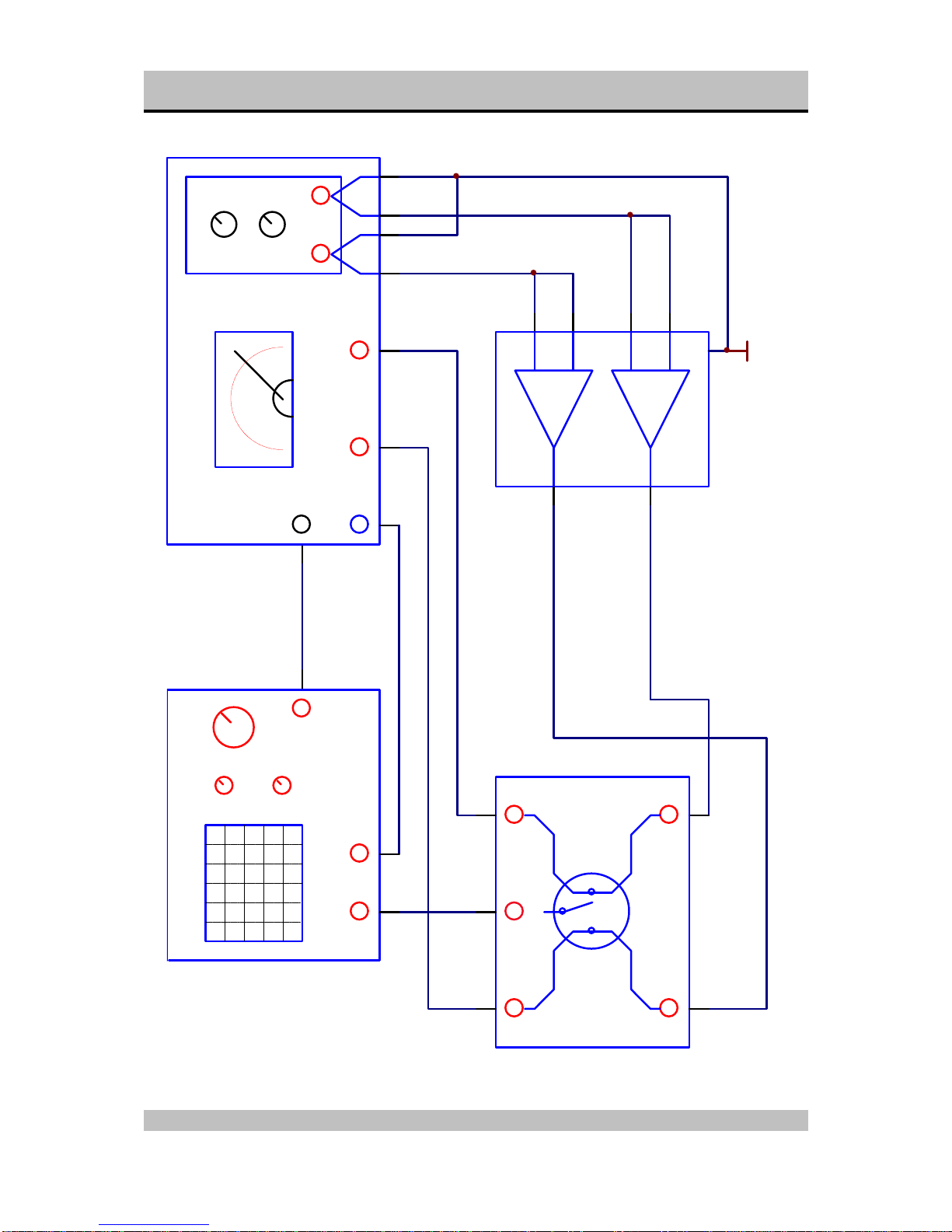
13
Connecting diagram for testing the project 18
Right
Left (+)
(+)
(-)
(-)
Amplfier (30x)
A
B
Project 18
out1 out2
inp2
inp1
gnd
THD Amplitude
Frequency
Oscillator
THD out
(+) (-) (+) (-)
THD ANALYZER
out1 out2
inp2inp1
Scoop
SWITCH-BOX
x
y
inp2
time/div
inp1 gnd
SCOOP
mV mV
GND
SPHINX Project Eighteen Service Manual
14
Connection diagram for common mode adjustment
Right
Left (+)
(+)
(-)
(-)
Amplfier (30x)
A
B
Project 18
out1 out2
inp2
inp1
gnd
THD Amplitude
Frequency
Oscillator
THD out
(+) (-) (+) (-)
THD ANALYZER
out1 out2
inp2inp1
Scoop
SWITCH-BOX
x
y
inp2
time/div
inp1 gnd
SCOOP
GND

SPHINX Project Eighteen Service Manual
15
Schematic layout of all relevant parts
Source resistor
R481
Source resistor
R477
Source resistor
R473
Source resistor
R469
Source resistor
R468
Source resistor
R472
Source resistor
R476
Source resistor
R480
Source resistor
R277
Source resistor
R273
Source resistor
R269
Source resistor
R268
Source resistor
R272
Source resistor
R276
Source resistor
R280
Left Amplifier Right Amplifier
Potmeter P402
HIGH LOW
Potmeter P403
BIAS
PotmeterP404
Offset
PotmeterP401
symmetry
COOLING RIB COOLING RIB
COOLING RIB COOLING RIB
COOLING RIBCOOLING RIB
COOLING RIBCOOLING RIB
Source resistor
R281
PotmeterP201
symmetry
PotmeterP204
Offset
Potmeter P203
LOW HIGH
Potmeter P202
BIAS
Capacitor Array Capacitor Array
Fuse
Fuse
Fuse
Fuse
Power Transformer
LD102
Power Transformer

SPHINX Project Eighteen Service Manual
16
Schematic overview of the Project 18 mainboard
project 18 logic
+60V POWER-RAIL-R
GROUND
-60VPOWER-RAIL-R
project 18 right
+60V POWER-RAIL-R
GROUND
-60VPOWER-RAIL-R
+60V POWER-RAIL-L
GROUND
-60VPOWER-RAIL-L
project 18 left
+60V POWER-RAIL-L
GROUND
-60VPOWER-RAIL-L
+C223 +C224 +C225 +C226 +C227 +C228 +C229 +C230 +C231 +C232 +C233 +C235 +C236
+C452
+C222
+C238 +C239 +C240 +C241 +C242 +C243 +C244 +C245 +C246 +C247 +C248 +C249 +C250 +C252
+C450
+C438
+C423 +C424 +C425 +C426 +C427 +C428 +C429 +C430 +C431 +C432
+C234
+C251
+C436
+C435
+C422
+C439 +C440 +C441 +C442 +C443 +C444 +C445 +C446 +C447 +C448
+C433
+C449
+C434
+C451
C237
U68
C253
U68
C437
U68
C453
U68
F203
20A
F204
20A
F403
20A
F404
20A
+60V POWER-RAIL-R
GROUND
-60VPOWER-RAIL-R
+60V POWER-RAIL-L
-60VPOWER-RAIL-L
CN215
CN217
CN218
CN415
CN417
CN418
POWER-RAIL LEFT CHANNEL
POWER-RAIL RIGHT CHANNEL
60 x 2200U/63V
+60V POWER-RAIL-R
GND
-60VPOWER-RAIL-R
+60V POWER-RAIL-L
GND
-60VPOWER-RAIL-L
+60V POWER-RAIL-R
GND
-60VPOWER-RAIL-R
+60V POWER-RAIL-L
-60VPOWER-RAIL-L
GND

SPHINX Project Eighteen Service Manual
17
Project 18 logic
C104
100N
C105
100N
+
C107
C50V/22U
+
C106
C50V/22U
1
2
3
4
CN104
+12V
-12V
RIGHT DC DETECT
LEFT DC DETECT
R291
100K
R292
10K
R293
100K
R294
1M
R297
10K
R295
10K
R296
10K
R491
100K R492
10K
R493
100K
R494
1M
R495
10K R497
10K
R496
10K
C264
1U
C464
1U
C265
1U
C465
1U
+12V
-12V
D207
D208
D407
D408
+12V
-12VGND
+
C266
C25V/47U
+
C267
C25V/47U
+
C466
C25V/47U
+
C467
C25V/47U
C268
U22
C468
U22
T101
BC547
T103
BC517
T105
BC547
T104
BC547
T110
BC547
T106
BC517
T109
BC517
T107
BC547
T102
BC557
T108
BC557R112
100K
R111
100K
R113
33K2
R110
100K
R108
3K3 R109
3K32
R118
221
R114
10K
R120
2K2
R122
10K
R117
47K5
R115
47K5 R116
10K R121
10K
R119
4K75
LD102
D209 D409 D210 D211 D410 D411
REL203A REL403A
Z103
12V
Z104
12V
Z102
12V
+C109
C16V/1U
+C111
C63V/47U
+C110
C63V/47U
REL201A REL202A REL402AREL401A
OPT0102
OPTIN
OPT0101
OPTOUT
C112
1N
RGLD101
bias & input mute relaysoutput mute relays
frontled greenfrontled red
( stand by ) ( amp on )
+C108
C25V/100U
+12V
+12V
-12V
led error
STB
3
21
84
IC201A
5
67
IC201B
3
21
8 4
IC401A
5
67
IC401B
Vout 3
Vin
1
GND
2
IC101
7812
Vin
2
GND 1
Vout 3
IC102
7912

SPHINX Project Eighteen Service Manual
18
Project 18 supply & relay control schematic
B101
R106
1R0
R107
1R0
R103
1R0
R104
1R0
R105
22K1
CN211
CN214
+C102
C35V/1000U
+C103
C35V/1000U
1
2
3
4
CN103
CN212
CN213
D100
1N4006 +C100
C50V/330U
T100
BDX44
+C101
C50V/10U
Z101
24V
D101
1N4006
REL101
CN102
CN410
CN210
R101
33R
R102
33R
CN411
CN414
CN101
CN201 CN205
CN206
CN207
CN202 CN203
CN204
CN208
CN209
CN401 CN402
CN403
CN404
CN405
CN406
CN407
CN408
CN409
CN412
CN413

SPHINX Project Eighteen Service Manual
19
Project 18 blockdiagram left
+60V POWER-RAIL-L
+70V STAB-RAIL-L
-60V POWER-RAIL-L
-70V STAB-RAIL-L
OUTPUT RELAIS LEFTINPUT L +
INPUT L -
+60V POWER-RAIL-L
+70V STAB-RAIL-L
-60V POWER-RAIL-L
-70V STAB-RAIL-L
OUTPUT RELAIS LEFTINPUT L +
INPUT L -
+70V STAB-RAIL-L
+60V POWER-RAIL-L
-60V POWER-RAIL-L
-70V STAB-RAIL-L
C401
330P
R405
4K75
R402
316
R498
18K2
R404
18K2
R407
604
R403
604
R406
604
R401
4K75
REL401B
CN421
GND
1
3
2
CN422
GND
P401
100
C400
1N
GND
REL401C
GND
GND
+70V STAB-RAIL-L
GROUND
-70V STAB-RAIL-L
+70V STAB-RAIL-L
GROUND
-70V STAB-RAIL-L
S401
project 18
amp end left
project 18
powersupply
left channel
+70V STAB-RAIL-L
GND
-70V STAB-RAIL-L

SPHINX Project Eighteen Service Manual
20
Project 18 blockdiagram right
+60V POWER-RAIL-R
+70V STAB-RAIL-R
-60V POWER-RAIL-R
-70V STAB-RAIL-R
OUTPUT RELAIS RIGHTINPUT R +
INPUT R -
GROUND
+60V POWER-RAIL-R
+70V STAB-RAIL-R
-60V POWER-RAIL-R
-70V STAB-RAIL-R
OUTPUT RELAIS RIGHTINPUT R +
INPUT R -
GROUND
+70V STAB-RAIL-R
+60V POWER-RAIL-R
-60V POWER-RAIL-R
-70V STAB-RAIL-R
C201
330P
R205
4K75
R202
316
R298
18K2
R204
18K2
R207
604
R203
604
R206
604
R201
4K75
REL201B
CN221
GND
1
3
2
CN222
GND
P201
100
C200
1N
GND
REL201C
GND
GND
+70V STAB-RAIL-R
GROUND
-70V STAB-RAIL-R
+70V STAB-RAIL-R
GROUND
-70V STAB-RAIL-R
S201
project 18
powersupply
right channel
project 18
amp end right
GND
GROUND
-70V STAB-RAIL-R
+70V STAB-RAIL-R
Other manuals for PROJECT EIGHTEEN
1
Table of contents
Other SPHINX Amplifier manuals

SPHINX
SPHINX Project Two Mk2 User manual

SPHINX
SPHINX MYTH 5 User manual

SPHINX
SPHINX Myth5 User manual

SPHINX
SPHINX Myth11 User manual

SPHINX
SPHINX Myth 1 User manual

SPHINX
SPHINX PROJECT TEN User manual

SPHINX
SPHINX Myth3 User manual

SPHINX
SPHINX MYTH 11 User manual

SPHINX
SPHINX Project10 User manual

SPHINX
SPHINX PROJECT EIGHTEEN User manual


