SPIDER SAC8 User manual

SAC8 User’s Guide
8Ch Car Driving Recorder

Contents
Preface ∙∙∙∙∙∙∙∙∙∙∙∙∙∙∙∙∙∙∙∙∙∙∙∙∙∙∙∙∙∙∙∙∙ 2
Safety Advice ∙∙∙∙∙∙∙∙∙∙∙∙∙∙∙∙∙∙∙∙∙∙∙∙∙∙∙ 3
Contents ∙∙∙∙∙∙∙∙∙∙∙∙∙∙∙∙∙∙∙∙∙∙∙∙∙∙∙∙∙∙∙ 5
1. Introduction
1-1. SAC8 Overview ∙∙∙∙∙∙∙∙∙∙∙∙∙∙∙∙∙∙∙ 6
1-2. Rear ∙∙∙∙∙∙∙∙∙∙∙∙∙∙∙∙∙∙∙∙∙∙∙∙∙∙∙∙∙∙∙ 7
1-3. Remote controller ∙∙∙∙∙∙∙∙∙∙∙∙∙∙∙∙∙∙ 8
A/V output pin
2. Live Monitoring
2-1. Live Display ∙∙∙∙∙∙∙∙∙∙∙∙∙∙∙∙∙∙∙∙∙∙∙∙ 9
2-2. Menu ∙∙∙∙∙∙∙∙∙∙∙∙∙∙∙∙∙∙∙∙∙∙∙∙∙∙∙∙∙∙∙ 10
3. System Setup
3-1. Virtual Keyboard ∙∙∙∙∙∙∙∙∙∙∙∙∙∙∙∙∙∙∙ 11
3-2. Input the password ∙∙∙∙∙∙∙∙∙∙∙∙∙∙∙∙ 12
3-3. Device
3-3-1. Camera Setup ∙∙∙∙∙∙∙∙∙∙∙∙∙∙∙∙∙∙ 13
3-3-2. Sensor input ∙∙∙∙∙∙∙∙∙∙∙∙∙∙∙∙∙∙∙∙ 14
3-3-3. Video image setup ∙∙∙∙∙∙∙∙∙∙∙∙∙ 15
3-4. Recording
3-4-1. Recording Setup ∙∙∙∙∙∙∙∙∙∙∙∙∙∙∙∙ 16
3-4-2. Recording mode ∙∙∙∙∙∙∙∙∙∙∙∙∙∙∙∙ 17
3-5. Event
3-5-1. Motion detection setup ∙∙∙∙∙∙∙∙ 18
3-5-2. Event setup ∙∙∙∙∙∙∙∙∙∙∙∙∙∙∙∙∙∙∙∙∙ 19
3-6. Additional feature
3-6-1. G sensor setup ∙∙∙∙∙∙∙∙∙∙∙∙∙∙∙∙∙ 20
3-6-2. Setup for rear guide ∙∙∙∙∙∙∙∙∙∙∙∙ 20
3-7. System Setup
3-7-1. Language ∙∙∙∙∙∙∙∙∙∙∙∙∙∙∙∙∙∙∙∙∙∙∙ 21
3-7-2. Time setup ∙∙∙∙∙∙∙∙∙∙∙∙∙∙∙∙∙∙∙∙∙∙ 21
3-7-3. Password setup ∙∙∙∙∙∙∙∙∙∙∙∙∙∙∙∙∙∙∙∙∙∙∙∙ 22
3-7-4. Parking mode setup ∙∙∙∙∙∙∙∙∙∙∙∙∙∙∙∙∙∙∙∙ 23
3-7-5. Signal type ∙∙∙∙∙∙∙∙∙∙∙∙∙∙∙∙∙∙∙∙∙∙∙∙∙∙∙∙∙∙ 24
3-7-6. Audio recording setup ∙∙∙∙∙∙∙∙∙∙∙∙∙∙∙∙∙∙ 24
3-7-7. Disk management ∙∙∙∙∙∙∙∙∙∙∙∙∙∙∙∙∙∙∙∙∙∙ 25
3-7-8. Set up for vehicle information ∙∙∙∙∙∙∙∙∙∙ 25
4. Playback
4-1. Playback ∙∙∙∙∙∙∙∙∙∙∙∙∙∙∙∙∙∙∙∙∙∙∙∙∙∙∙∙∙∙∙∙∙∙ 26
4-2. Set the year, month, date to playback ∙∙ 27
4-3. Time scroll bar ∙∙∙∙∙∙∙∙∙∙∙∙∙∙∙∙∙∙∙∙∙∙∙∙∙∙∙∙ 27
4-4. Playback Control ∙∙∙∙∙∙∙∙∙∙∙∙∙∙∙∙∙∙∙∙∙∙∙∙∙ 28
4-5. Split mode setup ∙∙∙∙∙∙∙∙∙∙∙∙∙∙∙∙∙∙∙∙∙∙∙∙∙∙ 29
5. Backup
5-1. Backup ∙∙∙∙∙∙∙∙∙∙∙∙∙∙∙∙∙∙∙∙∙∙∙∙∙∙∙∙∙∙∙∙∙∙ 30
6. Viewer
6-1. Installation for viewer
/Playback the image ∙∙∙∙∙∙∙∙∙∙∙∙∙∙∙∙∙∙∙∙∙∙ 31
6-2. Configuration of the viewer (1) ∙∙∙∙∙∙∙∙∙∙∙ 35
6-3. Normal recording playback
6-3-1. Select the playback date and time ∙∙ 38
6-3-2. Time scroll bar ∙∙∙∙∙∙∙∙∙∙∙∙∙∙∙∙∙∙∙∙∙∙∙ 38
6-3-3. Time scroll bar usage ∙∙∙∙∙∙∙∙∙∙∙∙∙∙∙∙∙ 39
6-4. Event search ∙∙∙∙∙∙∙∙∙∙∙∙∙∙∙∙∙∙∙∙∙∙∙∙∙∙∙∙∙∙ 40
6-5. Capture ∙∙∙∙∙∙∙∙∙∙∙∙∙∙∙∙∙∙∙∙∙∙∙∙∙∙∙∙∙∙∙∙∙∙∙ 41
6-6. Print the image ∙∙∙∙∙∙∙∙∙∙∙∙∙∙∙∙∙∙∙∙∙∙∙∙∙∙∙ 41
6-7. Backup ∙∙∙∙∙∙∙∙∙∙∙∙∙∙∙∙∙∙∙∙∙∙∙∙∙∙∙∙∙∙∙∙∙∙∙ 42
6-8. Viewer setup ∙∙∙∙∙∙∙∙∙∙∙∙∙∙∙∙∙∙∙∙∙∙∙∙∙∙∙∙∙∙ 43
6-9. DVR setup ∙∙∙∙∙∙∙∙∙∙∙∙∙∙∙∙∙∙∙∙∙∙∙∙∙∙∙∙∙∙∙∙ 44
7. Appendix
7-1. Specifications∙∙∙∙∙∙∙∙∙∙∙∙∙∙∙∙∙∙∙∙∙∙∙∙∙∙∙∙∙ 45
7-2. Dimensions ∙∙∙∙∙∙∙∙∙∙∙∙∙∙∙∙∙∙∙∙∙∙∙∙∙∙∙∙∙ 46
1

Preface
2
Notice
Any unauthorized use of this guide or its contents is prohibited.
The contents may be changed without notice.
The contents of this user guide are comprehensively designed to provide adequate information to
set up and operate the purchased device. Please contact DIS if you have any questions or find any
omissions.
If you find any missing pages in this users guide, please contact your dealer or DIS for a
replacement.
The images and display captures are examples to help you understand this device and may differ
from what you may observe.
Limitation of use
This device is designed and manufactured for commercial use only and is not intended for use
where the failure of the device could lead to death, personal injury, or severe environmental
damage. Please use discretion when using in situations that require high precision or that may
endanger life or damage valuable assets. DIS does not take any responsibility for accidents in such
cases.
Software License Agreement
D-TEG and its suppliers grant to the customer a nonexclusive and nontransferable license to use
the PC Viewer software in object code form solely on a single central processing unit owned or
leased by Customer or otherwise embedded in equipment provided by DIS.
Customer may make one archival copy of the Software provided Customer affixes to such copy all
copyright, confidentiality, and proprietary notices that appear on the original.
Except as expressly authorized above, the customer shall not: copy, in whole or in part, software or
documentation; modify the software; reverse compile or reverse assemble all of any portion of the
software; or rent, lease, distribute, sell, or create derivative works of the software.
Export Restrictions
D-TEG products are controlled under the Korean Export Regulations, please check all relevant laws
and codes and make sure all compliances are met before exporting.
Copyright
The use of recorded data without the expressed authorization of the owner is prohibited.
Trademark
• Microsoft, Windows Vista, Windows7 are trademarks of Microsoft Corporation, registered in the
US and other countries.
• Pentium is a trademark of Intel Corporation, registered in the US and other countries.
• Other company and product names mentioned herein may be trademarks of their respective
companies.
Safety Advice
3
Safety Advice
CAUTION: TO REDUCE THE RISK OF ELECTRIC SHOCK,
DO NOT REMOVE COVER.
NO USER-SERVICEABLE PARTS INSIDE.
REFER SERVICING TO QUALIFIED SERVICE PERSONNEL.
CAUTION
RISK OF ELECTRIC SHOCK
DO NOT OPEN
Please make sure you follow the safety advice/instructions given in the user guide.
CAUTION
RISK OF EXPLOSION IF BATTERY IS REPLACED BY AN INCORRECT TYPE.
DISPOSE OF USED BATTERIES ACCORDING TO THE INSTRUCTIONS.
Battery for RTC (Real Time Clock) inside.
CAUTION
Connect your vehicle’s power cable to the product after starting the vehicle.
The instant over voltage generated when starting up the vehicle may damage
the product if it is already connected.
CAUTION
Damages due to production malfunction, loss of data, or other damages occurring while using
this product shall not be the responsibility of the manufacturer. Although the product is a
device used for recording videos, the product may not save all videos in the case of a
malfunction. In the case of an accident, the sensor may not recognize the shock when the
impact is light and as a result, it may not begin recording automatically.
CAUTION
Install the product where it does not block driver’s visibility and where there is
no airbag installed. This could cause an accident or might injure the passengers in
case of accident.
WARNING:
TO PREVENT FIRE OR ELECTRIC SHOCK HAZARD,
DO NOT EXPOSE THIS APPLIANCE TO RAIN OR MOISTURE.

Safety Advice
4
GPS Reception
It may take between five and thirty minutes to get GPS reception.
1. Activate the product in an area without large buildings to improve
GPS reception.
The commercial purpose GPS has the average range error of more than 15
meters and the range error could be more than 100 meters due to
environmental conditions like buildings, roadside trees etc.
2. The temperature range for optimum operation of the GPS receiver in
your car is -10 ~ 50°C.
3. When using the product for the first time or after a long period (more
than three days), it may take a little longer to recognize your current
location.
It may take between five and thirty minutes to get GPS reception.
1. If there is an object at the end of the GPS antenna
2. If your vehicle has metallic elements on the windshields
3. If equipment generating electromagnetic waves that interfere with the GPS
signal is installed in the vehicle, e.g. other GPS devices such as certain types of
wireless activated alarms, MP3, CD players, etc. using GPS.
4. If you are using a receiver connected by cable, electric interference can be
avoided by simply changing the location of the GPS receiver (antenna).
5. On heavily overcast or cloudy days, if the vehicle is in a covered location
such as under a bridge or raised roadway, in a tunnel, an underground
roadway or parking area, inside a building or surrounded by high-rise
buildings.
6. If GPS signal reception is poor, it may take longer to locate your current
position when the vehicle is moving than when it is stationary.
Situations where reception may be obstructed.
Make sure that the power is turned OFF when attaching or removing HDD,SSD or CF
memory. When a power failure occurs during recording, the recording data may be
earased.

Contents
The Components may be changed without notice.
※The pictures in this manual may differ from the actual product.
※The user manual in order to improve product performance, and are subject
to change without notice to users
Blackbox Remote control
A/V out
Cameras
Power cable
GPS Antenna
Remote control Receiver
Digital IO Cable
HDD Knob
Normal Components
Options Components
5

1
2 3 4 5 7
6
1. Introduction
※The images and display captures are examples to help you understand this
device and may differ from what you may observe.
※The contents may be changed without notice.
1 Power Switch Power On/Off
2 Reset Button Reset as factory default
3 USB 2.0 Upgrade or backup for USB memory
4 Audio Output port Playback audio
5 LED indicators Indicate the device ‘s status with LED
6 SSD/HDD slot Removable 2.5” SSD/HDD slot
7 CF memory card slot Removable CF memory card slot
8 Cover Lock Cover key Lock
9 LED window Monitor LED status
1-1. SAC8 Overview
Door Open
Inside of door
Front view
6
8
9

1. Introduction
GND
GND
VCC
VI
TX
GND
RX
VCC
GND
GND
VCC
ACC
GPS
VI (Video)
Power
GPS
CH1 CH2 CH3 CH4 CH5 CH6 CH7 CH8
IrDa
(RS232)Rx Gnd CC Gnd S5 S3 S1
S6 S4 S2
Tx Gnd C2
C1
S1~S6 : ARM In
C1(12V): ARM Out
C2(Relay): ARM Out
Mic A/V Out Power
Video Input : Use the car signal cable bundle for this connection. Connect the
appropriate car signals to the labeled cables.
Remote contoller receiver : Receive the signal to execute the external remote
controller.
GPS Port : Connect external GPS.
Ethernet connector: Supports network connection.
Sensor in/output & Serial port: Support 6ea of sensor input(S1~S6), 2ea of sensor
output(C1~C2) and RS232(Rx,Tx).
MIC : Connect the external microphone to record audio.
A/V out : Connect the monitor to monitor video or playback.
Power Connector : Use the included power cable bundle for this connection.
Micro USB : Connect the external usb device.
8
1 2
3 4 5 76
9
1
2
3
4
5
6
7
8
9
Rear Diagram
Rear
1-2. Rear
7

•▲▼◀▶ (arrows) : Used when the focus is moved.
•OK : When you choose to enter into a sub-menu or control.
•MENU :Menu screen will pop-up.
It is also used to move to the upper menu.
•VIEW : Change the split image screen.
•Number : Video channels can be selected.
Channel selection in the search screen.
•PWR : Output to an external monitor On / Off
•EMER(Emergency recording) : start recording in situations that
require urgent recording
※To use the remote control, the remote control receiver is required.
A/V output cable
Remote controller
VIDEO: RCA (Yellow)
AUDIO: RCA (White)
GND
VIDEO
AUDIO
1. Introduction
1-3. Remote controller, A/V output pin
8

From the live display, user can monitor as various division and full screen display.
Enter the search & setup menu.
Orange
Continuous Rec
Blue
Motion Rec
Dark Green
Sensor Rec
Yellow
Previous Rec
Purple
Impact Rec
Green
Instant Rec
Gray
Video Loss
1
2
3
4
5
6
7
8
2
1
5 63 4 7 8
3. Live Monitoring
3-1. Live Display
9
Audio Record : Indicate the audio recording status.
Backup : Indicate the backup status.
GPS : Indicate the GPS reception status.
USB : Indicate the status of USB memory.
Speed signal : Indicate the vehicle’s speed.
Camera Name : Indicate the camera’s name.
Date & Time : Indicate the date and time.
Recording Icon : Indicate the recording status as icon

Access the menu from live window.
Screen layout split : Show channels into 1, 4, 9 split s.
Playback : Enter the playback window.
Backup : Enter the backup window.
Setup : Enter the system setup window after input the password.
< Password Input >
Using remote controller’s numeric button or virtual keyboard, input the password.
The password can be changed by going to [Setup -> SYSTEM -> PASSWORD].
421 3
1
2
3
4
3. Live Monitoring
3-2. Menu
10
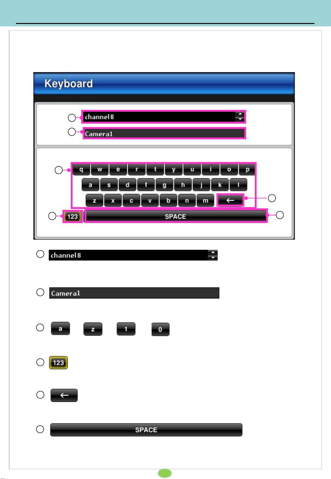
Using virtual keyboard, enable to input alphabet and numbers.
3
Using the remote control’s ‘enter’ key, input “a~z”
Enable to change the camera name.
1
The name change of the camera (default Camera 1~ 8)
2
4
Space key
5
Enable to change the alphabet and number key
6
Delete key
4. System Setup
4-1. Virtual Keyboard
11
1
2
3
4
5
6

Input the password to login the system.
1 Password
Only if the password set up, password window will be appeared.
Using virtual keyboard, password can be typed.
Click ‘Ok’ to enter the next step.
4. System Setup
4-2. Input the password
12
1
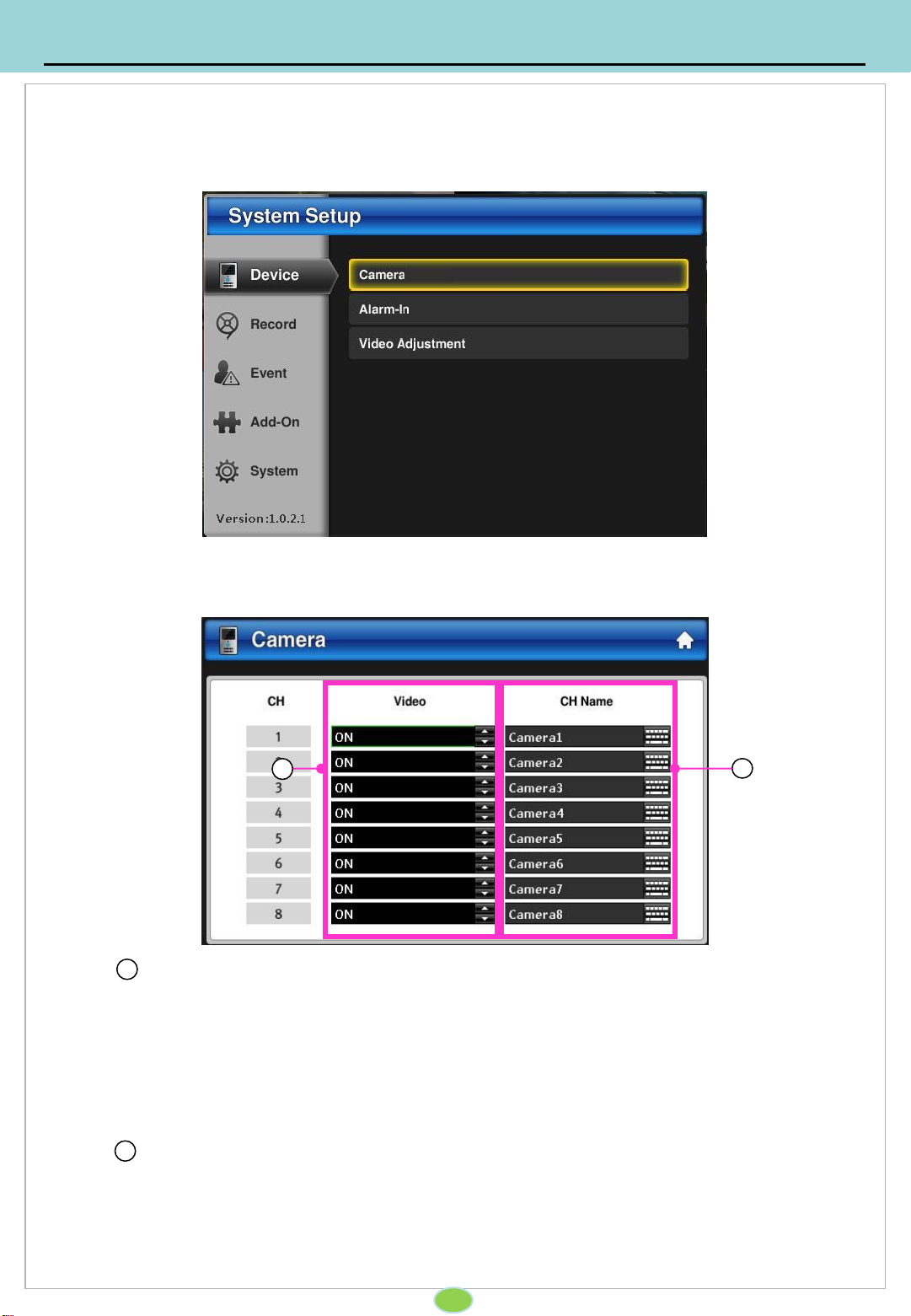
Set up for enabling/disabling the camera and camera’s name.
1 Enable the camera
set up for enabling/disabling cameras.
ON : Enable the camera.
OFF : Disabling the camera.
2 Camera Name
Change the camera title.
Using virtual keyboard, set up the camera title.
4. System Setup
4-3. Device
4-3-1. Camera Setup
13
2
1
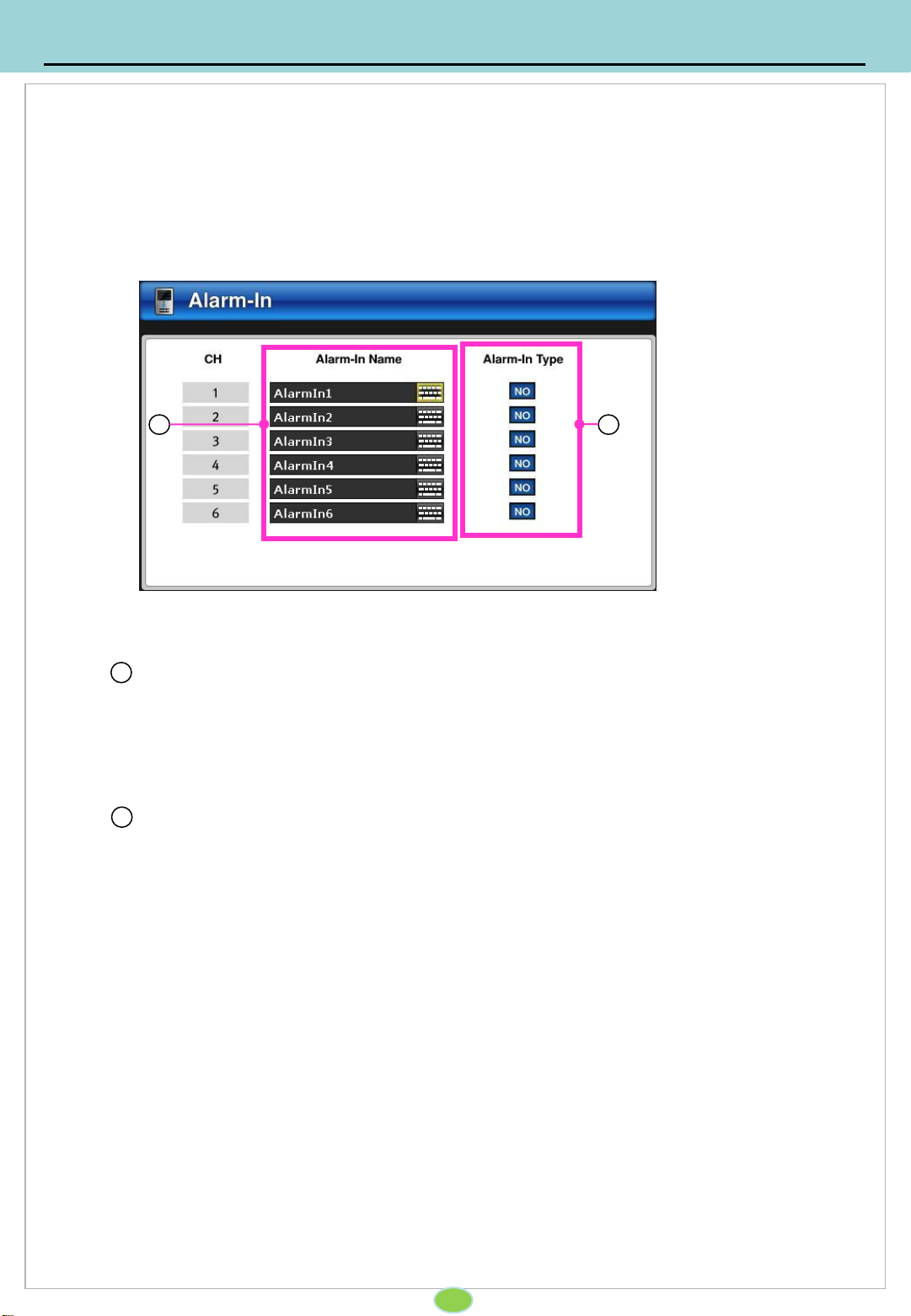
Setup for sensor. Max 6ea of sensor can be set up.
1 Sensor Name
Set up for sensor name using virtual keyboard.
2 Sensor type
Normal Open : Alarm can be triggered when the signal becomes CLOSED.
Normal Close : Alarm is triggered when the signal becomes OPEN.
4. System Setup
14
4-3. Device
4-3-2. Sensor input
21

Cameras’ brightness, saturation, Contrast and tone.
1 Video Adjustment
Each camera’s display can be set up indivisualy.
Brightness : Set up the brightness. ( -20 ~ 20 )
Saturation : Set up the saturation. ( -20 ~ 20 )
Contrast : Set up the contrast. ( -20 ~ 20 )
Tone: Setup the tone. (-20 ~ 20 )
2 Default
Reset to default
3 Apply to All
Apply the current set up parameter to all the other channels.
4. System Setup
15
4-3. Device
4-3-3. Video image setup
21 3

Set up for resolution, frame and video quality.
1 Channel
Indicate the camera’s channel number.
Normal Frame
Set up for normal recording.
NTSC : 1 ~ 30 (For 8ch, 120fps can be recorded in total.)
PAL : 1 ~ 28 (For 8ch, 100fps can be recorded in total.)
Event Frame
Set up for event recoding.
NTSC : 1 ~ 30 (For 8ch, 120fps can be recorded in total.)
PAL : 1 ~ 28 (For 8ch, 100fps can be recorded in total.)
Recording Quality
Set up for recording quality as highest , middle and low.
Apply all
From the one of channel set up parameter, apply to other channels.
2
3
4
5
4. System Setup
16
4-4. Recording
4-4-1. Recording Setup
2
1 3 4 5
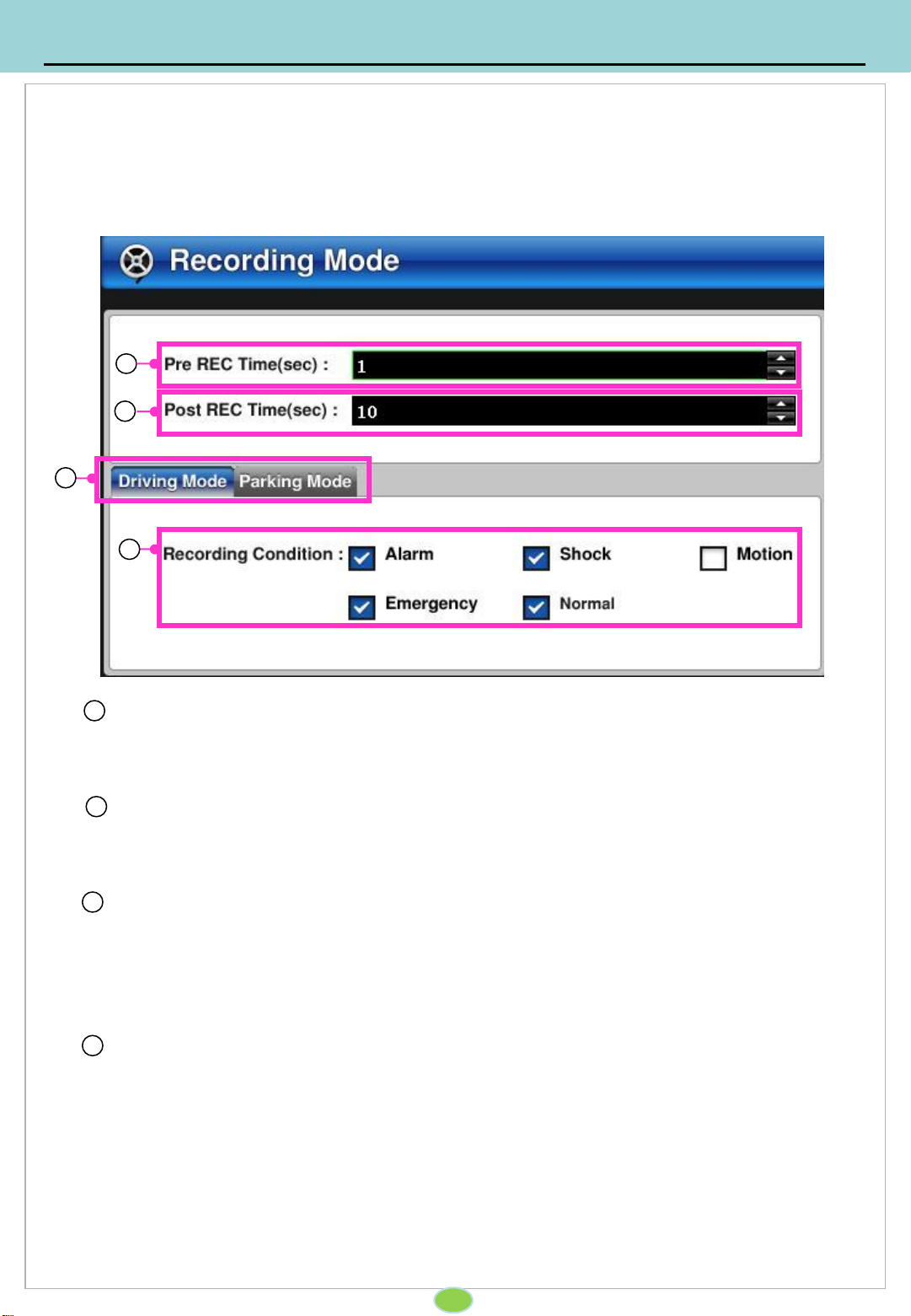
Setup for recording mode.
1 Pre recording
Depending on the set seconds: (1~10sec), for every event there will the set amount of
pre-recorded data.
Post recording
- Depending on the set seconds: “ 3~ 60 “, for every event there will the set amount of
post-recorded data.
2
Driving mode / Parking mode
Driving mode : event recording set up while driving.
Parking mode : event recording set up while parking.
3
Recording Condition
Alarm recording : Setup for sensor recording.
Impact recording : Setup for impact recording.
Motion recording : Setup for motion recording.
Emergency recording: Setup for emergency recording.
Normal recording : Setup for normal recording.
4
4. System Setup
4-4. Recording
4-4-2. Recording mode
17
1
2
3
4

Setup for motion detection. Camera’s sensitivity and usage can be set up.
1
2
Enabling motion detection.
Enable/Disable the motion detection.
motion detection recording the sensor output is are linked with the event.
Sensitivity
Set up for sensiity of motion detection. ( 1 ~ 3 )
3 is most sensitive.
4. System Setup
4-5. Event
4-5-1. Motion detection setup
18
1 2

1 Sensor, Motion detection, Impact
Sensor: With sensor, enabling sensor output 1, output 2 or recording
Motion detection : with motion detected, enabling sensor output 1, output 2 or
recording
Impact detection : with impact detected, enabling sensor output 1, output 2 or
recording.
Set up how DVR operates with sensor, motion detection and impact.
4. System setup
4-5. Event
4-5-2. Event setup
19
1
Table of contents


