Spin Twin-Spin 17 User manual

18 - FORM NO. 041332 / TWIN SPIN 17/20
FLOOR MACHINE
MANUFACTURING
Box 47174
Minneapolis, MN 55447
612/475-9 96 - Phone
612/475-9721 - Fax
OPERATOR MANUAL/PARTS LIST - MODELS 201400, 201300
THIS MANUAL IS FOR MACHINES STARTING WITH SERIAL NUMBER 1126070

20 - FORM NO. 041332 / TWIN SPIN 17/20
TECHNICAL SPECIFICATIONS
Model Twin-Spin 17 Twin-Spin 20
Model Numbe 201400 201300
Moto 1.5 hp, 120V 1.5 hp, 120V
T ansmission Dual-Planeta y Dual-Planeta y
Pad/B ush Speed 190 pm / 300 pm 190 pm / 300 pm
Pad/B ush Size 17” (43 cm) 20” (51 cm)
Wheels 5” (13 cm) 5” (13 cm)
Co d Length 50’ (15 m) 50’ (15 m)
Base Width 18” (46 cm) 20.75” (53 cm)
Height w/Handle 47” (120 cm) 47” (120 cm)
Net Weight (w/pad holde ) 86 lbs (39 kg) 90 lbs (41 kg)
Shipping Weight (w/pad holde ) 90 lbs (41 kg) 94 lbs (43 kg)
Construction:
Handle Tube Ext uded Steel Ext uded Steel
Uppe Handle Injection Molded Nylon Injection Molded Nylon
Base Roto Molded Polyethylene Roto Molded Polyethylene

FORM NO. 041332 / TWIN SPIN 17/20 - 1
TABLE OF CONTENTS
PAGE
INTRODUCTION 2
IMPORTANT SAFETY INSTRUCTIONS 3
IMPORTANTES MESURES DE SÉCURITÉ 4
GROUNDING INSTRUCTIONS 5
MACHINE ASSEMBLY 6
PREPARING THE MACHINE FOR USE 7
OPERATING CONTROLS 8
OPERATION 9
AFTER USE 10
TROUBLESHOOTING 11
HANDLE SYSTEM 12-13
BASE SYSTEM 14-15
WIRING DIAGRAM 15
SOLUTION TANK KIT (OPTIONAL) 16-17

2 - FORM NO. 041332 / TWIN SPIN 17/20
INTRODUCTION
This manual will help you get the most f om you Twin Spin Floor Machine Read it tho oughly befo e ope ating the
machine.
This p oduct is intended fo comme cial use; polishing, sp ay buffing, sc ubbing, st ipping and ota y ca pet shampooing.
PARTS AND SERVICE
Call the DEALER named below fo epai pa ts o se vice. Please specify the Model and Se ial numbe when discussing
you machine.
(Deale , affix se vice sticke he e)
NAME PLATE
The Model Numbe and Se ial Numbe of you machine a e shown on the Nameplate on the back of the moto . This
info mation is often needed when o de ing epai pa ts fo the machine. Use the space below to note the Model Numbe
and Se ial Numbe of you machine fo futu e efe ence.
MODEL NUMBER
SERIAL NUMBER
UNCRATING
When the machine is delive ed, ca efully inspect the shipping ca ton and the machine fo damage. If damage is evident,
save the shipping ca ton so that it can be inspected by the t ucking company that delive ed it. Contact the t ucking company
immediately to file a f eight damage claim.

FORM NO. 041332 / TWIN SPIN 17/20 - 3
IMPORTANT SAFETY INSTRUCTIONS
When using an elect ical appliance, basic p ecautions should always be followed, including the following:
Read all inst uctions befo e using.
WARNING!
To educe isk of fi e, elect ic shock, o inju y:
*Do not leave the appliance when it is plugged in. Unplug the unit f om the outlet when not in use and befo e se vicing.
*To avoid elect ic shock, do not expose to ain. Sto e indoo s.
*Do not allow to be used as a toy. Close attention is necessa y when used by o nea child en.
*Use only as desc ibed in this manual. Use only manufactu e ’s ecommended attachments.
*Do not use with damaged co d o plug. If appliance is not wo king as it should, has been d opped, damaged, left
outdoo s, o d opped into wate , etu n it to a se vice cente .
*Do not pull o ca y by co d, use co d as a handle, close a doo on a co d, o pull co d a ound sha p edges o co ne s.
Do not un appliance ove co d. Keep co d away f om heated su faces.
*Do not unplug by pulling on co d. To unplug, g asp the plug, not the co d.
*Do not handle plug o appliance with wet hands.
*Do not put any object into openings. Do not use with any opening blocked; keep f ee of dust, lint, hai , and anything
that may educe ai flow.
*Keep hai , loose clothing, finge s, and all pa ts of body away f om openings and moving pa ts.
*Tu n off all cont ols befo e unplugging.
*Use ext a ca e when cleaning on stai s.
*Do not use nea flammable o combustible liquids such as gasoline o use in a eas whe e they may be p esent.
*Connect to a p ope ly g ounded outlet only. See G ounding Inst uctions.
SAVE THESE INSTRUCTIONS

4 - FORM NO. 041332 / TWIN SPIN 17/20
IMPORTANTES MESURES DE SÉCURITÉ
L’utilisation d’un appa eil élect ique demande ce taines p écautions:
LIRE TOUTES LES INSTRUCTIONS AVANT DE FAIRE FONCTIONNER (CET APPAREIL)
AVERTISSEMENT:
Pou édui e les isques d’incendie, de choc élect ique ou de blessu e:
*Ne pas laisse l’appa eil sans su veillance lo squ’il est b anché. Déb anche lo sque l’appa eil n’est pas utilisé et avant
l’ent etien.
*Pou édui e les isques de choc élect ique, utilise à l’inté ieu seulement.
*Ne pas pe mett e aux enfants de joue avec l’appa eil. Une attention pa ticuliè e est nécessai e lo sque l’appa eil
est utilisé pa des enfants ou à p oximité de ces de nie s.
*N’utilise que confo mément à cette notice avec les accessoi es ecommandés pa le fab icant.
*Ne pas utilise si le co don ou la fiche est endommagé. Retou ne l’appa eil à un atelie de épa ation s’il ne fonctionne
pas bien, s’il est tombé ou s’il a été endommagé, oublié à l’exté ieu ou imme gé.
*Ne pas ti e souleve ou t aîne l’appa eil pa le co don. Ne pas utilise le co don comme une poignée, le coince dans
l’emb asu e d’une po te ou l’appuye cont e des a êtes vives ou des coins. Ne pas fai e oule l’appa eil su le co don.
Ga de le co don à l’éca t des su faces chaudes.
*Ne pas déb anche en ti ant su le co don. Ti e plutôt la fiche.
*Ne pas touche la fiche ou l’appa eil lo sque vos mains sont humides.
*N’insé e aucun objet dans les ouve tu es. Ne pas utilise l’appa eil lo squ’une ouve tu e est bloquée. S’assu e que
de la poussiè e, de la peluche, des cheveux ou d’aut es matiè es ne éduisent pas le débit d’ai .
*Mainteni les cheveux, les vêtements amples, les doigts et toutes les pa ties du co ps à l’éca t des ouve tu es et des
pièces mobiles.
*Mett e toutes les commandes à la position ARRÊT avant de déb anche l’appa eil.
*Use de p udence lo s du nettoyage des escalie s.
*Ne pas aspi e des liquides inflammables o combustibles, comme de l’essence, et ne pas fai e fonctionne dans des
end oits ou peuvent se t ouve de tels liquides.
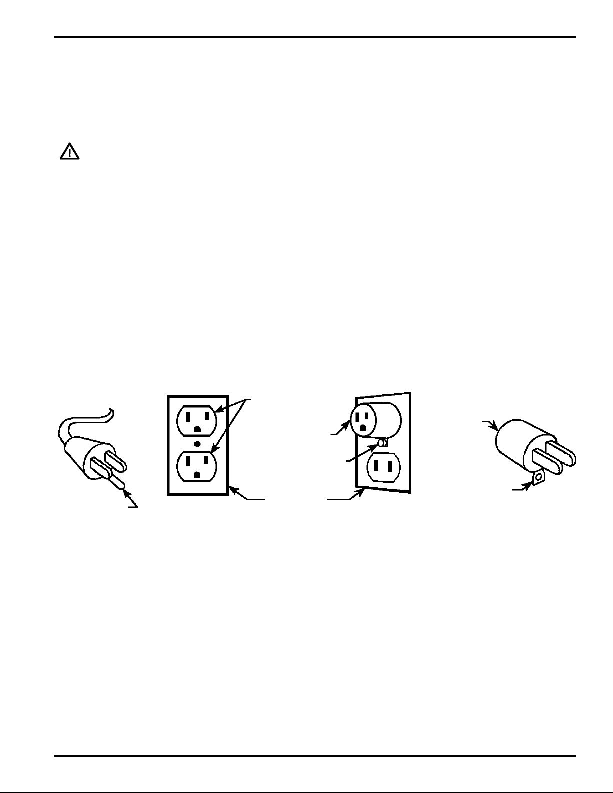
*Ne b anche qu’à une p ise de cou ant avec mise à la te e. Voi les inst uctions visant la mise à la te e.
CONSERVER CES INSTRUCTIONS

FORM NO. 041332 / TWIN SPIN 17/20 - 5
This appliance must be g ounded. If it should elect ically malfunction, g ounding p ovides a path of least esistance fo
elect ic cu ent to educe the isk of elect ic shock. This appliance is equipped with a co d having an equipment-g ounding
conducto and g ounding plug. The plug must be plugged into an app op iate outlet that is p ope ly installed and g ounded
in acco dance with all local codes and o dinances.
DANGER!
Imp ope connection of the equipment-g ounding conducto can esult in a isk of elect ic shock. Check with a qualified
elect ician o se vice pe son if you a e in doubt as to whethe the outlet is p ope ly g ounded. Do not modify the plug p ovided
with the appliance. If it will not fit the outlet, have a p ope outlet installed by a qualified elect ician.
This appliance is fo use on a nominal 120-volt ci cuit, and has a g ounding plug that looks like the plug illust ated in Figu e
1 below. A tempo a y adapte illust ated in Figu es 2 and 3 may be used to connect this plug to a 2-pole eceptacle as shown
in Figu e 2 if a p ope ly g ounded outlet is not available. The tempo a y adapte should be used only until a p ope ly
g ounded outlet (Figu e 1) can be installed by a qualified elect ician. The g een-colo ed igid ea , tab, o the like extending
f om the adapte must be connected to a pe manent g ound such as a p ope ly g ounded outlet box cove . Wheneve the
adapte is used, it must be held in place by a metal sc ew. G ounding adapte s a e not app oved fo use in Canada.
Replace the plug if the g ounding pin is damaged o b oken.
The G een (o G een/Yellow) wi e in the co d is the g ounding wi e. When eplacing a plug, this wi e must be attached to
the g ounding pin only.
Extension co ds connected to this machine should be 12 gauge, th ee-wi e co ds with th ee-p ong plugs and outlets. DO
NOT use extension co ds mo e than 50 feet (15 m) long.
GROUNDING INSTRUCTIONS
FIGURE 1 FIGURE 2 FIGURE 3
GROUNDING PLUG
GROUNDED
OUTLET BOX
THREE-PRONG
GROUNDED OUTLET
ADAPTER
METAL SCREW
ADAPTER
TAB FOR
GROUNDING
SCREW

6 - FORM NO. 041332 / TWIN SPIN 17/20
J
A
B
D
E
F
G
K
L
M
This pa t "H" comes assembled
with the base housing.
Plug these (2) powe co ds togethe .
K
N
Make su e "foot g ip" su face of pa t
"C" is facing up as shown.
MACHINE ASSEMBLY
Handle to base, tools needed; (2) 9/16” open end o combination w enches.
1Unpack the supplied ha dwa e and become familia with the pa t assembly by studying Figu e 1.
2Install the (2) “K” bushings into the base housing suppo t ea s as shown.
FIGURE 1
3Position the Handle Tube “J” between
the “K” Bushings, making su e the powe
co d is on the left side of the machine as
shown. Inse t the Space “N” into the
opening in the bottom of the Handle
Tube “J” and align the space with the
holes in the Handle Tube.
4Attach the handle tube to the base
housing using the long bolt “L” and nut
“M” (hold Space “N” in place so Bolt “L”
goes th ough it).
5Install the handle a m latch “H” to the
handle tube “J” using the supplied ha d-
wa e items “A” - “G” as shown.
6Plug the (2) powe co d ends togethe
as shown.
Items “A” - “G” function togethe as the handle
position lock leve “Kwik Lok”. The “Kwik
Lok” leve is locked by pushing the leve
down and eleased by pulling up. NOTE: To
eliminate any slippage, tighten nut “G”.

FORM NO. 041332 / TWIN SPIN 17/20 - 7
PREPARING THE MACHINE FOR USE
WARNING!
This machine contains moving pa ts. To educe the isk of inju y, always unplug the powe co d befo e se vicing.
INSTALLING THE BRUSH OR PAD HOLDER
Align the lugs with the co esponding slots in the b ush o pad holde and tu n the b ush o pad holde counte clockwise
to lock it in place. To emove b ush/pad holde , give it a quick, ha d tu n clockwise.
Lugs
Slots
CAUTION!
Using the w ong b ush o pad on this machine can damage the floo o ove load the moto .

8 - FORM NO. 041332 / TWIN SPIN 17/20
OPERATING CONTROLS
1 Operator Handle Grips
2 Switch Lever Safety Lock Button
3 Switch Levers - Squeeze - ON / Release - OFF
4 “Kwik Lok” Handle Adjustment Lever
5 Power Cord
6 Operator Handle
7 LO/HI Speed Selector Switch
1
2
3
3
1
6
4
5
7

FORM NO. 041332 / TWIN SPIN 17/20 - 9
OPERATION
1Unw ap the Powe Co d and plug it into a p ope ly g ounded outlet.
2Select the desi ed speed setting; Low-190 pm, High-300 pm.
TWIN SPIN SPEED SELECTOR GUIDE
Cleaning Application Low Speed High Speed
190 rpm 300 rpm
Ca pet Shampooing X
St ipping X
Heavy Sc ubbing X
Bonnett Cleaning X
Light Sc ubbing X X
Ca pet Shampooing (w/Soft-Touch B ush) X X
Sp ay Cleaning / Buffing X
Buffing X
Polishing X
NOTE: Speed should not be changed while in ope ation. To change speed, shut off machine, select desi ed speed
setting and epeat steps 2-5.
3Loosen the foot ope ated “Kwik Lok” leve with the toe of you foot by pulling up on the bottom of the leve . Move the
Ope ato Handle downwa d until you a ms a e almost st aight. Then step down on top of the leve to lock it.
4Lift the Handle until the b ush (o pad) is flat against the floo .
WARNING!
Be p epa ed to cont ol the machine as soon as the moto sta ts.
Just a slight up o down movement of the Handle will make the machine move f om side to side. Raise the Handle to go
ight. Lowe the Handle to go left.
CAUTION!
Immediately sta t moving the machine back and fo th. Keep the machine moving while the moto is unning to avoid damage
to the floo o ca pet.
5Hold one of the Ope ato Hand G ips fi mly, push the Safety Lock Button and then comp ess the switch leve s to sta t
the moto . NOTE: When the dual cont olled switch leve s a e eleased, the machine shuts off immediately.
NOTE: When sp ay buffing, check the pad eve y 15 minutes fo di t and wax build-up. If the pad is di ty, tu n it ove
to expose the clean side o install a clean pad.

10 - FORM NO. 041332 / TWIN SPIN 17/20
AFTER USE
1Unplug the Powe Co d, coil it and hang it f om the Ope ato Handle G ips.
2Remove the pad holde o b ush f om the machine. Clean the pad o b ush and hang it up to d y. Allow buffing pads
to d y completely befo e using again.
Sto e b ushes and pad holde s sepa ate f om the machine. Neve sto e the machine with the pad holde o b ush on
the machine.
3Wipe the enti e machine with a clean, damp cloth. Wipe the unde side of the b ush housing afte wet use.
4Inspect the enti e machine and all accesso ies fo damage. Pe fo m any equi ed maintenance o epai s befo e
sto age.
5Sto e the machine in a clean, d y place with the Handle locked in the up ight position.

FORM NO. 041332 / TWIN SPIN 17/20 - 11
TROUBLESHOOTING
SWIRLS ON THE FLOOR AFTER SCRUBBING
• Floo not clean.
• Inco ect solution.
• A ea not p ope ly swept - deb is in pad o b ush.
• Imp ope pad o b ush fo the job.
• Moving the machine too fast.
• Inco ect speed selected.
SWIRLS ON THE FLOOR AFTER DRY BUFFING
• Moving the machine too fast.
• Floo finish too soft.
• A ea not p ope ly swept - deb is in pad o b ush.
• Imp ope pad o b ush fo the job.
CIRCLES ON THE FLOOR
• Machine standing still while the b ush o pad is unning.
FLOOR FINISH REMOVED
• Imp ope pad... too agg essive.
• Solution too st ong.
MACHINE WOBBLES DURING OPERATION
• Defective pad... one side is mo e dense than the othe .
• Machine left sitting on b ush o pad fo extended pe iod of time causing b istles o pad to “take a set”.
• Pad not “seated” p ope ly into pad holde b istles.
• Wa ped block on b ush o padholde - eplace.
MACHINE DOES NOT RUN
• Check plug fo p ope connection - on machine and at wall outlet.
• Check building ci cuit b eake .
• Call fo se vice.

12 - FORM NO. 041332 / TWIN SPIN 17/20
1
1
2
3
4
5
25
3
7
8
9
10
11
13
14
14
15
16
17
18
19
20
21
22
23
12
FRONT
24
6

FORM NO. 041332 / TWIN SPIN 17/20 - 13
HANDLE SYSTEM
Item Part No. Qty Description
1 002098 6 Wsh, Flt SAE 1/4
2 002506 1 Scr, Hex Hd 3/8-16 x 5.00
3 002769 2 Nut, Hex Nyl Loc 3/8-16
4 002777 1 Scr, Hex Hd 3/8-16 x 7.00
5 002825 4 Scr, Pan Phil 1/4-20 x 1.25
6 201023 1 Spacer
7 009195 1 Wsh, Flt .40 x 1.25 x .16
8 009196 1 Wsh, Flt Hardened .40 x 1.00 x .16
9 014828 1 Decal, Warning
10 382818 1 Strain Relief
11 201010 1 Handle Tube
12 263648 1 Spring, Plate
13 201015 1 Bracket
14 201016 2 Bushing
15 201025 1 Handle
16 201026 1 Handle Cover
17 201027 2 Handle Lever
18 201028 1 Latch Arm
19 201029 1 Pin
20 201031 1 Button, Lock
21 201032 1 Cord Set 14/3 x 50'
22 201033 1 Cord Assembly 14/3
23 201034 1 Switch, N.O. SPST Snap
24 015852 1 Decal, Spin
25 002292 2 Scr, Pan Phil 1/4-20 x 1.00

14 - FORM NO. 041332 / TWIN SPIN 17/20
FRONT
19
7
14
15
1
16
11
12
5
621
20
3
5
4
4
12
89
5
6
10
17
2
18
13
evised 11/98

FORM NO. 041332 / TWIN SPIN 17/20 - 15
BASE SYSTEM
Item Part No. Qty Description
1 002292 1 Sc , Pan Phil 1/4-20 x 1.00
2 002708 1 Nut, Hex Nyl Loc 1/4-20
3 003318 8 Sc , Hex Hd Loc 1/4-20 x 1.25
4 009001 2 Wsh, Bowed .51 x .90 x .008
5 009002 10 Wsh, Flt .26 x .90 x .06
6 003039 2 Sc , Hex Loc 1/4-20 x .50
7 009209 2 Sc , Pan Phil Thd Fo m 10-24 x 1.00
8 201011 1 A m, Handle Latch
9 201089 1 Axle
10 201014 1 Co d Set
11 201017 1 Base Housing 17"
201012 1 Base Housing 20"
12 201018 2 Wheel 5.00 x 1.50
13 201320 1 Housing, Switch
14 201321 1 Cove , Moto
15 201322 1 Sc een
16 201330 1 Moto Assembly, 2 Speed, 115V
* 201603 2 Sc , Hex Hd Mach 1/4-28 x 7.00
* 201604 1 Bushing/G ommet Rubbe
* 201605 1 Wash B ng Sp ing
* 201606 1 Fan Stamped
* 201607 1 Bea ing
* 201608 1 Compl. Comm Cu Assy 180
* 201609 1 Speed Ct l & Lead Assy
* 201610 1 Com Cove
* 201611 1 Compl. B ush Ring & Lead
* 201612 1 B ush Ring Assy
* 201613 4 B ush Sp ing
* 201614 2 B ush Assy
* 201615 1 Compl. Stat. Assy
* 201616 1 Compl. A m. Asy
* 180163 1 Rectifie , 35A
WIRING DIAGRAM
Item Part No. Qty Description
S1 201034 1 Switch, N.O. SPST Snap
S2 377003 1 Switch, Rocke
M 201330 1 Moto Assembly, 2 Speed
L
N
G
M~
S2
120Vac
BLKL1
WHT
GRN
WHT
S1
BLK
L2
17 377003 1 Switch, Rocke
18 382818 1 St ain Relief
19 015866 1 Decal, Twin Spin 17
* 015867 1 Decal, Twin Spin 20
20 506006 1 Clutch Plate, Unive sal
21 505910 1 Sho t-T im Pad Holde , 17" (optional)
** 505920 1 Sho t-T im Pad Holde , 20"
** 201075 1 Weight Kit 17
** 201062 1 Weight Kit 20
** 505270 1 Level-Set Pad Holde 17
** 505280 1 Level-Set Pad Holde 20
** 505915 1 P oLite™ B ush 17
** 505925 1 P oLite™ B ush 20
** 505914 1 P olene B ush 17
** 505924 1 P olene B ush 20
** 505911 1 MagnaG it™ 46 B ush 17
** 505921 1 MagnaG it™ 46 B ush 20
** 505912 1 DynaG it™ 80 B ush 17
** 505922 1 DynaG it™ 80 B ush 20
** 505918 1 MidLite G it™ 180 B ush 17
** 505928 1 MidLite G it™ 180 B ush 20
** 505917 1 MidG it™ 240 B ush 17
** 505927 1 MidG it™ 240 B ush 20
** 505913 1 AgLite™ 500 B ush 17
** 505923 1 AgLite™ 500 B ush 20
** 505916 1 Union Mix B ush 17
** 505926 1 Union Mix B ush 20
** 505539 1 Soft-Touch™ Shampoo B ush 17
** 505540 1 Soft-Touch™ Shampoo B ush 20
** 506006 A/R Clutch Plate fo Above B ushes
** 393567 A/R "Big Mouth" Pad Retaine
* = Not Shown
** = Optional
Item Part No. Qty Description
NOTE: Pad Holde s and B ushes come complete with Indust y Standa d NP-92 Clutch Plate.
evised 11/98

16 - FORM NO. 041332 / TWIN SPIN 17/20
1
FRONT
1
2
22
2
34
45
5
6
7
8
9
10
11
12
12
13
13
14
15
16

FORM NO. 041332 / TWIN SPIN 17/20 - 17
SOLUTION TANK KIT
Item Part No. Qty Description
201050 1 Solution Tank Kit (includes everything below)
040562 1 Instruction Sheet
201004 1 Solution Tank Assembly (#1-15)
1 001939 4 Wsh, Flt SAE 5/16
2 002826 4 Nut, Hex Nyl Loc-Thin 5/16-18
3 002884 4 Scr, Hex Hd SS 5/16-18 x 1.25
4 009217 2 Nut, Hex Flange Loc 5/16
5 201005 2 Strap
6 201007 1 Plug
7 201008 1 Handle, Valve
8 201020 1 Tank, Solution
9 201035 1 Barb, Adapter 3/8 x 3/4 NPT
10 201036 1 Hose, PVC
11 201047 4 Wsh, Sealing SS 5/16
12 352829 2 Clamp, Hose SAE #52
13 370711 2 Nut, Thumb
14 379170 1 Spring, Compression
15 745550 1 O-Ring
16 201061 1 Washer

FORM NO. 041332 / TWIN SPIN 17/20 - 19
© Printed in U.S.A. 03/96 Form Number 041332
This manual suits for next models
3
Table of contents
Popular Floor Machine manuals by other brands

Numatic
Numatic TTB-1620 Owner's instructions

IGEFA
IGEFA bluematic SD 43 ORBITAL Use and maintenance manual

HAWK ENTERPRISES
HAWK ENTERPRISES HP1513-1500 manual

Husqvarna
Husqvarna BMG 780 Operator's manual

WerkMaster
WerkMaster viper Operation & service manual

Clarke
Clarke C-1800HS Instruction book and parts list