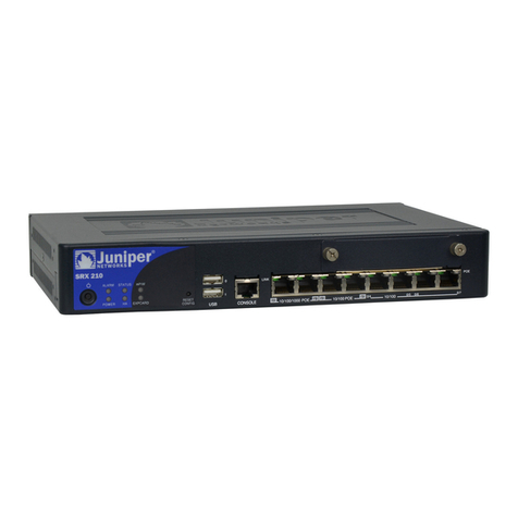
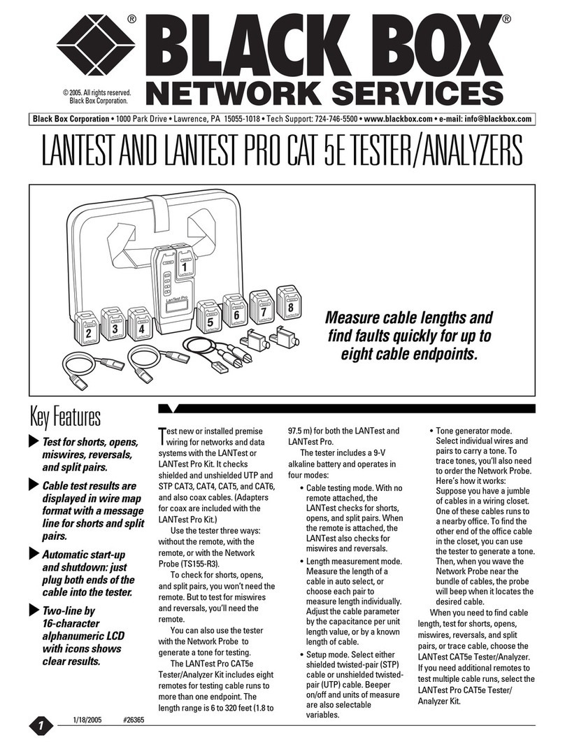
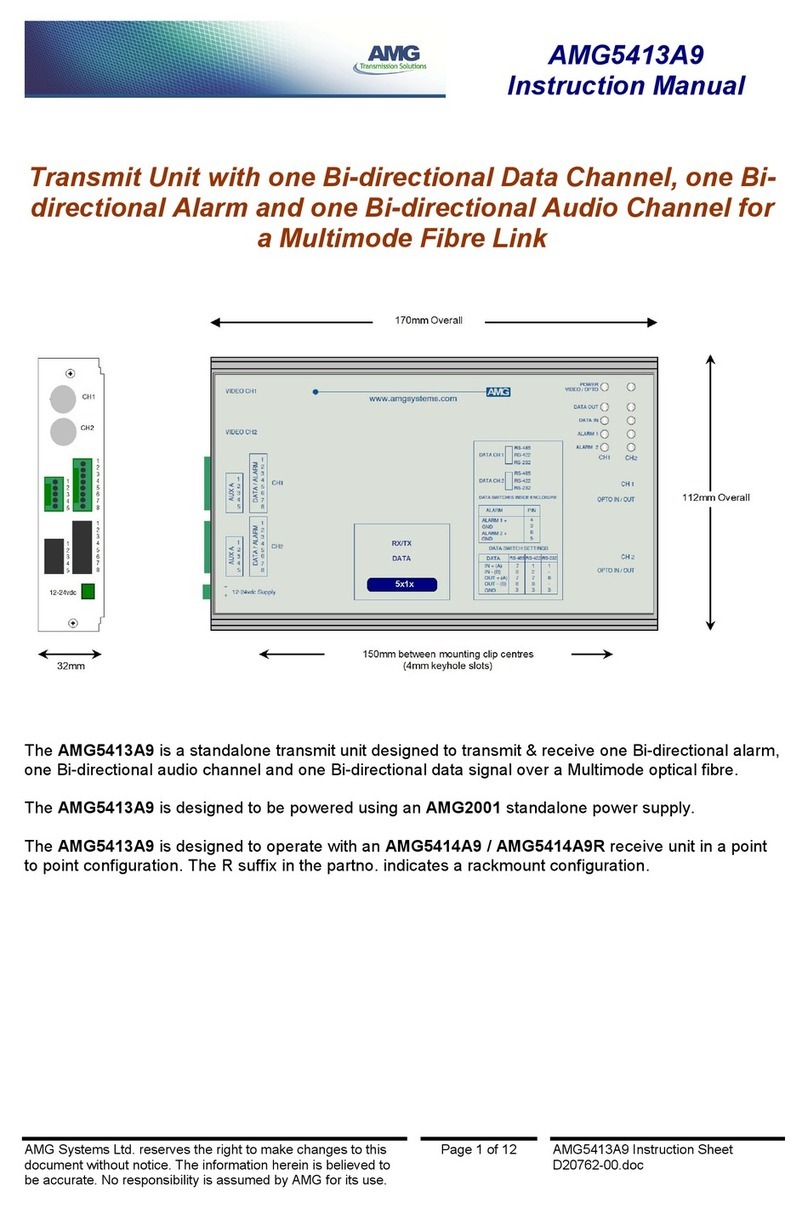
Spirent communications SmartBits 600x User manual

Artisan Technology Group is your source for quality
new and certied-used/pre-owned equipment
• FAST SHIPPING AND
DELIVERY
• TENS OF THOUSANDS OF
IN-STOCK ITEMS
• EQUIPMENT DEMOS
• HUNDREDS OF
MANUFACTURERS
SUPPORTED
• LEASING/MONTHLY
RENTALS
• ITAR CERTIFIED
SECURE ASSET SOLUTIONS
SERVICE CENTER REPAIRS
Experienced engineers and technicians on staff
at our full-service, in-house repair center
WE BUY USED EQUIPMENT
Sell your excess, underutilized, and idle used equipment
We also offer credit for buy-backs and trade-ins
www.artisantg.com/WeBuyEquipment
REMOTE INSPECTION
Remotely inspect equipment before purchasing with
our interactive website at www.instraview.com
LOOKING FOR MORE INFORMATION?
Visit us on the web at www.artisantg.com for more
information on price quotations, drivers, technical
specications, manuals, and documentation
Contact us: (888) 88-SOURCE | sales@artisantg.com | www.artisantg.com
SM
View
Instra

P/N 340-1309-001 REV B
Installation Guide
SmartBits 600x/6000x
October 2004
Artisan Technology Group - Quality Instrumentation ... Guaranteed | (888) 88-SOURCE | www.artisantg.com

Spirent Communications, Inc.
26750 Agoura Road
Calabasas, CA
91302 USA
Support Contacts
E-mail: [email protected]
Web: http://support.spirentcom.com
Toll Free: 1-800-SPIRENT (1-800-774-7368)
Phone: + 1 818-676-2300
Fax: +1 818-880-9154
Copyright
© 2004 Spirent Communications, Inc. All Rights Reserved.
All of the company names and/or brand names and/or product names referred to in this document, in particular, the
name “Spirent” and its logo device, are either registered trademarks or trademarks of Spirent plc and its subsidiaries,
pending registration in accordance with relevant national laws. All other registered trademarks or trademarks are the
property of their respective owners.
The information contained in this document is subject to change without notice and does not represent a commitment
on the part of Spirent Communications. The information in this document is believed to be accurate and reliable,
however, Spirent Communications assumes no responsibility or liability for any errors or inaccuracies that may appear
in the document.
Warranty
Spirent Communications, Inc.(“Spirent”) warrants that its Products will conform to the description on the face of
order, that it will convey good title thereto, and that the Product will be delivered free from any lawful security interest
or other lien or encumbrance.
Spirent further warrants to Customer that hardware which it supplies and the tangible media on which it supplies
software will be free from significant defects in materials and workmanship for a period of twelve (12) months, except
as otherwise noted, from the date of delivery (the “Warranty Period”), under normal use and conditions.
To the extent the Product is or contains software (“Software”), Spirent also warrants that during the Warranty Period,
the Software which it supplies will operate substantially in accordance with the specifications supplied by Spirent for
such Software. Spirent does not warrant that the functions contained in the Software will meet a specific requirement
or that the operation will be uninterrupted or error free. Spirent shall have no warranty obligations whatsoever with
respect to any Software which has been modified in any manner by Customer or any third party. The Warranty Period
for Wireless software products shall be defined as ninety (90) days from the date of delivery.
Defective Products and Software under warranty shall be, at Spirent’s discretion, repaired or replaced or a credit issued
to Customer’s account for an amount equal to the price paid for such Product provided that: (a) such Product is
returned to Spirent after first obtaining a return authorization number and shipping instructions, freight prepaid, to
Spirent’s location in the United States; (b) Customer provides a written explanation of the defect or Software failure
claimed by Customer; and (c) the claimed defect actually exists and was not caused by neglect, accident, misuse,
improper installation, improper repair, fire, flood, lightning, power surges, earthquake, or alteration. Spirent will ship
repaired Products to Customer, freight prepaid, within ten (10) working days after receipt of defective Products.
Except as otherwise stated, any claim on account of defective materials or for any other cause whatsoever will
conclusively be deemed waived by Customer unless written notice thereof is given to Spirent within the Warranty
Period. Spirent reserves the right to change the warranty and service policy set forth above at any time, after reasonable
notice and without liability to Customer.
TO THE EXTENT PERMITTED BY APPLICABLE LAW, ALL IMPLIED WARRANTIES, INCLUDING BUT
NOT LIMITED TO IMPLIED WARRANTIES OF MERCHANTABILITY, NONINFRINGEMENT AND FITNESS
FOR A PARTICULAR PURPOSE, ARE HEREBY EXCLUDED, AND THE LIABILITY OF SPIRENT, IF ANY,
FOR DAMAGE RELATING TO ANY ALLEGEDLY DEFECTIVE PRODUCT SHALL BE LIMITED TO THE
ACTUAL PRICE PAID BY THE CUSTOMER FOR SUCH PRODUCT. THE PROVISIONS SET FORTH ABOVE
STATE SPIRENT’S ENTIRE RESPONSIBILITY AND CUSTOMER’S SOLE AND EXCLUSIVE REMEDY WITH
RESPECT TO ANY BREACH OF ANY WARRANTY.
Artisan Technology Group - Quality Instrumentation ... Guaranteed | (888) 88-SOURCE | www.artisantg.com

SmartBits 600x/6000x Installation Guide |iii
Contents
About This Guide. . . . . . . . . . . . . . . . . . . . . . . . . . . . . . . . . . . . . . . . . . . . . . . . . . . . . . . . . 1
Purpose. . . . . . . . . . . . . . . . . . . . . . . . . . . . . . . . . . . . . . . . . . . . . . . . . . . . . . . . . . . . . . . . . . . . 2
Audience . . . . . . . . . . . . . . . . . . . . . . . . . . . . . . . . . . . . . . . . . . . . . . . . . . . . . . . . . . . . . . . . . . 2
Manual Content . . . . . . . . . . . . . . . . . . . . . . . . . . . . . . . . . . . . . . . . . . . . . . . . . . . . . . . . . . . . . 2
Conventions . . . . . . . . . . . . . . . . . . . . . . . . . . . . . . . . . . . . . . . . . . . . . . . . . . . . . . . . . . . . . . . . 3
Related Manuals. . . . . . . . . . . . . . . . . . . . . . . . . . . . . . . . . . . . . . . . . . . . . . . . . . . . . . . . . . . . . 5
Online Help . . . . . . . . . . . . . . . . . . . . . . . . . . . . . . . . . . . . . . . . . . . . . . . . . . . . . . . . . . . . . . . . 5
SmartBits Hardware Handling/Cleaning Practices . . . . . . . . . . . . . . . . . . . . . . . . . . . . . . . . . . 5
How to Contact Us. . . . . . . . . . . . . . . . . . . . . . . . . . . . . . . . . . . . . . . . . . . . . . . . . . . . . . . . . . . 6
Chapter 1: About SmartBits Chassis . . . . . . . . . . . . . . . . . . . . . . . . . . . . . . . . . . . . . 7
Introduction . . . . . . . . . . . . . . . . . . . . . . . . . . . . . . . . . . . . . . . . . . . . . . . . . . . . . . . . . . . . . . . . 8
SmartBits Overview. . . . . . . . . . . . . . . . . . . . . . . . . . . . . . . . . . . . . . . . . . . . . . . . . . . . . . . . . . 8
SmartBits Chassis Models . . . . . . . . . . . . . . . . . . . . . . . . . . . . . . . . . . . . . . . . . . . . . . . . . . . . . 9
SmartBits 600x/6000x Chassis Features . . . . . . . . . . . . . . . . . . . . . . . . . . . . . . . . . . . . . . . . . . 9
SmartBits 600 Chassis . . . . . . . . . . . . . . . . . . . . . . . . . . . . . . . . . . . . . . . . . . . . . . . . . . . . . . 11
SmartBits 600B Chassis . . . . . . . . . . . . . . . . . . . . . . . . . . . . . . . . . . . . . . . . . . . . . . . . . . . . . 11
SmartBits 6000B Chassis. . . . . . . . . . . . . . . . . . . . . . . . . . . . . . . . . . . . . . . . . . . . . . . . . . . . . 13
SmartBits 6000C Chassis. . . . . . . . . . . . . . . . . . . . . . . . . . . . . . . . . . . . . . . . . . . . . . . . . . . . . 14
SmartBits 6000B Cover Replacement . . . . . . . . . . . . . . . . . . . . . . . . . . . . . . . . . . . . . . . 16
SmartBits 6000C Chassis Enhancements . . . . . . . . . . . . . . . . . . . . . . . . . . . . . . . . . . . . . 16
SmartBits Applications . . . . . . . . . . . . . . . . . . . . . . . . . . . . . . . . . . . . . . . . . . . . . . . . . . . . . . 17
Supported Modules . . . . . . . . . . . . . . . . . . . . . . . . . . . . . . . . . . . . . . . . . . . . . . . . . . . . . . . . . 18
Specifications . . . . . . . . . . . . . . . . . . . . . . . . . . . . . . . . . . . . . . . . . . . . . . . . . . . . . . . . . . . . . . 21
Safety Requirements . . . . . . . . . . . . . . . . . . . . . . . . . . . . . . . . . . . . . . . . . . . . . . . . . . . . . . . . 23
Chapter 2: Installation and Setup. . . . . . . . . . . . . . . . . . . . . . . . . . . . . . . . . . . . . . . 27
Summary of Installation Procedures . . . . . . . . . . . . . . . . . . . . . . . . . . . . . . . . . . . . . . . . . . . . 28
Procedure 1: Check the System Requirements . . . . . . . . . . . . . . . . . . . . . . . . . . . . . . . . . . . . 29
Procedure 2: Check the Chassis and Package . . . . . . . . . . . . . . . . . . . . . . . . . . . . . . . . . . . . . 30
Checking the SmartBits Package . . . . . . . . . . . . . . . . . . . . . . . . . . . . . . . . . . . . . . . . . . . 30
Adding or Rearranging Modules . . . . . . . . . . . . . . . . . . . . . . . . . . . . . . . . . . . . . . . . . . . 31
Procedure 3: Install SmartBits Applications . . . . . . . . . . . . . . . . . . . . . . . . . . . . . . . . . . . . . . 32
Installing the SmartBits Applications . . . . . . . . . . . . . . . . . . . . . . . . . . . . . . . . . . . . . . . . 32
Printing/Reviewing the Release Notes . . . . . . . . . . . . . . . . . . . . . . . . . . . . . . . . . . . . . . . 33
Printing User Guide and Reference Manuals . . . . . . . . . . . . . . . . . . . . . . . . . . . . . . . . . . 33
Procedure 4: Connect SmartBits to PC, Power, and LAN. . . . . . . . . . . . . . . . . . . . . . . . . . . . 34
Procedure 5: Install the Ferrite Block . . . . . . . . . . . . . . . . . . . . . . . . . . . . . . . . . . . . . . . . . . . 36
Procedure 6: Connect the SmartBits Power Cord . . . . . . . . . . . . . . . . . . . . . . . . . . . . . . . . . . 38
Artisan Technology Group - Quality Instrumentation ... Guaranteed | (888) 88-SOURCE | www.artisantg.com

Contents
iv |SmartBits 600x/6000x Installation Guide
Procedure 7: Start SmartWindow . . . . . . . . . . . . . . . . . . . . . . . . . . . . . . . . . . . . . . . . . . . . . . 38
SmartWindow Launcher . . . . . . . . . . . . . . . . . . . . . . . . . . . . . . . . . . . . . . . . . . . . . . . . . . 39
Procedure 8: Set the IP Address. . . . . . . . . . . . . . . . . . . . . . . . . . . . . . . . . . . . . . . . . . . . . . . . 41
Default IP Address Connection . . . . . . . . . . . . . . . . . . . . . . . . . . . . . . . . . . . . . . . . . . . . 42
Setting the IP Address via HyperTerminal . . . . . . . . . . . . . . . . . . . . . . . . . . . . . . . . . . . . 43
Setting the IP Address via Telnet . . . . . . . . . . . . . . . . . . . . . . . . . . . . . . . . . . . . . . . . . . . 47
Setting the IP Address via SmartWindow . . . . . . . . . . . . . . . . . . . . . . . . . . . . . . . . . . . . 48
Procedure 9: Confirm the Ethernet Link . . . . . . . . . . . . . . . . . . . . . . . . . . . . . . . . . . . . . . . . . 51
Checking your Ethernet Cable Connection . . . . . . . . . . . . . . . . . . . . . . . . . . . . . . . . . . . 51
Procedure 10: Update Firmware Version (optional) . . . . . . . . . . . . . . . . . . . . . . . . . . . . . . . . 56
Procedure 11: Connect SmartBits to an Application . . . . . . . . . . . . . . . . . . . . . . . . . . . . . . . 65
Procedure 12: Connect to the DUT and Check Cabling . . . . . . . . . . . . . . . . . . . . . . . . . . . . . 67
Chapter 3: LED Indicators. . . . . . . . . . . . . . . . . . . . . . . . . . . . . . . . . . . . . . . . . . . . . . . 69
SmartBits 600x/6000x Chassis Front Panel LEDs . . . . . . . . . . . . . . . . . . . . . . . . . . . . . . . . . 70
Over-temperature Sequence Condition (SmartBits 6000C). . . . . . . . . . . . . . . . . . . . . . . . . . . 72
SmartBits 600x/6000x Chassis Back Panel LEDs . . . . . . . . . . . . . . . . . . . . . . . . . . . . . . . . . . 73
ATM TeraMetrics Module LEDs . . . . . . . . . . . . . . . . . . . . . . . . . . . . . . . . . . . . . . . . . . . . . . 74
Ethernet Module LEDs . . . . . . . . . . . . . . . . . . . . . . . . . . . . . . . . . . . . . . . . . . . . . . . . . . . . . . 75
LEDs on Ethernet SmartMetrics/TeraMetrics XD Modules . . . . . . . . . . . . . . . . . . . . . . . . . . 77
Packet Over SONET (POS) Module LEDs . . . . . . . . . . . . . . . . . . . . . . . . . . . . . . . . . . . . . . . 78
Fibre Channel Module LEDs . . . . . . . . . . . . . . . . . . . . . . . . . . . . . . . . . . . . . . . . . . . . . . . . . . 79
10 Gigabit Ethernet Module LEDs . . . . . . . . . . . . . . . . . . . . . . . . . . . . . . . . . . . . . . . . . . . . . 80
Chapter 4: Troubleshooting and Maintenance . . . . . . . . . . . . . . . . . . . . . . . . . . 81
Ethernet Connection Problems. . . . . . . . . . . . . . . . . . . . . . . . . . . . . . . . . . . . . . . . . . . . . . . . . 82
Replacing Fuses in SmartBits 600x/6000B Chassis . . . . . . . . . . . . . . . . . . . . . . . . . . . . . . . . 83
SmartBits 6000C Circuit Breaker . . . . . . . . . . . . . . . . . . . . . . . . . . . . . . . . . . . . . . . . . . . . . . 83
Appendix A: Multiple Chassis Local Connect . . . . . . . . . . . . . . . . . . . . . . . . . . . . 85
Multiple Chassis Connections . . . . . . . . . . . . . . . . . . . . . . . . . . . . . . . . . . . . . . . . . . . . . . . . . 86
Cable Information . . . . . . . . . . . . . . . . . . . . . . . . . . . . . . . . . . . . . . . . . . . . . . . . . . . . . . . 86
Multiple Chassis Connection Terminology . . . . . . . . . . . . . . . . . . . . . . . . . . . . . . . . . . . 87
Stacking Connections (SmartBits 2000 chassis only) . . . . . . . . . . . . . . . . . . . . . . . . . . . 88
Expansion Connections (all chassis). . . . . . . . . . . . . . . . . . . . . . . . . . . . . . . . . . . . . . . . . 89
Setting Up and Powering Up Multiple Chassis . . . . . . . . . . . . . . . . . . . . . . . . . . . . . . . . . . . . 90
Multi-chassis Extension Unit . . . . . . . . . . . . . . . . . . . . . . . . . . . . . . . . . . . . . . . . . . . . . . . . . . 97
Multi-chassis Extension Unit Terminology . . . . . . . . . . . . . . . . . . . . . . . . . . . . . . . . . . . 98
Multi-chassis Extension Unit Cable Connections . . . . . . . . . . . . . . . . . . . . . . . . . . . . . . 99
Multi-chassis Extension Unit Configurations. . . . . . . . . . . . . . . . . . . . . . . . . . . . . . . . . . 99
Appendix B: Cable Information . . . . . . . . . . . . . . . . . . . . . . . . . . . . . . . . . . . . . . . . 105
Ethernet Cables . . . . . . . . . . . . . . . . . . . . . . . . . . . . . . . . . . . . . . . . . . . . . . . . . . . . . . . . . . . 106
Ethernet Connectors. . . . . . . . . . . . . . . . . . . . . . . . . . . . . . . . . . . . . . . . . . . . . . . . . . . . . . . . 107
XAUI Extender Module RJ-45 Pinouts . . . . . . . . . . . . . . . . . . . . . . . . . . . . . . . . . . . . . . . . . 112
SmartBits-to-GPS/CDMA Control Interface . . . . . . . . . . . . . . . . . . . . . . . . . . . . . . . . . . . . 112
Fiber Connectors . . . . . . . . . . . . . . . . . . . . . . . . . . . . . . . . . . . . . . . . . . . . . . . . . . . . . . . . . . 113
Artisan Technology Group - Quality Instrumentation ... Guaranteed | (888) 88-SOURCE | www.artisantg.com

Contents
SmartBits 600x/6000x Installation Guide |v
Appendix C: Download and Install Applications . . . . . . . . . . . . . . . . . . . . . . . . 115
Downloading SmartBits Applications . . . . . . . . . . . . . . . . . . . . . . . . . . . . . . . . . . . . . . . . . . 116
Example Download. . . . . . . . . . . . . . . . . . . . . . . . . . . . . . . . . . . . . . . . . . . . . . . . . . . . . 116
Running the Application . . . . . . . . . . . . . . . . . . . . . . . . . . . . . . . . . . . . . . . . . . . . . . . . . . . . 117
Key Files . . . . . . . . . . . . . . . . . . . . . . . . . . . . . . . . . . . . . . . . . . . . . . . . . . . . . . . . . . . . . . . . 117
Appendix D: Serial Port and Telnet Commands. . . . . . . . . . . . . . . . . . . . . . . . . 119
Overview of the Serial Command Set . . . . . . . . . . . . . . . . . . . . . . . . . . . . . . . . . . . . . . . . . . 120
Serial Command Interface Updates . . . . . . . . . . . . . . . . . . . . . . . . . . . . . . . . . . . . . . . . . . . . 121
Serial Port Command Set. . . . . . . . . . . . . . . . . . . . . . . . . . . . . . . . . . . . . . . . . . . . . . . . . . . . 121
Superuser Commands . . . . . . . . . . . . . . . . . . . . . . . . . . . . . . . . . . . . . . . . . . . . . . . . . . . . . . 122
Netmask Commands . . . . . . . . . . . . . . . . . . . . . . . . . . . . . . . . . . . . . . . . . . . . . . . . . . . . . . . 124
Gateway Commands . . . . . . . . . . . . . . . . . . . . . . . . . . . . . . . . . . . . . . . . . . . . . . . . . . . . . . . 125
External Time Reference Commands . . . . . . . . . . . . . . . . . . . . . . . . . . . . . . . . . . . . . . . . . . 126
ETR Commands . . . . . . . . . . . . . . . . . . . . . . . . . . . . . . . . . . . . . . . . . . . . . . . . . . . . . . . 126
AUX Commands. . . . . . . . . . . . . . . . . . . . . . . . . . . . . . . . . . . . . . . . . . . . . . . . . . . . . . . 130
Appendix E: ESD Requirements . . . . . . . . . . . . . . . . . . . . . . . . . . . . . . . . . . . . . . . . 131
General Equipment Handling. . . . . . . . . . . . . . . . . . . . . . . . . . . . . . . . . . . . . . . . . . . . . . . . . 132
Workstation Preparation . . . . . . . . . . . . . . . . . . . . . . . . . . . . . . . . . . . . . . . . . . . . . . . . . . . . 133
Appendix F: Fiber Optic Cleaning Guidelines . . . . . . . . . . . . . . . . . . . . . . . . . . . 135
Cleaning Guidelines. . . . . . . . . . . . . . . . . . . . . . . . . . . . . . . . . . . . . . . . . . . . . . . . . . . . . . . . 136
Appendix G: Revision History . . . . . . . . . . . . . . . . . . . . . . . . . . . . . . . . . . . . . . . . . . 137
Index . . . . . . . . . . . . . . . . . . . . . . . . . . . . . . . . . . . . . . . . . . . . . . . . . . . . . . . . . . . . . . . . . . 139
Artisan Technology Group - Quality Instrumentation ... Guaranteed | (888) 88-SOURCE | www.artisantg.com

vi |SmartBits 600x/6000x Installation Guide
Artisan Technology Group - Quality Instrumentation ... Guaranteed | (888) 88-SOURCE | www.artisantg.com

SmartBits 600x/6000x Installation Guide |1
About This Guide
In About this Guide . . .
This section of the installation guide contains the following topics:
• Purpose . . . . 2
• Audience . . . . 2
• Manual Content . . . . 2
• Conventions . . . . 3
• Related Manuals . . . . 5
• Online Help . . . . 5
• SmartBits Hardware Handling/Cleaning Practices . . . . 5
• How to Contact Us . . . . 6
Artisan Technology Group - Quality Instrumentation ... Guaranteed | (888) 88-SOURCE | www.artisantg.com

About This Guide
Purpose
2|SmartBits 600x/6000x Installation Guide
Purpose
This installation guide provides information for first-time SmartBits chassis connections
and installation.
Audience
This installation guide is designed for engineers and technicians who are familiar with
PCs and have a working knowledge of telecommunications equipment.
Manual Content
This installation guide contains the following sections:
Section Description
“About This Guide” Provides information on this guide including its purpose,
intended audience, content and organization, conventions
used, and related documentation and online Help. Also
explains how to contact technical support.
Chapter 1, “About
SmartBits Chassis”
Introduces the SmartBits 600x/6000x chassis.
Chapter 2, “Installation and
Setup”
Describes the installation and set up of the SmartBits
chassis.
Chapter 3, “LED
Indicators”
Describes the LED status indicators on the chassis and
different card types.
Chapter 4,
“Troubleshooting and
Maintenance”
Describes troubleshooting, error messages, and
maintenance conditions.
Appendix A, “Multiple
Chassis Local Connect”
Provides details for setting up, connecting, and powering up
multiple SmartBits chassis used in stacking and expansion
configurations. Also provides details for various Multi-
chassis Extension Unit connections and configurations.
Appendix B, “Cable
Information”
Provides cable information and connector pin assignments
used with when making SmartBits chassis connections.
Appendix C, “Download
and Install Applications”
Provides the general steps for downloading and updating
Spirent Communications software applications.
Artisan Technology Group - Quality Instrumentation ... Guaranteed | (888) 88-SOURCE | www.artisantg.com

About This Guide
Conventions
SmartBits 600x/6000x Installation Guide |3
Conventions
This section explains the typographical conventions used in this guide.
•Italics are used to indicate titles of books, volumes, documents, sections of documents
(such as chapters), areas or panes within windows, tabs, options, field or parameter
names, and for general emphasis. For example:
• For additional information on SmartBits hardware, refer to the SmartBits System
Reference manual.
•TheTraffic area of the window contains four options.
• The test results provide information on the frame loss of the device.
•Bold type is used to indicate selections made during a procedure (such as menu
options that you select, or tabs or buttons that you click). Bold type is also used for
names of parameters being acted upon, for parameter options, and to indicate
directory paths. For example:
• To connect to your SmartBits chassis click the Connect button or select Tools >
Connect.
• To transmit traffic for 10 seconds for each iteration of the test, enter 10 in the Tes t
Duration field.
• The configuration files are automatically saved to the Config folder that was cre-
ated when you installed the software application (C:\Program Files\Config).
•Courier text is used for code samples and to indicate text that you need to enter.
•SmartBits 600x refers to the SmartBits 600, 600B, or any later version of this chassis.
SmartBits 6000x refers to the SmartBits 6000B, 6000C, or any later version of this
Appendix D, “Serial Port
and Telnet Commands”
Describes the serial port command set including Superuser,
Netmask, Gateway, and External Time Reference
commands.
Appendix E, “ESD
Requirements”
Provides ESD guidelines and procedures.
Appendix F, “Fiber Optic
Cleaning Guidelines”
Provides cleaning guidelines for fiber optic equipment.
Appendix G, “Revision
History”
Provides a Revision History for this user guide including
updates for this current revision.
“Index” Comprehensive index listing.
Section Description
Artisan Technology Group - Quality Instrumentation ... Guaranteed | (888) 88-SOURCE | www.artisantg.com

About This Guide
Conventions
4|SmartBits 600x/6000x Installation Guide
chassis. Specific versions of the SmartBits 600x/6000x chassis are mentioned only
when required for clarification.
•The terms DUT and device under test, as well as SUT and system under test, are used
interchangeably in this guide. DUT/SUT is also used to indicate either.
•The terms packet and frame are used interchangeably.
•The term SmartCard refers to a printed circuit board used in a SmartBits 200/2000
chassis. The term module generally refers to a printed circuit board used in a
SmartBits 600x/6000x chassis. The term card is often used in SmartBits software
applications and in this guide to refer to either type of circuit board.
Notes, cautions, warnings, and important information are indicated as follows:
Note: Calls attention to additional information or explanation.
!Caution: Calls attention to procedures or practices that should be followed to avoid dam-
age to hardware, or corruption and possible loss of software files and/or data.
Warning: Calls attention to operating procedures or practices that should be followed to
avoid bodily injury or damage to equipment.
Important: Calls attention to important information or characteristics that might be over-
looked.
Tip: Calls attention to helpful information about a product's operation or setup that eases
its use.
Indicates the beginning of a procedure.
Artisan Technology Group - Quality Instrumentation ... Guaranteed | (888) 88-SOURCE | www.artisantg.com

About This Guide
Related Manuals
SmartBits 600x/6000x Installation Guide |5
Related Manuals
Additional manuals related to the SmartBits 600x/6000x Installation Guide include:
•SmartBits System Reference: Explains SmartBits system architecture and hardware,
basic concepts for using SmartBits systems, and general maintenance/upgrade
procedures.
•All user guides supplied with both core and optional software applications.
Online Help
In each SmartBits GUI application, you can access online Help in two ways:
•Press the F1 key in the window for which you require information.
•From the menu bar, select Help > Contents to view the entire contents of the Help
file.
SmartBits Hardware Handling/Cleaning Practices
SmartBits cards and module contain electronic components that are sensitive to
Electrostatic Discharge (ESD) damage. To prevent premature component failure or latent
product damage, it is crucial that you handle this equipment following industry standard
ESD handling practices. Refer to Appendix E, “ESD Requirements,” for further
information.
Some SmartBits equipment contains fiber optic components that are very susceptible to
contamination from particles of dirt and dust. Product performance may be damaged if
these components are not kept clean. Refer to Appendix F, “Fiber Optic Cleaning
Guidelines,” for proper cleaning practices for these components.
Artisan Technology Group - Quality Instrumentation ... Guaranteed | (888) 88-SOURCE | www.artisantg.com

About This Guide
How to Contact Us
6|SmartBits 600x/6000x Installation Guide
How to Contact Us
Technical support is available Monday through Friday between 06:00 and 18:00 Pacific
Time.
To obtain technical support for any product, please contact our Technical Support
Department using any of the following methods:
U.S.
E-mail: support@spirentcom.com
Web: http://support.spirentcom.com
Toll Free: 1-800-SPIRENT (1-800-774-7368)
Phone: + 1 818-676-2616
Fax: +1 818-880-9154
Europe
E-mail: support.euro[email protected]
Web: http://support.spirentcom.com
Phone: +33 (0) 1 61 37 22 70
Fax: +33 (0) 1 61 37 22 51
In addition, the latest versions of user manuals, application notes, and software and
firmware updates are available on the Spirent Communications Customer Service Center
website at http://support.spirentcom.com.
Company Address
Spirent Communications, Inc.
26750 Agoura Road
Calabasas, CA 91302
USA
Artisan Technology Group - Quality Instrumentation ... Guaranteed | (888) 88-SOURCE | www.artisantg.com

SmartBits 600x/6000x Installation Guide |7
Chapter 1
About SmartBits Chassis
In this chapter . . .
This chapter contains the following topics:
• Introduction . . . . 8
• SmartBits Overview . . . . 8
• SmartBits Chassis Models . . . . 9
• SmartBits 600x/6000x Chassis Features . . . . 9
• SmartBits 600 Chassis . . . . 11
• SmartBits 600B Chassis . . . . 11
• SmartBits 6000B Chassis . . . . 13
• SmartBits 6000C Chassis . . . . 14
• SmartBits Applications . . . . 17
• Supported Modules . . . . 18
• Specifications . . . . 21
• Safety Requirements . . . . 23
Artisan Technology Group - Quality Instrumentation ... Guaranteed | (888) 88-SOURCE | www.artisantg.com

Chapter 1: About SmartBits Chassis
Introduction
8|SmartBits 600x/6000x Installation Guide
Introduction
Networks and the communications industry are growing in size and complexity. Switches
and routers contain faster ports and in response to this growth, networks have a greater
number of nodes, with each node carrying more flows of traffic. In response to this
growth, test system capabilities must also grow. Testing under real-world conditions can
involve generating more than 64,000 flows of traffic. The SmartBits600x/6000x chassis
are the next generation of test platforms that meet these growing requirements.
The SmartBits 600x/6000x chassis are high-density network performance analysis test
systems. All chassis support most of the same features and functionalities, and use
SmartBits modules to support a variety of port types.
This installation guide explains how to install and set up the SmartBits 600x/6000x chassis
after a brief introduction to the systems’ features. For more information about the
hardware descriptions of the modules used in these chassis, refer to the SmartBits System
Reference manual.
For installation details and a description of each software application, see the specific user
guide and online help file for each application.
SmartBits Overview
SmartBits 600x/6000x chassis multiport performance analysis systems allow you to test,
simulate, analyze, troubleshoot, quality assure, develop, and certify the following
protocols:
•10/100/1000 Mbps Ethernet
•10 Gigabit Ethernet
•OC-3c, OC-12c, OC-48c, and OC-192c Packet over SONET (POS)
•OC-3c, OC-12c ATM
•Fibre Channel
The following network types are supported:
•Switching hubs, routers, repeaters, and bridges
•Live networks
•Network interface cards (NICs)
•VLANs and ELANs
Artisan Technology Group - Quality Instrumentation ... Guaranteed | (888) 88-SOURCE | www.artisantg.com

Chapter 1: About SmartBits Chassis
SmartBits Chassis Models
SmartBits 600x/6000x Installation Guide |9
SmartBits Chassis Models
This installation guide describes the following four chassis models:
•SmartBits 600 chassis with 2 slots, up to 16 ports.
•SmartBits 600B chassis with 2 slots, up to 16 ports.
•SmartBits 6000B chassis high-density model, 12 slots, up to 96 ports
•SmartBits 6000C chassis high-density model, 12 slots, up to 96 ports.
Additional SmartBits chassis models that are also available are listed below. Refer to the
SmartBits 200/2000 Installation Guide for the description of these chassis.
•SmartBits 10 chassis, 20 slots, up to 80 ports (used as a slave chassis only).
•SmartBits 200 chassis, 4 slots, up to 16 ports.
•SmartBits 2000 chassis, 20 slots, up to 80 ports.
SmartBits 600x/6000x Chassis Features
The SmartBits 600x/6000x chassis provide the following features and capabilities:
•A default IP Address, Gateway address, and Netmask address allow for quick and easy
connection of your chassis without the need for a serial cable connection.
•Serial console interface for easy configuration.
•The 10/100 Mbps Ethernet port allows you to test a remote device by connecting it to
the SmartBits chassis over a local Ethernet network.
•Telnet support for remote access to all console functions.
•The Ethernet or Telnet port provides a link to your PC or UNIX workstation. The
Ethernet port decreases the time it takes to update SmartBits chassis and module
firmware, or to download configurations or upload data.
•High resolution and accuracy with internal clock.
This clock is used for latency and timestamps. The clock’s oscillator is specified for
an error rating of less than 2 parts per million (ppm). The high level of accuracy pro-
vides long-term measurements, which are especially important when using higher
speed interfaces such as Gigabit Ethernet.
•Higher performance levels than the SmartBits 2000.
• Faster downloads of test configurations.
• Faster statistics data and captured traffic transfers to a PC or UNIX workstation.
Artisan Technology Group - Quality Instrumentation ... Guaranteed | (888) 88-SOURCE | www.artisantg.com

Chapter 1: About SmartBits Chassis
SmartBits 600x/6000x Chassis Features
10 |SmartBits 600x/6000x Installation Guide
•External Time Reference (ETR) support.
External Time References can be used to provide the 10 mHZ and 1 PPS clocks. This
is typically used to synchronize multiple chassis that are separated by a greater dis-
tance than allowed when using an interchassis synchronization cable. The most com-
mon usage of these interfaces is for connecting to attached GPS or CDMA time
reference receivers.
•External clock support.
You can use a standard 10 MHz external clock. Once the SmartBits detects the exter-
nal clock through the BNC connector, it automatically switches to the external clock
for timestamping of latency measurement tests.
The external clock allows you to:
• Synchronize measurements between different systems.
• Use the high-accuracy reference clock often available in large network control
centers.
•Clock Synchronization on Multiple Connected SmartBits.
You can synchronize different systems to one clock by connecting multiple chassis as
described in Appendix A, “Multiple Chassis Local Connect.”
•Reset button.
The Reset button is located above the LEDs on the front of the SmartBits 600x chassis
(see Figure 1-3 on page 11) and the SmartBits 6000B chassis (see Figure 1-4 on
page 13). It is the uppermost button on the SmartBits 600x/6000B chassis.
When pushed in, such as with a paper clip or other small object, the Reset button
resets the chassis hardware and firmware and functions as a warm boot. The Reset
Button on the SmartBits 600x/6000B chassis is recessed and requires the use of a
small object (such as a paper clip or other sharp object).
Note: For information concerning the SmartBits 6000C chassis reset button and other
improvements, see “SmartBits 6000C Chassis Enhancements” on page 16.
Artisan Technology Group - Quality Instrumentation ... Guaranteed | (888) 88-SOURCE | www.artisantg.com

Chapter 1: About SmartBits Chassis
SmartBits 600 Chassis
SmartBits 600x/6000x Installation Guide |11
SmartBits 600 Chassis
The SmartBits 600 chassis (see Figure 1-1) is a portable chassis that has been designed to
combine high port density, portability, compact design, and high-performance in a single
system. It is compatible with the SmartBits 600B/6000B/6000C chassis and can be
synchronized to other chassis in an expansion connection to provide higher port density.
Figure 1-1. SmartBits 600 Chassis
SmartBits 600 Chassis with a SmartMetrics/TeraMetrics XD Module
When using SmartMetrics/TeraMetrics XD modules in a SmartBits 600 chassis, it is
important you understand the restrictions listed in Table 1-1 on page 12. An example of a
SmartBits 600 housing a 4-port SmartMetrics/TeraMetrics XD module is shown in
Figure 1-2.
Figure 1-2. SmartBits 600 Chassis Utilizing a 4-port SmartMetrics/TeraMetrics XD
Module
Table 1-1 on page 12 describes the maximum number of ports and modules that can be
used per chassis.
SmartBits 600B Chassis
The SmartBits 600B chassis (see Figure 1-3) is a portable ultra high-density network
performance analysis chassis that has been designed to combine high port density,
portability, compact design, and high-performance in a single system. It is compatible
with the SmartBits 600/6000B/6000C chassis and can be synchronized with other chassis
in an expansion connection to provide higher port density.
Figure 1-3. SmartBits 600B Chassis Utilizing Two 4-port SmartMetrics/TeraMetrics XD
Modules
Top slot must be empty - blank panel
4-port SmartMetrics/TeraMetrics XD module
Artisan Technology Group - Quality Instrumentation ... Guaranteed | (888) 88-SOURCE | www.artisantg.com

Chapter 1: About SmartBits Chassis
SmartBits 600B Chassis
12 |SmartBits 600x/6000x Installation Guide
Table 1 -1 describes the maximum number of ports and modules that can be used per
chassis.
Table 1-1. Maximum Number of Ports and Modules per SmartBits 600/600B Chassis
SmartBits 6001SmartBits 600B2
Type of Module
Maximum
Ports per
Module
Maximum
Modules
per
Chassis
Maximum
Total
Ports per
Chassis
Maximum
Ports per
Module
Maximum
Modules
per
Chassis
Maximum
Total
Ports per
Chassis
10/100 Mbps Ethernet
non-XD modules only 8 2 16 8 2 16
Gigabit Ethernet
1000 Mbps Ethernet
(non-XD modules only)
428428
10/100/1000 Mbps and Gigabit Ethernet Fiber SmartMetrics/TeraMetrics XD
LAN-3306A, LAN-3324A,
LAN-3325A
4114428
LAN-3320A, LAN-3321A 2 234224
LAN-3327A 1 242122
10 Gigabit Ethernet
LAN-3710AL/AE 111111
XLW-3720A/XLW-3721A111111
XFP-3730A/XFP-3731A Not Supported 122
Fibre Channel
1 and 2Gigabit Fibre
Channel (FBC-3601A/
FBC-3602A)
224224
POS Modules
OC-3c/OC-12cPOS 224224
OC-48cPOS 122122
OC-192cPOS 111111
Artisan Technology Group - Quality Instrumentation ... Guaranteed | (888) 88-SOURCE | www.artisantg.com

Chapter 1: About SmartBits Chassis
SmartBits 6000B Chassis
SmartBits 600x/6000x Installation Guide |13
SmartBits 6000B Chassis
Designed to meet ever-increasing port density, the SmartBits 6000B chassis (Figure 1-4)
delivers high port density and functionality at the lowest cost per port. A single SmartBits
6000B chassis holds up to 12 modules that can support up to 96 10/100 Ethernet ports, 24
Gigabit Ethernet ports, 6 10 Gbps Ethernet ports, 24 POS ports, 12 Fibre Channel ports, or
a combination of these port types. SmartBits 6000B chassis can be daisy-chained in an
expansion connection to achieve higher port density.
Figure 1-4. SmartBits 6000B Chassis
Table 1-2 on page 14 describes the maximum number of ports and modules that can be
used per chassis.
1 You must leave an empty slot above any 4-port SmartMetrics/TeraMetrics XD module. Cover the empty
slot with a blank panel. When using a 4-port XD module, a second module is not allowed.
2 Supports any combination of SmartMetrics/TeraMetrics XD modules or other SmartBits compatible
modules.
3 When installing a LAN-3321A with an XD Security Module in a SmartBits chassis, you must leave an
empty slot above each module.
4 The SmartBits 600 chassis supports only one LAN-3327A with an XD Security Module. The other mod-
ule slot can contain either a LAN-3321A or a LAN-3327A without an XD Security Module.
Artisan Technology Group - Quality Instrumentation ... Guaranteed | (888) 88-SOURCE | www.artisantg.com
This manual suits for next models
1
Table of contents
