Net Optics Gig Zero Delay Tap User manual

Installation Guide for
Gig Zero Delay™ Tap
and
10/100/1000BaseT Tap
800-0150-001 Rev. G PUBTPCU3ZDU 2/11

Gig Zero Delay Tap
PLEASE READ THESE LEGAL NOTICES CAREFULLY.
By using a Net Optics Tap you agree to the terms and conditions of usage set forth by Net Optics, Inc.
No licenses, express or implied, are granted with respect to any of the technology described in this
manual. Net Optics retains all intellectual property rights associated with the technology described in
this manual. This manual is intended to assist with installing Net Optics products into your network.
Trademarks and Copyrights
© 2011 by Net Optics, Inc. Net Optics, Gig Zero Delay, and Link Fault DetectMare registered trade-
marks of Net Optics, Inc. Additional company and product names may be trademarks or registered
trademarks of the individual companies and are respectfully acknowledged.
Additional Information
Net Optics, Inc. reserves the right to make changes in specications and other information contained
in this document without prior notice. Every effort has been made to ensure that the information in this
document is accurate.

Gig Zero Delay Tap
Contents
Introduction.....................................................1
Key Features ....................................................3
About This Guide ................................................4
Unpacking and Inspection..........................................4
Product Diagrams ................................................5
DC Terminal Blocks ..............................................6
LED Indicators ..................................................7
Link Fault DetectTM ...............................................7
Cabling Guidelines ...............................................7
Connecting to the Monitoring Device.................................9
DIP Switch Settings .............................................10
Specications ..................................................11
TP-CU3-ZD Dimensions .........................................13
TP-CU3 Dimensions.............................................14
Symbols on Product Labels .......................................15

Gig Zero Delay Tap & 10/100/1000BaseT Tap
1
Introduction
Get total trafc visibility for 10/100/1000 monitoring and security devices
by placing Net Optics Gig Zero Delay Taps and 10/100/1000 BaseT Taps on
critical network links. These Taps support passive monitoring of 10/100/1000
links at 10, 100, or 1000 Mbps. “Passive” means that network trafc continues
to ow even when the Tap does not have any power. These devices are ideal
when a passive Tap is required for use with a variety of copper monitoring
devices. (The link speed and the monitoring device speed must be the same;
the Tap does not perform data rate conversion.)
For superior reliability, these Taps feature Link Fault DetectTM (LFD), which
gives the devices connected to the Tap critical information about link status. If
either side of the bi-directional link fails, the Tap immediately communicates the
fault to both devices, reducing the time required to activate a redundant path.
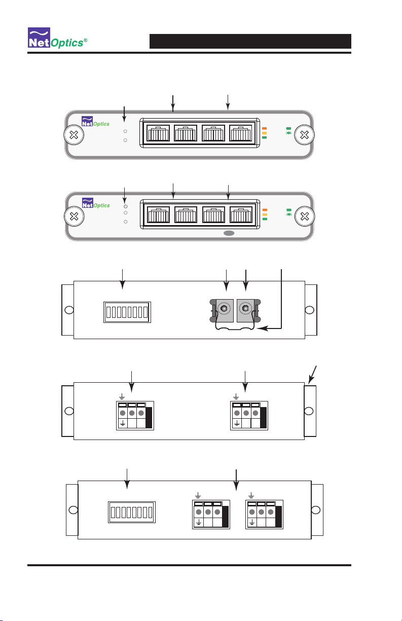
Transparent Access
The Gig Zero Delay Taps and 10/100/1000 BaseT Taps establish permanent
passive access ports without introducing a point of failure or disturbing
other network connections. The Gig Zero Delay Tap either auto-negotiates
communication or uses an external DIP switch to set xed speed and duplexing
parameters. These passive Taps deliver full-duplex monitoring with zero impact
on network trafc around the clock.
True Zero Delay
The breakthrough design of the Net Optics Gig Zero Delay Taps (but not the
10/100/1000 BaseT Taps) ensures zero impact on network trafc when the Tap
experiences a power on or power off event. These devices are the world’s rst
and only 10/100/1000 taps offering true “zero delay” technology.
Highly sensitive network locations can improve monitoring performance with
the innovative features of Net Optics Gig Zero Delay Taps. If power is lost to
other 10/100/1000 taps, the connected devices may introduce delays as they
detect the power loss and try to re-establish their link.
Net Optics’ pioneering design ensures that any loss of power to the Tap is
transparent to the network, and does not affect the ow of trafc through the Tap
– completely eliminating packet delay and loss as potential security issues.

Gig Zero Delay Tap & 10/100/1000BaseT Tap
2
Simply Plug It In
Full-duplex monitoring is a snap when each side of the signal is sent to
a separate NIC on the monitoring device. All network and monitoring
cables necessary for plug-and-play deployment are included with the Tap.
Security and Visibility
Without an IP address, monitoring devices are isolated from the
network, dramatically reducing their exposure to attacks. However, the
monitoring device connected to the Tap still sees all full-duplex trafc
as if it were in-line, including Layer 1 and Layer 2 errors.
Reliability
For extra uptime protection, Net Optics Gig Zero Delay Taps and
10/100/1000 BaseT Taps offer redundant power connections. Should
the primary power source fail, the Tap automatically switches to the
backup power source. Power LEDs on the front of the Tap indicate the
current power source.
Warning! _______________________________________________________
TP-CU3-ZD and TP-CU3-ZD-DC only: This product contains a NiMH
battery. Consult your shipping carrier regarding regulations on safe
shipping of NiMH batteries.
_________________________________________________________________
Warning! _______________________________________________________
TP-CU3-ZD and TP-CU3-ZD-DC only: Electrical Shock Hazard. No
user replaceable parts. Do not open chassis. Return unit to Net Optics
for servicing.
_________________________________________________________________
Note: __________________________________________________________
TP-CU3-ZD and TP-CU3-ZD-DC only: Battery Disposal: Dispose
of used batteries properly. Contact your local authorities regarding
disposal of this battery.
_________________________________________________________________

Gig Zero Delay Tap & 10/100/1000BaseT Tap
3
Key Features
Passive, Secure Technology
• Provides passive access at 10/100/1000 Mbps without data stream interfer-
ence or introducing a point of failure
• Unique Zero Delay technology ensures no packet delay or loss if power is
lost to the Tap
• Permanent in-line installation without affecting network performance
• Link Fault Detect prevents undetected link failures
• Passes all full-duplex trafc (including errors) from all layers for compre-
hensive troubleshooting
• No IP address is needed for the Tap or monitoring device, enhancing moni-
toring security
• Redundant power ensures monitoring uptime
• Fully IEEE 802.3 compliant
• Fully RoHS compliant
Ease of Use
• LED indicators show redundant power and link status
• DIP switches select auto-negotiation of xed speed and duplexing settings
for the Tap
• Front-mounted connectors make installation and operation quick and easy
• Optional 19-inch rack frames hold up to 3 or 12 Taps
• Available with -48VDC power
• Tested and compatible with all major manufacturers’ monitoring devices,
including protocol analyzers, probes, and intrusion detection/prevention
systems
Support
• Net Optics offers technical support throughout the lifetime of your purchase.
Our technical support team is available from 8 am to 5 pm Pacic Time,
Monday through Friday at +1 (408) 737-7777 and by e-mail at
at www.netoptics.com.

Gig Zero Delay Tap & 10/100/1000BaseT Tap
4
About This Guide
This guide explains how to install the Gig Zero Delay Tap and the
10/100/1000BaseT Tap. Please read the Guide before attempting to install
the device.
This guide covers the following models:
• TP-CU3-ZD 10/100/1000 Tap with Zero Delay
• TP-CU3-ZD-DC 10/100/1000 Tap with Zero Delay, -48V DC power
• TP-CU3 10/100/1000 Tap
• TP-CU3-DC 10/100/1000 Tap , -48V DC power
Unpacking and Inspection
Carefully unpack the Gig Zero Delay Tap and check for damaged or missing
parts. The Tap ships with the following:
• (1) Tap device
• (2) power supplies (TP-CU3-ZD and TP-CU3 only)
• (2) power cords (TP-CU3-ZD and TP-CU3 only)
• (1) retainer clip (TP-CU3-ZD and TP-CU3 only)
• (1) network cable, 3 meter, straight-through (purple)
• (1) network cable, 3 meter, cross-over (green)
• (2) monitor cables, 3 meter, straight-through (purple)
• (1) Installation Guide
You may have also ordered a panel for rack mounting and an extended warranty.
Carefully check the packing slip against parts received. If any part is missing or
damaged, contact Net Optics Customer Service immediately.
Warning! ____________________________________________________________
For the TP-CU3-ZD and TP-CU3 models, use only the power supplies pro-
vided by Net Optics for use with this product. Use of other power supplies may
result in a safety hazard that could cause damage or injury.
_______________________________________________________________________

Gig Zero Delay Tap & 10/100/1000BaseT Tap
5
Product Diagrams
Figure 1: Front Panel, Gig Zero Delay Taps (TP-CU3-ZD, TP-CU3-ZD-DC)
Figure 2: Front Panel, 10/100/1000BaseT Taps (TP-CU3, TP-CU3-DC)
Figure 3: Rear Panel AC (external transformer “brick”) power models
Figure 4: Rear Panel DC power model TP-CU3-DC
- + - +
For use with -48 only
- + - +
Terminal BlocksDIP Switch
OFF
1 3 4 5 6 7 82
Figure 5: Rear Panel DC power model TP-CU3-ZD-DC
Monitor A & B
Network A & B
Power
LEDs
®
www.netoptics.com
Network Monitor
10
100
1000
LINK
ACT
1
2
Zero DelayZero Delay
A AB B
Power DC Jacks Retainer ClipDIP Switch
OFF
1 3 4 5 6 7 82
- + - +
For use with -48 only
- + - +
Terminal Block DIP Switch
on side
Terminal Block
Monitor A & B
Network A & B
Power
LEDs
®
www.netoptics.com
Monitor
Network
10
100
1000
LINK
ACT
1
2
Full Duplex TapFull Duplex Tap
A AB B

Gig Zero Delay Tap & 10/100/1000BaseT Tap
6
DC Terminal Blocks
Model TP-CU3-DC has screwless terminal blocks for DC power. Push in the
orange button to open the socket, insert the power wire, and release the button
to clamp the wire into the socket.
Model TP-CU3-ZD-DC has a two piece, screw-type terminal blocks for
DC power. you can unplug half of the terminal block for convenience when
connecting the power wires. Just pull to unplug the removable part, and push it
back in to reconnect it. To connect the power wires, insert a wire into a socket
and tighen the screw to hold it in place.
Figure 6: Two-piece DC terminal block on model TP-CU3-ZD-DC
Note: _______________________________________________________________
The symbols and both indicate safety ground, also called earth or
chassis ground. When attaching the DC power wires, always connect the safety
grounds rst; and when disconnecting the DC power wires, always disconnect
the safety grounds last.
_______________________________________________________________________

Gig Zero Delay Tap & 10/100/1000BaseT Tap
7
LED Indicators
• Power Indicator: Current power source LED illuminates white.
• Link/Activity Indicator: Located in the upper right hand corner. If a good
link is established, the LED illuminates. If there is current activity on this
link, the LED ashes.
• 10/100/1000 Indicator:Located in the upper left hand corner. If the Port
is set to 10 Mbps, the LED illuminates orange. If the Port is set to 100 Mbps,
the LED illuminates yellow. If the Port is set to 1000 Mbps, the LED
illuminates green.
Link Fault DetectTM
The Gig Zero Delay Taps and 10/100/1000BaseT Taps have Link Fault Detect
on the Network ports. The Tap negotiates separately with each side of the full-
duplex link, detecting if either side fails. In the event of a failure, the Tap ceases
negotiation with the remaining side, enabling a clean fail-over to a redundant
network connection (if one is available). Link Fault Detect requires that both
sides of the full-duplex link and communicating at the same speed.
Cabling Guidelines
If both of the devices connected to the Tap network ports are 10/100BaseT
devices that do not support Automatic MDI/MDI-X Conguration (see
explanation, following), then specic cabling must be used in order to
maintain a successful link when power is removed from the Tap. In this case:
• If the link is currently made with a straight-through cable, connect TP-CU3
to the network with two straight-through cables.
• If the link is currently made with a cross-over cable, connect TP-CU3 to the
network with one cross-over cable and one straight-through cable.
In other words, Gig Zero Delay Taps and 10/100/1000BaseT Taps act as
straight-through connections. (The Net Optics 10/100BaseT Taps are different;
they act as crossover connections.)
Automatic MDI/MDI-X Conguration
The need for crossover cabling is eliminated by a feature in the 1000Base-T
standard called Automatic MDI/MDI-X Conguration (IEEE 802.3-2005,
40.4.4). Ports with this feature detect the positions of the transmit and receive

Gig Zero Delay Tap & 10/100/1000BaseT Tap
8
pins, and automatically connect them correctly. All 1000BaseT ports support
this feature, as do many 10/100BaseT ports on newer equipment.
The Gig Zero Delay Taps and 10/100/1000BaseT Taps support Automatic
MDI/MDI-X Conguration on all of its ports. However, when the Tap does
not have power, it passively connects the two network ports so the link
remains active. This passive connection is made straight-through. Therefore,
if both of the devices connected to the Tap network ports are 10/100BaseT
devices that do not support Automatic MDI/MDI-X Conguration, then the
positions of the transmit and receive pins cannot be detected automatically,
and straight through or crossover cables are required (as specied in the previ-
ous list) in order to maintain a successful link.
Connecting to the Network
To connect the Tap to the Network link:
1. Connect Network Port A to the appropriate switch, server or router using a
CAT5e cable.
2. Connect Network Port B to the appropriate switch, server or router using a
CAT5e cable.
3. Verify that the Tap Network Ports are cabled in-line between two devices.
Figure 7: Connecting to the Network
®
www.netoptics.com
Monitor
Network
10
100
1000
LINK
ACT
1
2
Full Duplex TapFull Duplex Tap
A AB B
To switch, server or router To switch, server or router

Gig Zero Delay Tap & 10/100/1000BaseT Tap
9
Connecting to the Monitoring Device
To connect the Tap to the Monitoring device:
1. Supply power to the Tap using the two redundant power supplies included
with the unit. Verify that the Power LED illuminates.
Note: _______________________________________________________________
The second power supply is available to support the ow of trafc to the
monitoring device in the event that the rst power supply becomes
unavailable.
______________________________________________________________________
2. Connect Monitor Port A to the appropriate port on the monitoring device
using a CAT5e straight-through cable. This cable sends the monitoring
device a copy of all of the trafc being received at Monitor Port A.
3. Connect Monitor Port B to the appropriate port on the monitoring device
using a CAT5e straight-through cable. This cable sends the monitoring
device a copy of all of the trafc being received at Monitor Port B.
Figure 8: Connecting to the Monitoring Device
®
www.netoptics.com
Monitor
Network
10
100
1000
LINK
ACT
1
2
Full Duplex TapFull Duplex Tap
A AB B
To monitor NIC
To monitor NIC

Gig Zero Delay Tap & 10/100/1000BaseT Tap
10
DIP Switch Settings
The 8-position DIP switch located on the rear panel or the side of the device
sets its communication parameters, as specied in the following table.
Note: _______________________________________________________________
The settings apply to all ports on the Tap (except for Switch 1, Link Fault
Detect, which applies only to the Network Ports). If you use xed settings,
connected devices must match the settings you select for the Tap.
______________________________________________________________________
Switch Position Description
1ON
OFF
Link Fault Detect (LFD) is active on the Network Ports.
Link Fault Detect (LFD) is inactive on the Network Ports.
2-5 See following table
6
ON
OFF
Full-duplex is active for all ports.
Half-duplex is active for all ports.
If switch 2 is ON, this switch is ignored
7 - Reserved
8 OFF MUST BE OFF
NOTE: To activate, push buttons UP.
(This diagram shows all segments
in the OFF position)
1 3 4 5 6 7 82
ON
LINK
FAULT
DETECT
ON
OFF
ON
OFF
ON
OFF
ON
OFF
FD
HD
ON
OFF
ON
OFF
10
100
1000
ON
OFF
RESERVED
DUPLEX
AUTO
NEGOTIATION
2 3 4 5 Line speed for all ports
ON X X X Auto-negotiation
OFF ON X X 1000BaseT (Gigabit)
OFF OFF ON X100BaseT (100Mbps)
OFF OFF OFF ON 10BaseT (10Mbps)
OFF OFF OFF OFF DO NOT USE
Figure 9: DIP Switch Settings
Note:
If you are using a xed-speed setting, all
devices connected to the Tap should also be set
to that same speed. Furthermore, you should
set only one speed switch to ON. If more than
one speed switch is set to ON, the Tap uses the
fastest speed.
Note (TP-CU3 & TP-CU3-DC only):
Following any modications to the DIP switch
settings, it is necessary to power cycle the Tap
for the changes to take affect.

Gig Zero Delay Tap & 10/100/1000BaseT Tap
11
Specications
Environment
Operating Temperature: 0˚C to 40˚C
Storage Temperature: -10˚C to 70˚C (TP-CU3 and TP-CU3-DC)
-10˚C to 45˚C (TP-CU3-ZD and TP-CU3-ZD-DC)
Relative Humidity: 10% min, 95% max, non-condensing
Power
Power Consumption
TP-CU3-ZD and TP-CU3-ZD-DC: 8W typical, 30W maximum
TP-CU3 and TP-CU3-DC: 8W typical, 10W maximum
Power Supply
Input: 100-240VAC, 0.5A, 47-63Hz
Output: 12V 1.5A (TP-CU3 and TP-CU3-DC)
12V 3A (TP-CU3-ZD and TP-CU3-ZD-DC)
-48V Power Supply
Input: -48V DC typical, -36V DC min, -75V DC max
DC Receptacle: Terminal peak, 12-14 gauge wire
Power Over Ethernet (POE)
Fully compatible with POE applications
The Tap passes POE power (like a cable)
The Tap does not supply or consume POE power
Latency (network-to-network & network-to-monitor)
@ 1000 Mbps: 0.75 µsec
@ 100 Mbps: 1.4 µsec
@ 10 Mbps: 10 µsec
Mechanical
Dimensions: 1.1” high x 9.9” deep x 5.55” wide (TP-CU3-ZD)
Dimensions: 1.1” high x 6.4” deep x 5.55” wide (TP-CU3)
Cable Interface
Copper Cable Type: CAT5e
Link Distance Supported: 100 meters

Gig Zero Delay Tap & 10/100/1000BaseT Tap
12
Connectors
(2) RJ45, 8-pin connectors (monitor ports)
(2) RJ45, 8-pin connectors (network ports)
Certications
Fully RoHS compliant
Fully IEEE 802.3 compliant

Gig Zero Delay Tap & 10/100/1000BaseT Tap
13
19.00
9.90
1.10
5.55
1.73
10.32
.25
5.14
TP-CU3-ZD Dimensions

Gig Zero Delay Tap & 10/100/1000BaseT Tap
14
5.55
1.10
6.40
19.00
1.73
5.14
TP-CU3 Dimensions

Gig Zero Delay Tap & 10/100/1000BaseT Tap
15
Symbols on Product Labels
The symbols found on the product labels are as follows:
Indicates WEEE compliance
Indicates CE compliance
Indicates RoHS compliance
Indicates C-Tick compliance
Indicates VCCI compliance
Indicates MET compliance (U.S.A. safety)
!"#$%&'(&)%"*&
!"#$%&'(!$")*$"('!"+,)-+%+!")!.)(-+).$/+)'",)+0*/1.!2+)3%$3+%(4)$#)"+()$3(!*.)!"*5))(-+)!"#$%&'(!$")6!(-!")(-!.),$*1&+"()$%)
!(+&)!.)*$"#!,+"(!'/7)!().-'//)"$()8+),!.*/$.+,)($)')(-!%,)3'%(4)$%)1.+,)+0*+3()#$%)(-+)31%3$.+)$#)(-+)%+*!3!+"()3%$2!,!"9)')
.+%2!*+)($)"+()$3(!*.)!"*5)$%)#$%)(-+)8+"+#!()$#)"+()$3(!*.)!"*5))4$1%)%+(+"(!$":)3$..+..!$")$%)1.+)$#)(-!.)!"#$%&'(!$")
*$".(!(1(+.)4$1%)'**+3('"*+)$#)(-+.+)(+%&.5
(-!.),%'6!"9)!.)1"318/!.-+,)"$()%+/+'.+,)#$%)318/!*'(!$"
;
)*$34%!9-()!.)84)"+()$3(!*.:)!"*5):))'//)%!9-(.)%+.+%2+,
!"#$%&#'()*$'!(+$,$#-./$0123456$78797777$$,$:::+;-<=><?@A+@=B$,$@CA<=B-DE;-<=><?@A+@=B$$$$$$$$$
1<83
1<83
,
*
8
'
,
*
8
'
!"#$%"&'$()#*++,-./012
F=G-D<$)H;<=A
45IJ4I4K
4JI48I14
+,-./012.3045+
!-<$%><?@A*$';@+$)H;<H$(.HDH*$
(H.?L=D;?H*$KM4M3$N)O
)'P"$$$$$)Q""#$$$$$$RFOS'!T$!%/$$$$$$$$$$$$$$$$$$$$$$$$$$$$F"U+
$$O$$$$$$$1$=L$1$$$$$
)
KM4944M79441
*
RF!$VW/ ,'(+
,'(+
,'(+
(QX$VW/
,'(+
,'(+
F-Y+$VW/
(QX$VW/
O&&F%U"R$VW+/
R-;;?A$(HD>?=
V=G$)ZH:
R-G$)ZH:
F=G-D<$)H;<=A
R-A?[;
\H;H[-B-;<
";[?;--D?;[
(CA<=B-D$)-DY?@-
&D=]C@<?=;
=
1.5”x 1”
Compliancy Label w/ MET
O@<CH.$)?^-
Text & Graphics: Black
Material: MM200SM Silver
Laminate: Flexcon 0M100CM UL Matte
678*&9:;<;;:=<;;>
&
>?:@&A&>&B&,-CD504.EF&54G25&H7&$"!
>
#2I0J0-.J
K2JEL0D30-.
';?<?H.$F-.-HA- 45IJ4I4K
",'
"(%944__ '
(Z?;H$F=Q)$@ZH;[-]$LD=B$a"b$<=$aJ4b 4JI48I14"(%944__ *
#"M K432 NDDL-I21
1b
1+M4b
+4cb$F($23d6
:::+;-<=><?@A+@=B
23456$78797777
,-CD502J&H03O
)P&Q;9:;<>
,%N&,RR?R&8-?&Q;9:;<>
!"#$%&'(#)'%)*+,-#'$%.#/"%012/34%*5%/"'%677%89-'$:%;,'21/#*<%#$%$9=>')/%/*%/"'
5*--*.#<?%/.*%)*<&#/#*<$@%A3B%/"#$%&'(#)'%+1C%<*/%)19$'%"12+59-%#</'25'2'<)'D%1<&
AEB%/"#$%&'(#)'%+9$/%1))',/%1<C%#</'25'2'<)'%2')'#('&D%#<)-9&#<?%#</'25'2'<)'%/"1/
+1C%)19$'%9<&'$#2'&%*,'21/#*<:
">>R9:>

Gig Zero Delay Tap & 10/100/1000BaseT Tap
16
Limitations on Warranty and Liability
Net Optics offers a limited warranty for all its products. IN NO EVENT SHALL NET OPTICS, INC.
BE LIABLE FOR ANY DAMAGES INCURRED BY THE USE OF THE PRODUCTS (INCLUD-
ING BOTH HARDWARE AND SOFTWARE) DESCRIBED IN THIS MANUAL, OR BY ANY
DEFECT OR INACCURACY IN THIS MANUAL ITSELF. THIS INCLUDES BUT IS NOT LIM-
ITED TO LOST PROFITS, LOST SAVINGS, AND ANY INCIDENTAL OR CONSEQUENTIAL
DAMAGES ARISING FROM THE USE OR INABILITY TO USE THIS PRODUCT, even if Net
Optics has been advised of the possibility of such damages. Some states do not allow the exclusion
or limitation of implied warranties or liability for incidental or consequential damages, so the above
limitation or exclusion may not apply to you.
Net Optics, Inc. warrants this Tap to be in good working order for a period of ONE YEAR from the
date of purchase from Net Optics or an authorized Net Optics reseller.
Should the unit fail anytime during the said ONE YEAR period, Net Optics will, at its discretion,
repair or replace the product. This warranty is limited to defects in workmanship and materials and
does not cover damage from accident, disaster, misuse, abuse or unauthorized modications.
If you have a problem and require service, please call the number listed at the end of this section and
speak with our technical service personnel. They may provide you with an RMA number, which must
accompany any returned product. Return the product in its original shipping container (or equivalent)
insured and with proof of purchase.
Additional Information
Net Optics, Inc. reserves the right to make changes in specications and other information contained
in this document without prior notice. Every effort has been made to ensure that the information in
this document is accurate. Net Optics is not responsible for typographical errors.
THE WARRANTY AND REMEDIES SET FORTH ABOVE ARE EXCLUSIVE AND IN LIEU OF
ALL OTHERS, EXPRESS OR IMPLIED. No Net Optics reseller, agent, or employee is authorized
to make any modication, extension, or addition to this warranty.
Net Optics is always open to any comments or suggestions you may have about its products and/or
this manual.
Send correspondence to
Net Optics, Inc.
5303 Betsy Ross Drive
Santa Clara, CA 95054 USA
Telephone: +1 (408) 737-7777
Fax: +1 (408) 745-7719
Email: [email protected]/Internet: www.netoptics.com
All Rights Reserved. Printed in the U.S.A. No part of this publication may be reproduced, transmit-
ted, transcribed, stored in a retrieval system, or translated into any language or computer language,
in any form, by any means, without prior written consent of Net Optics, Inc., with the following
exceptions: Any person is authorized to store documentation on a single computer for personal use
only and that the documentation contains Net Optics’ copyright notice.

© 2011 by Net Optics, Inc. All Rights Reserved.
www.netoptics.com
This manual suits for next models
1
Table of contents
Popular Network Accessories manuals by other brands

Gorgy Timing
Gorgy Timing LEDI Network IN user guide

Paradyne
Paradyne COMSPHERE 6800 Series Multiplexer Management and Configuration Guide

Secomea
Secomea SiteManager 29 Series Resetting guide

WePresent
WePresent SharePod quick start guide

Patton electronics
Patton electronics ipRocketLink 3086FR quick start guide