Spirent SPT-N11U User manual
SPT-N11U / SPT-N12U Power Supply Installation and Removal Instructions |1
P/N 71-008727 Rev A, August 2019
SPT-N11U/SPT-N12U Power Supply
Installation and Removal Instructions
The Spirent SPT-N11U and SPT-N12U mainframe chassis house up to twelve slot power
supplies that are accessible via the rear panel. There are three system power supplies for
the system controller and fans that are not user serviceable.
Each slot power supply operates independently and is responsible for powering a test
module in its designated slot.
Important: The power supplies for the SPT-N11U and SPT-N12U chassis are different
and are not interchangeable between the two models.
• SPT-N11U uses Spirent Power Supply ACC-9020A (500 Watts)
• SPT-N12U uses Spirent Power Supply ACC-9026A (575 Watts)
Warning: These power supplies are NOT hot swappable and power must be removed
from the system before proceeding.
In order to minimize the unpacking and installation weight of the chassis, the chassis ships
with only two slot power supplies installed. The remaining power supplies should be
installed after the system has been unpacked and racked.
To install a power supply in an SPT-N11U or SPT-N12U chassis:
1Make sure the chassis is powered down and that no power cords are connected to the
power cord sockets.
2Remove the rear fan tray panel which contains the power supplies. The fan tray panel
is held in place by two latches that are secured by thumbscrews (Figure 1 on page 2).
SPT-N11U/SPT-N12U Power Supply Installation and Removal Instructions
2|SPT-N11U / SPT-N12U Power Supply Installation and Removal Instructions P/N 71-008727 Rev A, August 2019
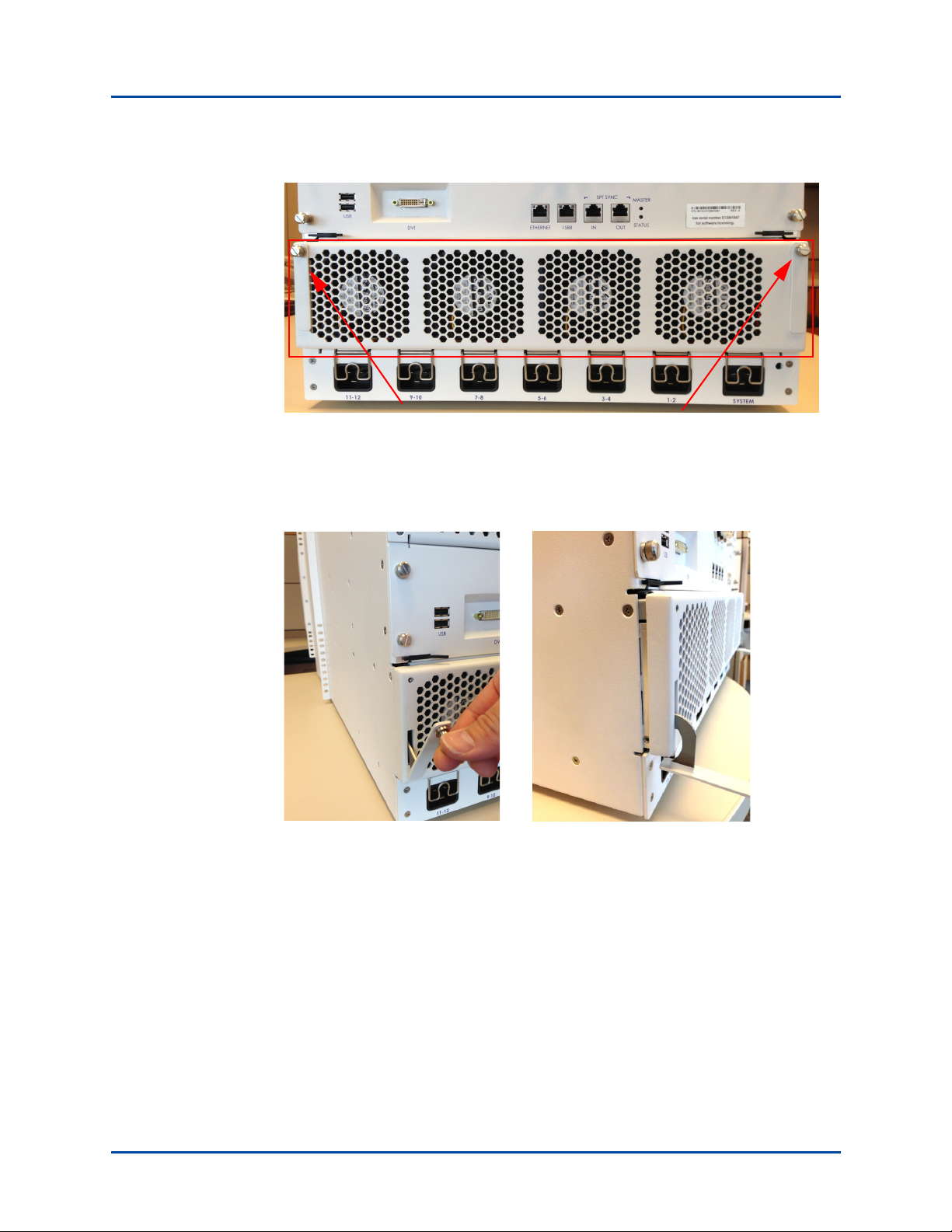
Figure 1. Pull the Spring-loaded Pins
aUnscrew the thumbscrews (see arrows in Figure 1) and gently pull down the
latches to a 90-degree position (Figure 2).
Figure 2. Pull Down the Latches
bThe fan tray panel is friction fit, so it must be pulled outward by gently rocking it
top to bottom, with two hands, as you pull it toward you (Figure 3 on page 3).
Place the fan tray panel aside. The power supply cage is now exposed (Figure 4
on page 3).
SPT-N11U/SPT-N12U Power Supply Installation and Removal Instructions
SPT-N11U / SPT-N12U Power Supply Installation and Removal Instructions |3
P/N 71-008727 Rev A, August 2019
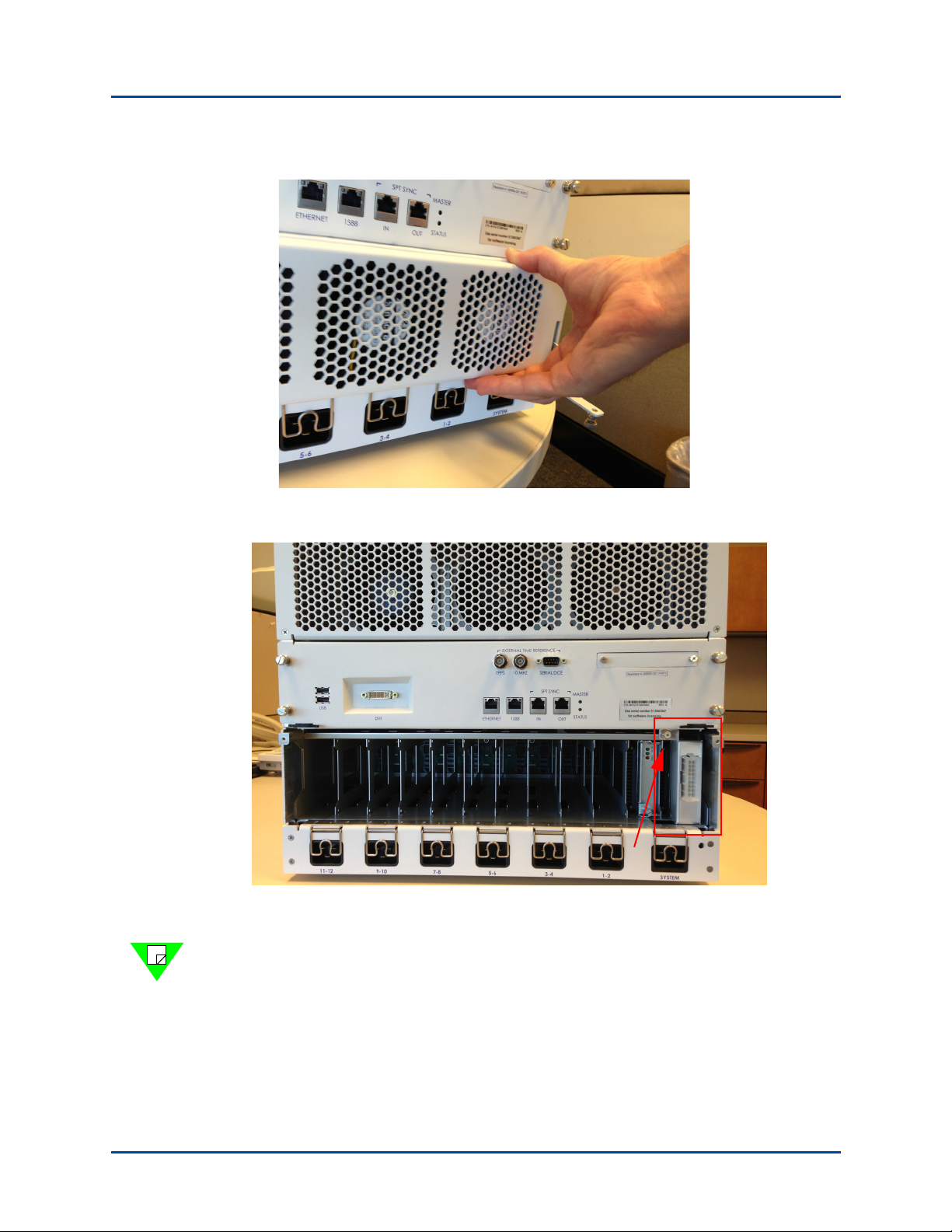
Figure 3. Gently Rock Fan Tray Panel to Remove
Figure 4. Power Supply Cage
Note: The power supply for slot 1 (on the right when viewing from the rear) is behind
the fan tray connector (refer to Figure 4). The slot 1 power supply is normally pre-
installed at the factory, but if you must access it for servicing, you must remove the
phillips-head screw (arrow in Figure 4), and slide the connector out of the way, to
access this power supply.

SPT-N11U/SPT-N12U Power Supply Installation and Removal Instructions
4|SPT-N11U / SPT-N12U Power Supply Installation and Removal Instructions P/N 71-008727 Rev A, August 2019
3Insert the power supplies with the heat sinks facing to the left (Figure 5). The power
supply latch must be pulled out so the flat surface is facing you (see Figure 6).
Figure 5. Heat Sink Facing Left
Figure 6. Flat Surface of Power Supply Latch
4Slide the power supply forward until it stops. It should not require much pressure.
5Fold the latch back towards the power supply so that it catches the bracket and begins
to lever the power supply forward (Figure 7 on page 5).
The latch should sit flush against the power supply.

SPT-N11U/SPT-N12U Power Supply Installation and Removal Instructions
SPT-N11U / SPT-N12U Power Supply Installation and Removal Instructions |5
P/N 71-008727 Rev A, August 2019
Figure 7. Power Supply on Left Ready for Latching to the Cage
Figure 7 shows a power supply on left ready to be secured. The arrows on the right
illustrate where a power supply latch levers into the cage.
6Use a slotted screwdriver to secure the bracket to the power supply housing
(Figure 8).
Figure 8. Secure the Bracket with Slotted Screwdriver
7Re-fit the fan tray panel with the brackets in their unsecured 90-degree position
(Figure 9 on page 6).
aRock the panel top to bottom, with both hands, while pushing it toward the
chassis until it is seated.
bFold up the two hinged brackets and tighten the thumbscrews (Figure 10 on
page 6).

SPT-N11U/SPT-N12U Power Supply Installation and Removal Instructions
6|SPT-N11U / SPT-N12U Power Supply Installation and Removal Instructions P/N 71-008727 Rev A, August 2019
Figure 9. Fan Tray in Place with Brackets in Unsecured Position
Figure 10. Fold up the Brackets and Tighten Thumbscrews
This completes the installation.
To remove the power supplies, reverse steps 2-6.

SPT-N11U/SPT-N12U Power Supply Installation and Removal Instructions
How to Contact Us
SPT-N11U / SPT-N12U Power Supply Installation and Removal Instructions |7
P/N 71-008727 Rev A, August 2019
How to Contact Us
To obtain technical support for any Spirent Communications product, please contact our
Support Services department using any of the following methods:
Americas
E-mail: support@spirent.com
Web: https://support.spirent.com
Toll Free: +1 800-SPIRENT (+1 800-774-7368) (North America)
Phone: +1 818-676-2616
Hours: Monday through Friday, 05:00 to 17:00, Pacific Time
Europe, Middle East, Africa
E-mail: support@spirent.com
Web: https://support.spirent.com
Phone: +33 (1) 6137 2270 (France)
Phone: +44 1803 546333 (UK)
Hours: Monday through Thursday, 09:00 to 18:00, Friday, 09:00 to 17:00, Paris Time
Asia Pacific
E-mail: support@spirent.com
Web: https://support.spirent.com
Phone: +86 (400) 810-9529 (toll-free mainland China only)
Phone: +86 (10) 8233 0033 (China)
Hours: Monday through Friday, 09:00 to 18:00, Beijing Time
Information about Spirent Communications and its products and services can be found on
the main company website at https://www.spirent.com.
Company Address
Spirent Communications, Inc.
27349 Agoura Road
Calabasas, CA 91301
USA
© 2019 Spirent Communications, Inc. All Rights Reserved.

This manual suits for next models
1
Table of contents
Popular Power Supply manuals by other brands

Panasonic
Panasonic AC Geared-Motor M9RZ90GB4LG operating manual

Clas Ohlson
Clas Ohlson SMP-2A quick start guide

Vertiv
Vertiv NetSure 512NGBB quick start guide

Delta Elektronika
Delta Elektronika SM6000 Series manual

FingerTec
FingerTec AdapTec TA Installer's guide

Pulsar
Pulsar Black Power PSBEN 5012E manual


