manuals.online logo
Brands
  1. Home
  2. •
  3. Brands
  4. •
  5. iseg
  6. •
  7. Power Supply
  8. •
  9. iseg ECH 128 User manual

iseg ECH 128 User manual

This manual suits for next models

1

Other iseg Power Supply manuals

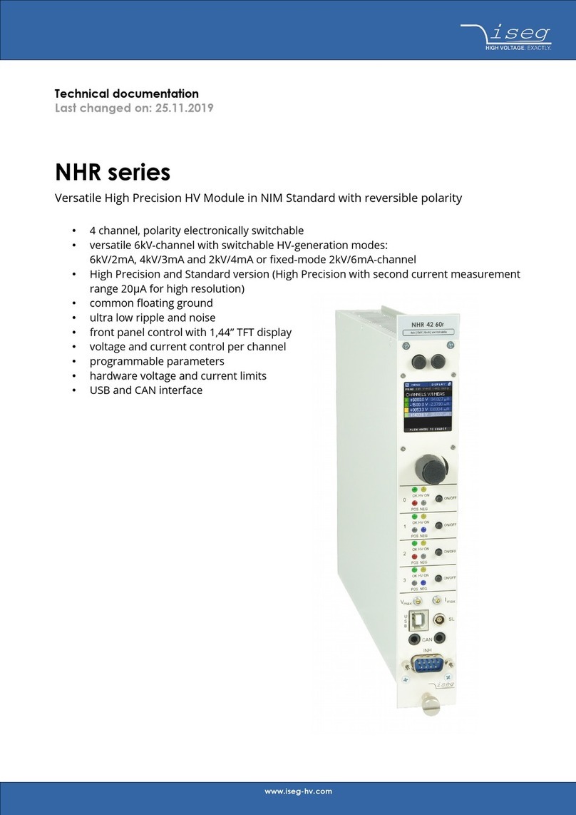
iseg NHR Series Guide

iseg

iseg NHR Series Guide

iseg NHS Series Manual

iseg

iseg NHS Series Manual

iseg EHQ 8007n-F User manual

iseg

iseg EHQ 8007n-F User manual

iseg VHQ 202M User manual

iseg

iseg VHQ 202M User manual

iseg GPS Series Guide

iseg

iseg GPS Series Guide

iseg ECH 238 User manual

iseg

iseg ECH 238 User manual

iseg CalPower EHQ 102M User manual

iseg

iseg CalPower EHQ 102M User manual

iseg EHQ F007n-F User manual

iseg

iseg EHQ F007n-F User manual

iseg EPS Series User manual

iseg

iseg EPS Series User manual

iseg SHQ 122 User manual

iseg

iseg SHQ 122 User manual

iseg NHQ STANDARD Series User manual

iseg

iseg NHQ STANDARD Series User manual

iseg HPS Series User manual

iseg

iseg HPS Series User manual

iseg NHS Series Manual

iseg

iseg NHS Series Manual

iseg EBS F 030 User manual

iseg

iseg EBS F 030 User manual

iseg SHQ Series User manual

iseg

iseg SHQ Series User manual

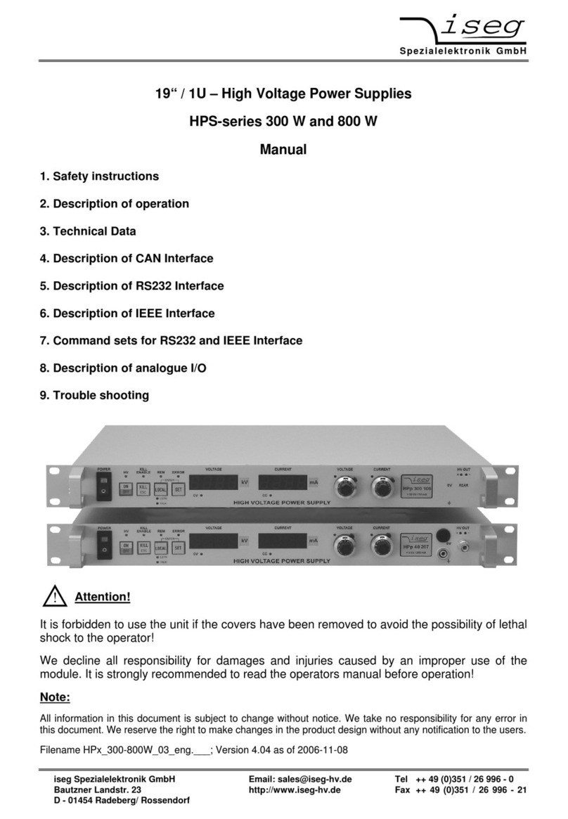
iseg HPS 300 W User manual

iseg

iseg HPS 300 W User manual

iseg HPS 300 W series User manual

iseg

iseg HPS 300 W series User manual

iseg EHQ 9005-F User manual

iseg

iseg EHQ 9005-F User manual

iseg SHR Standard User manual

iseg

iseg SHR Standard User manual

iseg THQ Series Guide

iseg

iseg THQ Series Guide

iseg ECH 238 1200W User manual

iseg

iseg ECH 238 1200W User manual

Popular Power Supply manuals by other brands

Videx 520MR Installation instruction

Videx

Videx 520MR Installation instruction

Poppstar 1008821 Instructions for use

Poppstar

Poppstar 1008821 Instructions for use

TDK-Lambda LZS-A1000-3 Installation, operation and maintenance manual

TDK-Lambda

TDK-Lambda LZS-A1000-3 Installation, operation and maintenance manual

TDK-Lambda 500A instruction manual

TDK-Lambda

TDK-Lambda 500A instruction manual

Calira EVS 17/07-DS/IU operating instructions

Calira

Calira EVS 17/07-DS/IU operating instructions

Monacor PS-12CCD instruction manual

Monacor

Monacor PS-12CCD instruction manual

VOLTIMA MagicBox 15 Installation and operating instructions

VOLTIMA

VOLTIMA MagicBox 15 Installation and operating instructions

Miller Auto Deltaweld 452 owner's manual

Miller

Miller Auto Deltaweld 452 owner's manual

BCP PUOUBK How to install

BCP

BCP PUOUBK How to install

HC 2210 manual

HC

HC 2210 manual

Agilent Technologies 6032A Service manual

Agilent Technologies

Agilent Technologies 6032A Service manual

Radial Engineering SB-48UB user guide

Radial Engineering

Radial Engineering SB-48UB user guide

Puls CT5.241 installation manual

Puls

Puls CT5.241 installation manual

OCZ ZX1250W Technical specifications

OCZ

OCZ ZX1250W Technical specifications

Agilent Technologies 6631B Service manual

Agilent Technologies

Agilent Technologies 6631B Service manual

Power XXL A Series instruction manual

Power

Power XXL A Series instruction manual

HP 6200B Operating and service manual

HP

HP 6200B Operating and service manual

Epson Stylus Scan 2500 Product information sheet

Epson

Epson Stylus Scan 2500 Product information sheet

manuals.online logo
manuals.online logoBrands
  • About & Mission
  • Contact us
  • Privacy Policy
  • Terms and Conditions

Copyright 2025 Manuals.Online. All Rights Reserved.

Spezialelektronik GmbH
iseg Spezialelektronik GmbH Email: sal[email protected] Phone ++ 49 (0)351 / 26 996 - 0
Bautzner Landstr. 23 http://www.iseg-hv.com Fax ++ 49 (0)351 / 26 996 - 21
D - 01454 Radeberg / Rossendorf Germany
Operators manual
Crate ECH 128
Crate ECH 12A
Contents
1. General information
2. Technical Data
3. Pin assignments
Caution!
-The unit must not be operated with the cover removed!
- We decline all responsibility for damages and injuries caused by improper use of the system. It is
highly recommended to read the operator manual before any kind of operation!
Note:
All information in this document is subject to change without notice. We take no responsibility whatsoever for
any error in this document. We reserve the right to make changes in the product design without any notification
to the users.
File name ECH12x_eng.___; Version as of July, 2011
Via Acquanera, 29 22100 Como
tel. 031.526.566 (r.a.) fax 031.507.984
info@calpower.it www.calpower.it
Spezialelektronik GmbH
iseg Spezialelektronik GmbH Email: sal[email protected] Phone++ 49 (0)351 / 26 996 - 0
Bautzner Landstr. 23 http://www.iseg-hv.com Fax ++ 49 (0)351 / 26 996 - 21
D - 01454 Radeberg / Rossendorf Germany 2
1. General information
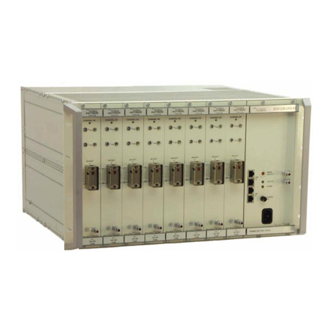
The crates ECH 128 or ECH 12A are able to carry up to 8 or 10 HV-modules in 3U-Eurocassette with H15
connector and one universal interface board. The crates provide the necessary supply voltages and the
connections for all remote control capabilities.
During operation enough air flow has to be given to the unit.
2. Technical data
ECH 128 ECH 12A
8 slots
7 ∗8TE (40,64mm) + 1 ∗max. 12TE (60,96mm) 10 slots / 8 TE (40,64mm)
AC supply voltage Before connecting to the local mains it must be proofed that the nominal line voltage
of this unit is equal to the local mains.
Power: Vin = 100 - 240 V-AC
DC supply voltages + 24 V ( up to 6,25 A) + 24 V ( up to 6,25 A)
Power total max. 150 W
INHIBIT Lemo-hub on the rear, connected with INHIBIT-signal from all HV-modules
TTL level, LOW = active ⇒VOUT-X = 0
Mechanical layout 19“ – 3U Standard BIN (84 TE) / ca. 320 mm depth
Module slot depth 160 mm
CAN-connectors: 9-pin Sub-D
3. PIN assignment
The external CAN-Bus is connected through 9-pin Sub-D connectors on the rear panel:
Input Output PIN Signal Description
2 CAN_L
9-pin 9-pin 3 CAN_GND GND
Sub-D connector Sub-D connector 5 CAN_SHLD Shield
female male 7 CAN_H
Spezialelektronik GmbH
iseg Spezialelektronik GmbH Email: sal[email protected] Phone++ 49 (0)351 / 26 996 - 0
Bautzner Landstr 23 http://www.iseg-hv.com Fax ++ 49 (0)351 / 26 996 - 21
D - 01454 Radeberg / Rossendorf Germany 3
Female H15 - connector on the back plane for the HV module
PIN Name Male H15 - connector / Description
8 VREF V
8-10/12 = 5 V ( 1 mA) Internal reference voltage for an external potentiometer
(Sliding contact on V_VSET or V_ISET))
10/12 PWR_0V Power_0 V (internal connected with HV-GND = LOW-potential)
14 V_IMON Monitor voltage corresponding IOUT: IOUT= 0 to IOUTmax ±1 % ⇒V14-10/12 = 0 to 5 V
20 V_VSET Setting voltage: V20-10/12 = 0 to 5 V ⇒V
OUT = 0 to VOUTmax ±1 %
22 POL Polarity switching (TTL level): open or High-level ⇒positive,
Low-level ⇒negative
24 V_VMON Monitor voltage corresponding VOUT: VOUT= 0 to VOUTmax ±1 % ⇒V24-10/12 = 0 to 5 V
26 PWR_+V V26-10/12 = + 24 V-DC ±5% / max. 0,8 A
28 V_ISET Setting current: V28-10/12 = 0 to 5 V ⇒I
OUT = 0 to IOUTmax ±1 %
(connected with VREF through 10 kΩ)
n.c.: IOUTmax is possible
30 KILL_ENA
TTL-level, High = active ⇒HV_OFF without ramp if signal INHIBIT is active.
Restoring the output voltage is only possible after operating KILL_ENA or PWR_ON.
LOW (or n.c.) ⇒HV according V_VSET or V_ISET, limited to Vmax, Imax resp.
32 INHIBIT TTL-level, LOW = active ⇒VOUT = 0
HIGH (or n.c.) ⇒VOUT according V_VSET (with ramp)
Female 96-pin connector for the universal interface board in the crate ECH 128
H15-slots from 0 (left ) to 7 (right) 96-pin connector for
Multichannel CAN I/O (rightmost)
VS0 to VS7: V_v-set for slots 0 to 7 (H15: 20)
IS0 to IS7: V_i-set for slots 0 to 7 (H15:28)
VM0 to VM7: V_v-monfor slots 0 to 7 (H15: 24)
IM0 to IM7: V_i-mon for slots 0 to 7 (H15:14)
KILLEN : KILL_ENAfor slots 0 to 7 (H15:30)
+24 V: PWR_+Vfor slots 0 to 7 (H15:26)
GND: PWR_0Vfor slots 0 to 7 (H15:10/12)
DB0 to DB7: POL for slots 0 to 7 (H15: 22)
Spezialelektronik GmbH
iseg Spezialelektronik GmbH Email: sal[email protected] Phone++ 49 (0)351 / 26 996 - 0
Bautzner Landstr. 23 http://www.iseg-hv.com Fax ++ 49 (0)351 / 26 996 - 21
D - 01454 Radeberg / Rossendorf Germany 4
Female 96-pin connector for the universal interface board in the crate ECH 12A
H15-slots from 0 (left ) to 7 (right) 96-pin connector for
Multichannel CAN I/O (rightmost)
VS0 to VS7: V_v-set for slots 0 to 7 (H15: 20)
IS0 to IS7: V_i-set for slots 0 to 7 (H15:28)
VM0 to VM7: V_v-monfor slots 0 to 7 (H15: 24)
IM0 to IM7: V_i-mon for slots 0 to 7 (H15:14)
KILLEN : KILL_ENAfor slots 0 to 7 (H15:30)
+24 V: PWR_+Vfor slots 0 to 7 (H15:26)
GND: PWR_0Vfor slots 0 to 7 (H15:10/12)
DB0 to DB7: POL for slots 0 to 7 (H15: 22)
H15-slots 0 (left) to 9 (right)
DB0 to DB7: POL for slots 0 to 7 (H15: 22)
VSO to VS7, IS0, IS1: V_v-set for slots 0 to 9 (H15: 20)
IS2 to IS7: V_i-set for slots 2 to 7 (H15: 28)
VM0 to VM9: V_v-mon for slots 0 to 9 (H15: 24)
IM0 to IM9: V_i-mon for slots 0 to 9 (H15: 14)
KILLEN: KILL_ENA for slots 0 to 9 (H15: 30)
+24V: PWR_+V for slots 0 to 9 (H15: 26)
GND: PWR_0V for slots 0 to 9 (H15: 10/12)
Via Acquanera, 29 22100 Como
tel. 031.526.566 (r.a.) fax 031.507.984

info@calpower.it www.calpower.it