Instruction Manual
1. Marking
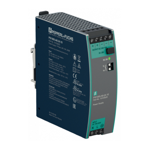
DC Power Supply
PSU1100-J1-DC-*
Equipment protection level Gb
ATEX marking: 1 II 2G Ex eb q IIC T4 Gb
IECEx marking: Ex eb q IIC T4 Gb
Equipment protection level Db
ATEX marking: 1 II 2D Ex tb IIIC T85°C Db
IECEx marking: Ex tb IIIC T85°C Db
DC Power Supply
PSU1200-J2-DC-*
Equipment protection level Gc
ATEX marking: 1 II 3G Ex ec q IIC T4 Gc
IECEx marking: Ex ec q IIC T4 Gc
Equipment protection level Dc
ATEX marking: 1 II 3D Ex tc IIIC T85°C Dc
IECEx marking: Ex tc IIIC T85°C Dc
The *-marked letters of the type code are placeholders for versions of the
device.
Pepperl+Fuchs Group
Lilienthalstraße 200, 68307 Mannheim, Germany
Internet: www.pepperl-fuchs.com
2. Target Group, Personnel
Responsibility for planning, assembly, commissioning, operation,
maintenance, and dismounting lies with the plant operator.
The personnel must be appropriately trained and qualified in order to carry
out mounting, installation, commissioning, operation, maintenance, and
dismounting of the device. The trained and qualified personnel must have
read and understood the instruction manual.
3. Reference to Further Documentation
Specific processes and instructions in this instruction manual require
special provisions to guarantee the safety of the operating personnel.
Observe directives, standards, and national laws applicable
to the intended use and the operating location.
Observe Directive 1999/92/EC in relation to hazardous areas.
Observe directives, standards, and national laws applicable to the
intended use and the operating location.
The corresponding datasheets, manuals, declarations of conformity, EU-
type examination certificates, certificates, and control drawings
if applicable (see datasheet) are an integral part of this document. You can
find this information under www.pepperl-fuchs.com.
For specific device information such as the year of construction,
scan the QR code on the device. As an alternative, enter the serial number
in the serial number search at www.pepperl-fuchs.com.
Due to constant revisions, documentation is subject to permanent change.
Please refer only to the most up-to-date version, which can be found under
www.pepperl-fuchs.com.
4. Intended Use
The device is an apparatus certified for use in hazardous areas rated
according to ATEX directive and IECEx Zones 1 and 21 and Zones 2
and 22 depending on the type version used. The device is also UL listed
for use in Class I and Class II, Division 2 and Class III hazardous areas.
The device is a DC-DC power supply. The device supplies explosion-
protected equipment in the hazardous area. The device provides an
output voltage of 24 V DC based on 18 V to 36 V DC input voltage.
The output power has a derating from 50 °C to 65 °C (80 W to 50 W).
The device is optimized to be used with the following devices:
lDisplay Unit DPU1*00-*
lThin Client Unit TCU1*00-*
lPC Unit PCU1*00-*
The device is only approved for appropriate and intended use.
Ignoring these instructions will void any warranty and absolve
the manufacturer from any liability.
Use the device only within the specified ambient and operating conditions.
Take the intended use of the connected devices from the corresponding
documentation.
The device is an electrical apparatus for hazardous areas.
Devices for which specific conditions of use apply have the X marking at
the end of the certificate number.
5. Improper Use
Protection of the personnel and the plant is not ensured if the device
is not used according to its intended use.
6. Mounting and Installation
Prior to mounting, installation, and commissioning of the device you
should make yourself familiar with the device and carefully read the
instruction manual.
Observe the installation instructions according to IEC/EN 60079-14.
The device must be disconnected from the power supply prior to
installation and maintenance. The power supply may be activated only
after all the circuits required for operation have been fully assembled and
connected.
The device is not suitable for separating hazardous areas.
The device may be installed in gas group IIC.
Safety-relevant markings are found on the nameplate supplied.
Ensure that the nameplate is present and legible. Take the ambient
conditions into account.
Only use accessories specified by the manufacturer.
Protect the circuit against overvoltage (e. g., lightning).
Supply the device with a power supply that meets the requirements for
safety extra-low voltage (SELV) or protective extra-low voltage (PELV).
Ensure that all fasteners are present.
Observe the tightening torque of the screws.
The housing has a ground connection. Connect to this ground connection
an equipotential bonding conductor with a minimum cross section of
4 mm2.
Connect all bare non-energized metal parts to the protective conductor.
Ensure that external ground connections exist, are in good condition, and
are not damaged or corroded.
Ensure that the terminals are in good condition and are not damaged
or corroded.
Only remove the cover in the absence of a potentially explosive
atmosphere.
Mount the device in a weatherproof location.
Ensure that the operating location has a sufficient floor load capacity.
If mounting the enclosure on concrete use expansion anchors.
When mounting the enclosure to a steel framework use vibration resistant
mounting material.
Protect the device against long-term or excessive mechanical vibrations.
The device is heavy. In order to avoid personal injuries or property
damage, make appropriate provisions for the mounting procedure.
Do not damage the breather drain.
Do not cover the breather drain.
Specific Conditions of Use
Mount the device in a location with low electrostatic charge.
6.1. Requirements for Cables and Connection Lines
Install the cables and connection lines in such a way that they are
protected from ultraviolet radiation.
Install cables and cable glands in a way that they are not exposed to
mechanical hazards.
The dielectric strength of the insulation must be at least 500 V according to
IEC/EN 60079-14.
Observe the permissible core cross section of the conductor.
The insulation stripping length must be considered.
When installing the conductors the insulation must reach
up to the terminal.
When using stranded conductors, crimp wire end ferrules
on the conductor ends.
Observe the minimum bending radius of the conductors.
The nominal core cross section of a connected conductor is 2.5 mm2
(solid, finely stranded, and stranded).
6.2. Requirements for Cable Glands
Use only one connection line per opening.
Use only one conductor per terminal.
Adjust the sealing element of the cable gland to the diameter of the cables
and connection lines used.
Ensure that all cable glands are in good condition and are securely
tightened.
6.3. Requirements in Relation to Electrostatics
Avoid electrostatic charges which could result in electrostatic discharges
while installing, operating, or maintaining the device.
Avoid inadmissibly high electrostatic charge of the cables and connection
lines.
Observe the maximum permissible length of cables and connection lines.
Include the metal housing components in the equipotential bonding.
An electrostatic charge poses an ignition hazard in case of discharge.
DOCT-4906D / 2023-06 1 / 2
