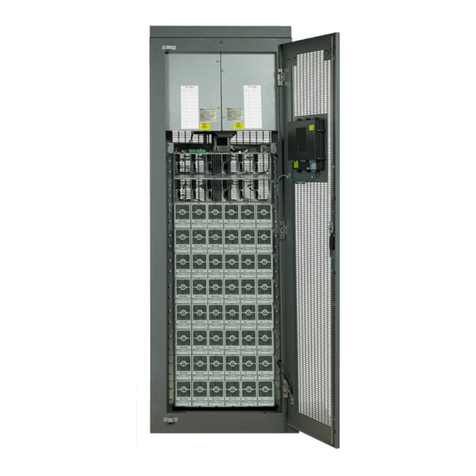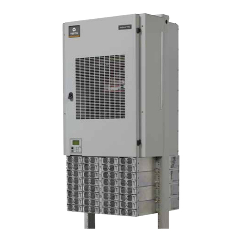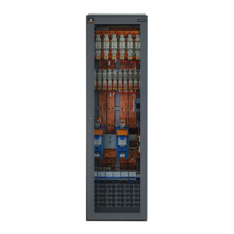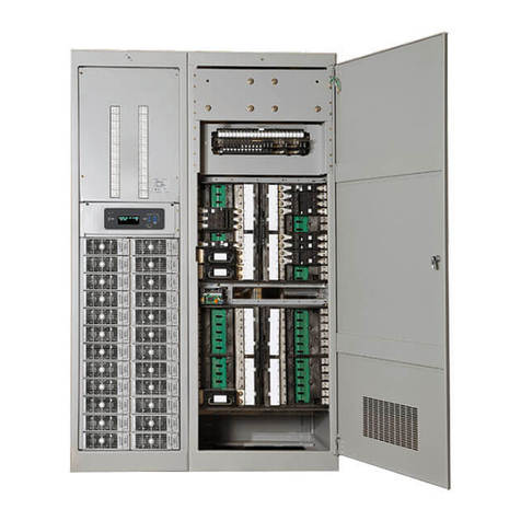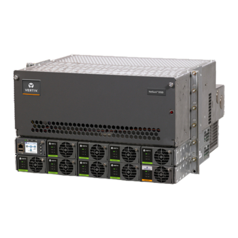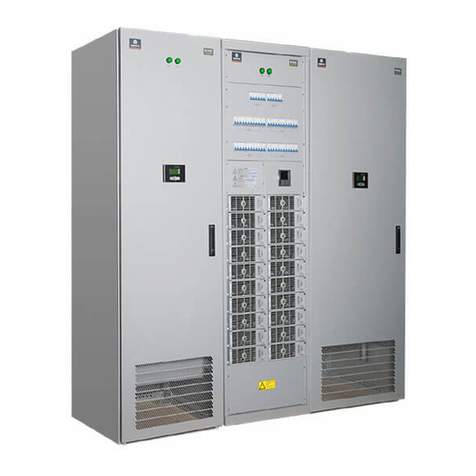
Vertiv™ NetSure™ -48 VDC Power System Quick Start Guide
Proprietary and Confidential © 2023 Vertiv Group Corp.
TABLE OF CONTENTS
Admonishments Used in this Document.............................................................................................................................iv
Important Safety Instructions..................................................................................................................................................v
Safety Admonishments Definitions ..........................................................................................................................................................................................................................v
Safety and Regulatory Statements...........................................................................................................................................................................................................................v
Déclarations de Sécurité et de Réglementation...........................................................................................................................................................................................v
1Customer Documentation Package..................................................................................................................................1
2Physical Installation ...............................................................................................................................................................1
3Installing Circuit Breakers and Fuses.............................................................................................................................2
4Install and Wire Transient Voltage Surge Suppressor (TVSS) Devices ............................................................5
5Electrical Connections .........................................................................................................................................................6
5.1 Important Safety Instructions............................................................................................................................................................................................................................6
5.2 Relay Rack / Cabinet Frame Grounding Connection...................................................................................................................................................................6
5.3 Central Office Ground Connection ...............................................................................................................................................................................................................6
5.4 Ground Connection to a Transient Voltage Surge Suppressor (TVSS) Devices..............................................................................................6
5.5 AC Input and AC Input Equipment Grounding Connections to 588705300 Module Mounting Shelf(s) ..................................6
5.6 External Alarm, Reference, Monitoring, and Control Connections .................................................................................................................................8
5.6.1 Circuit Card and Connector Locations...............................................................................................................................................................................8
5.6.2 System Interface Circuit Card Connections (if required) (List 27 Distribution Cabinet Only)....................................10
5.6.3 IB2 (Controller Interface Board) Connections (if required) .......................................................................................................................... 11
5.6.4 EIB (Controller Extended Interface Board) Connections (if required) ..............................................................................................16
5.7 Controller Ethernet Connection (if required) ...................................................................................................................................................................................21
5.7.1 Connecting a Device or System to the Controller’s CAN Bus (List 27 Distribution Cabinet Only) ........................22
5.8 Load Connections to a List 27 Distribution Cabinet.................................................................................................................................................................23
5.9 Load Connections to a List 7 Distribution Cabinet ...................................................................................................................................................................30
5.10 Battery Connections to a List 27 Distribution Cabinet ...........................................................................................................................................................32
5.11 Battery Connections to a List 7 Distribution Cabinet ..............................................................................................................................................................33
6Installing Rectifier and Converter Modules...............................................................................................................34
6.1 General ..............................................................................................................................................................................................................................................................................34
6.2 System with List 7 Distribution Cabinet...............................................................................................................................................................................................34
6.3 System with List 27 Distribution Cabinet ...........................................................................................................................................................................................34
6.4 Installing Rectifier and Converter Modules ......................................................................................................................................................................................34
7Initially Starting, Configuring, and Checking System Operation.......................................................................37
7.1 Important Safety Instructions.........................................................................................................................................................................................................................37
7.2 Initial Startup Preparation..................................................................................................................................................................................................................................37
7.3 Initially Starting the System .............................................................................................................................................................................................................................37
7.4 NCU Controller Procedure ................................................................................................................................................................................................................................37
7.5 ACU+ Controller Procedure............................................................................................................................................................................................................................ 43

