Spirit Fitnes 1612685 User manual
M
Ma
au
ur
ri
ic
ce
eP
Pi
in
nc
co
of
ff
fs
s1
1(
(8
88
88
8)
)7
70
07
7-
-1
18
88
80
0
1
16
61
12
26
68
85
5T
Tr
re
ea
ad
dm
mi
il
ll
l
S
Se
er
rv
vi
ic
ce
eM
Ma
an
nu
ua
al
l

WARNING:
ALWAYS UNPLUG THE TREADMILL FROM THE ELECTRICAL
OUTLET BEFORE SERVICING THE UNIT.

S
Se
er
rv
vi
ic
ce
eM
Ma
an
nu
ua
al
lM
Ma
au
ur
ri
ic
ce
eP
Pi
in
nc
co
of
ff
fs
s
T
Ta
ab
bl
le
eo
of
fC
Co
on
nt
te
en
nt
ts
s1
1(
(8
88
88
8)
)7
70
07
7-
-1
18
88
80
0
T
Ta
ab
bl
le
eo
of
fC
Co
on
nt
te
en
nt
ts
s1
1
TABLE OF CONTENTS
Table of Contents....................................................................1
Table of Figures......................................................................3
Description .............................................................................4
A ELECTRICAL CONFIGURATION......................................4
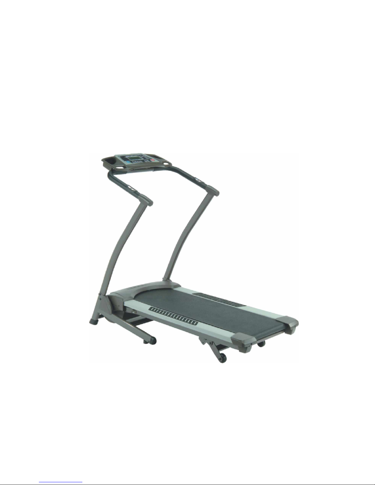
1. 1612685 Treadmill components...................................4
B GENERAL INFORMATION ...............................................5
1. Console.......................................................................5
2. Main controller............................................................5
3. Treadmill motor ..........................................................5
Operation................................................................................7
A WINDOW DISPLAY MODE..............................................7
1. OFF Mode...................................................................7
2. READY Mode.............................................................7
3. SLEEP Mode ..............................................................7
4. RUN Mode..................................................................7
B FUNCTION......................................................................8
1. SPEED........................................................................8
2. TIME..........................................................................8
3. DISTANCE.................................................................8
4. CALORIES.................................................................9
5. PULSE........................................................................9
C FUNCTION BUTTON INMAIN MODE ............................10
1. READY MODE........................................................10
2. SLEEP MODE..........................................................10
3. RUN MODE .............................................................11
D SPEED CALIBRATION...................................................12
1. SPEED Calibration PROCEDURE...........................12
2. SURVEY Calibration................................................12
Troubleshooting....................................................................14
1. General......................................................................14
2. Troubleshooting Matrix.............................................15

S
Se
er
rv
vi
ic
ce
eM
Ma
an
nu
ua
al
lM
Ma
au
ur
ri
ic
ce
eP
Pi
in
nc
co
of
ff
fs
s
T
Ta
ab
bl
le
eo
of
fC
Co
on
nt
te
en
nt
ts
s1
1(
(8
88
88
8)
)7
70
07
7-
-1
18
88
80
0
T
Ta
ab
bl
le
eo
of
fC
Co
on
nt
te
en
nt
ts
s2
2
3. controller debugging form.........................................21
Diagrams and Schematics.....................................................22
APPENDIX A......................................................................26
1. TREADBELT ADJUSTMENT.................................26
APPENDIX B ......................................................................28
1. TREADMILL LUBRICATION................................28
APPENDIX C ......................................................................29
1. RESET SWITCH RESETTING................................ 29
APPENDIX D......................................................................30
1. FUSE REPLACEMENT........................................... 30
APPENDIX E.......................................................................31
1. SPEED SENSOR ADJUSTMENT............................31
2. SERVICE QUESTIONS...........................................31

S
Se
er
rv
vi
ic
ce
eM
Ma
an
nu
ua
al
lM
Ma
au
ur
ri
ic
ce
eP
Pi
in
nc
co
of
ff
fs
s
T
Ta
ab
bl
le
eo
of
fF
Fi
ig
gu
ur
re
es
s1
1(
(8
88
88
8)
)7
70
07
7-
-1
18
88
80
0
T
Ta
ab
bl
le
eo
of
fF
Fi
ig
gu
ur
re
es
s3
3
TABLE OF FIGURES
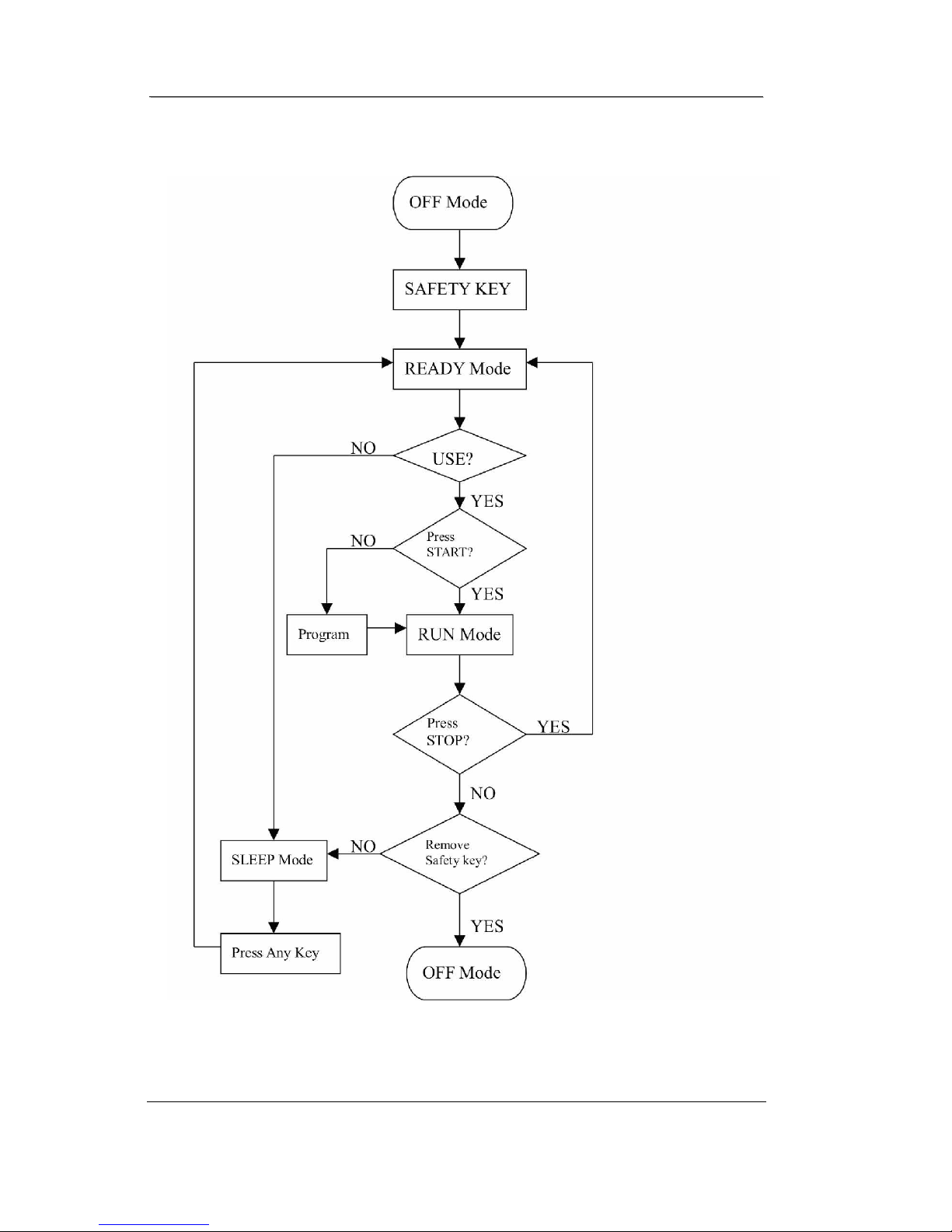
Figure 1 Operational Flowchart..............................................6
Figure 2 Console Layout......................................................22
Figure 3 Mechanical Layout.................................................22
Figure 4 Main Controller information & voltages.................23
Figure 5 Function JK1 connector on Main Controller...........23
Figure 6 Wiring Diagram.....................................................24
Figure 7 Schematic Diagram................................................25
Figure 8 If Treadbelt slips....................................................26
Figure 9 If tread belt shifts too far to the Right.....................26
Figure 10 If tread belt shifts too far to the Left.....................27
Figure 11 Resetting Reset switch .........................................29
Figure 12 Fuse replacement .................................................30

S
Se
er
rv
vi
ic
ce
eM
Ma
an
nu
ua
al
lM
Ma
au
ur
ri
ic
ce
eP
Pi
in
nc
co
of
ff
fs
s
D
De
es
sc
cr
ri
ip
pt
ti
io
on
n1
1(
(8
88
88
8)
)7
70
07
7-
-1
18
88
80
0
D
De
es
sc
cr
ri
ip
pt
ti
io
on
n4
4
DESCRIPTION
A ELECTRICAL CONFIGURATION
Note: Electrical servicing of this treadmill is limited to board
level replacement.
1. 1612685 TREADMILL COMPONENTS
a) Safety key:
Magnetic key that fits in the Console to activate all
functions.
b) Console:
Interface that controls all functions of the treadmill.
c) Main controller:
A circuit board that incorporates the DC power supply and
takes input from the console and sends out appropriate
voltages that control the treadmill functions.
d) Treadmill motor:
A variable speed, reversing 0 - 110 volt D.C. motor that
powers the main running belt.

S
Se
er
rv
vi
ic
ce
eM
Ma
an
nu
ua
al
lM
Ma
au
ur
ri
ic
ce
eP
Pi
in
nc
co
of
ff
fs
s
D
De
es
sc
cr
ri
ip
pt
ti
io
on
n1
1(
(8
88
88
8)
)7
70
07
7-
-1
18
88
80
0
D
De
es
sc
cr
ri
ip
pt
ti
io
on
n5
5
B GENERAL INFORMATION
1. CONSOLE
a) Contains touch controls and LED Display.
2. MAIN CONTROLLER
a) Contains power supply and control circuits.
3. TREADMILL MOTOR
a) Variable speed reversing 0-110 volt DC motor.
b) Has three wires red, black and green.
c) If there is DC voltage on the Red wire (M+) the treadmill
motor will turn clockwise.
d) If there is DC voltage on the Black wire (M-) the treadmill
motor will turn counter-clockwise.
e) The higher the voltage the faster the motor turns.
f) The green wire is ground.
S
Se
er
rv
vi
ic
ce
eM
Ma
an
nu
ua
al
lM
Ma
au
ur
ri
ic
ce
eP
Pi
in
nc
co
of
ff
fs
s
D
De
es
sc
cr
ri
ip
pt
ti
io
on
n1
1(
(8
88
88
8)
)7
70
07
7-
-1
18
88
80
0
D
De
es
sc
cr
ri
ip
pt
ti
io
on
n6
6
Figure 1 Operational Flowchart

S
Se
er
rv
vi
ic
ce
eM
Ma
an
nu
ua
al
lM
Ma
au
ur
ri
ic
ce
eP
Pi
in
nc
co
of
ff
fs
s
O
Op
pe
er
ra
at
ti
io
on
n1
1(
(8
88
88
8)
)7
70
07
7-
-1
18
88
80
0
O
Op
pe
er
ra
at
ti
io
on
n7
7
OPERATION
A WINDOW DISPLAY MODE
1. OFF MODE
a) When user doesn’t insert the SAFETY KEY on the console, the
treadmill enters the OFF Mode and all windows will appear
blank.
2. READY MODE
a) When treadmill power on, all windows will display for 2
seconds, then dots matrix displays the character ODO and
DISTANCE window display total accumulated working
distance, after 2 seconds, dot matrix displays the character
“HRS” and TIME window displays total accumulated working
time, after 2 seconds, dot matrix displays the character “VER”
and SPEED window displays current software version. In
above process, as ODO, HRS and VER, press any key to enter
next step. The led of Manual will be flashing and display
concerning information.
b) TIME, DISTANCE and CALORIES Values will all be saved
when RUN Mode enters READY Mode.
c) In READY Mode, if user doesn’t press any button for 4
minutes it will then enter SLEEP Mode.
3. SLEEP MODE
a) In SLEEP Mode, when START button is pressed then the
treadmill enters READY Mode.
4. RUN MODE
a) In RUN Mode, pressing the “STOP” button and removing the
SAFETY KEY will cause the treadmill stop instantly and enter
OFF Mode.

S
Se
er
rv
vi
ic
ce
eM
Ma
an
nu
ua
al
lM
Ma
au
ur
ri
ic
ce
eP
Pi
in
nc
co
of
ff
fs
s
O
Op
pe
er
ra
at
ti
io
on
n1
1(
(8
88
88
8)
)7
70
07
7-
-1
18
88
80
0
O
Op
pe
er
ra
at
ti
io
on
n8
8
B FUNCTION
1. SPEED
a) SPEED and DISTANCE value display in same window and
pressing “MODE” button will toggle between them.
b) DISPLAY range is 0.0 to 99.9 KPH/MPH.
c) WORK range is 1.0 to 10 MPH.
d) Press “FAST” or ”SLOW” to adjust speed, each increment and
decrement is 0.1MPH/KPM.
2. TIME
a) TIME is either COUNT UP or COUNT DOWN. System preset
is COUNT UP; if user sets the time then timer is COUNT
DOWN.
b) DISPLAY range is 0:00 to 99:59.
c) WORK range is 0:00 to 99:59.
d) COUNT DOWN setup range is 10:00 to 99:00.
e) When TIME is set, the count will go to zero.
f) In RUN Mode, press “STOP” button to save value of time and
enter “RUN Mode” again that value will continue count up
time.
3. DISTANCE
a) DISTANCE and SPEED value display in same window and
pressing “MODE” button will toggle between them.
b) DISTANCE is either COUNT UP or COUNT DOWN. System
preset is COUNT UP; if user sets the time then timer is
COUNT DOWN.
c) DISPLAY range is 0.00 to 999.9.

S
Se
er
rv
vi
ic
ce
eM
Ma
an
nu
ua
al
lM
Ma
au
ur
ri
ic
ce
eP
Pi
in
nc
co
of
ff
fs
s
O
Op
pe
er
ra
at
ti
io
on
n1
1(
(8
88
88
8)
)7
70
07
7-
-1
18
88
80
0
O
Op
pe
er
ra
at
ti
io
on
n9
9
d) WORK range is 0.00 to 999.
e) COUNT DOWN setup range is 0.10 to 999.0.
f) In RUN Mode, press the “STOP” button the DISTANCE value
will still display and save all data. If RUN Mode is entered, the
distance will count up again.
4. CALORIES
a) CALORIES divides into COUNT UP and COUNT DOWN.
System preset is COUNT UP; if user sets the time then timer is
COUNT DOWN.
b) DISPLAY range is 0.00 to 999.9.
c) WORK range is 0.00 to 999.9.
d) COUNT DOWN setup range is 1.0 to 999.0.
e) In RUN Mode, press the “STOP” button to save value of
distance and entering “RUN Mode” again that value will
continue count up time.
5. PULSE
a) DISPLAY range is 0 to 999.
b) WORK range is 40 to 240.
c) If the treadmill doesn’t have a signal for 8 seconds then value
will become “P”.

S
Se
er
rv
vi
ic
ce
eM
Ma
an
nu
ua
al
lM
Ma
au
ur
ri
ic
ce
eP
Pi
in
nc
co
of
ff
fs
s
O
Op
pe
er
ra
at
ti
io
on
n1
1(
(8
88
88
8)
)7
70
07
7-
-1
18
88
80
0
O
Op
pe
er
ra
at
ti
io
on
n1
10
0
C FUNCTION BUTTON INMAIN MODE
1. READY MODE
a) PROGRAM button: User can select “MANUAL” or
PROGRAMS 1 to 3.
b) START button: When pressing “START” button, there will be
5 second final count down on window display, then machine
starts running. In MANUAL, treadmill starts at MIN SPEED
and treadmill starts at program preset value in PROGRAM.
c) STOP button: non-function.
d) MODE button: Press “MODE” button to select TIME,
DISTANCE and CALORIES that can press ”FAST” or
“SLOW” to set count down. If “MODE” button is pressed for 2
seconds the treadmill will clear all value to zero.
e) FAST button: If user doesn’t enter a setting then this button is
non-functional.
f) SLOW button: If user doesn’t enter a setting then this button is
non-functional.
2. SLEEP MODE
a) PROGRAM button: non-functional.
b) START button: Enter the READY Mode.
c) STOP button: non-functional.
d) MODE button: non-functional.
e) FAST button: non-functional.
f) SLOW button: non-functional.
→MANUAL→P-1 →P-2 →P-3 →

S
Se
er
rv
vi
ic
ce
eM
Ma
an
nu
ua
al
lM
Ma
au
ur
ri
ic
ce
eP
Pi
in
nc
co
of
ff
fs
s
O
Op
pe
er
ra
at
ti
io
on
n1
1(
(8
88
88
8)
)7
70
07
7-
-1
18
88
80
0
O
Op
pe
er
ra
at
ti
io
on
n1
11
1
g) LOW SPEED (3 mph/3 km) button: non-functional.
h) MIDDLE SPEED (5 mph/6 km) button: non-functional.
i) HIGH SPEED (7 mph/9 km) button: non-functional.
3. RUN MODE
a) PROGRAM button: non-functional.
b) START button: non-functional.
c) STOP button: press “STOP” button to stop and enter READY
Mode.
d) In “SCAN”, window display mode automatically shifts every
10 seconds.
e) FAST button: Press the button to increase your speed and each
increase is 0.1mph/km. If button is pressed continuously then
speed increases to MAX SPEED quickly.
f) SLOW button: Press the button to decrease your speed and
each decrease is 0.1mph/km. If button is pressed continuously
then speed decreases to MIN SPEED quickly.
g) LOW SPEED (3 mph/3 km) button: Speed will set to (3 mph/5
km) quickly.
h) MIDDLE SPEED (5 mph/6 km) button: Speed will set to (5
mph/6 km) quickly.
i) HIGH SPEED (7 mph/9 km) button: Speed will set to (7 mph/9
km) quickly.

S
Se
er
rv
vi
ic
ce
eM
Ma
an
nu
ua
al
lM
Ma
au
ur
ri
ic
ce
eP
Pi
in
nc
co
of
ff
fs
s
O
Op
pe
er
ra
at
ti
io
on
n1
1(
(8
88
88
8)
)7
70
07
7-
-1
18
88
80
0
O
Op
pe
er
ra
at
ti
io
on
n1
12
2
D SPEED CALIBRATION
1. SPEED CALIBRATION PROCEDURE
a) Power on treadmill.
b) Press “START” and “MODE” button at the same time.
c) Inserts the SAFETY KEY on monitor.
d) Set WHEEL size: Press “FAST” or “SLOW” button to adjust
wheel size value to 1.8 in SPEED window.
e) Km/Mile Mode: Press “STOP” button to exchange to Mile
Mode in SPEED window and the value is “km” “M”.
f) Press “START” button to memorize above setting and enter
next section of setting mode.
g) Set Min SPEED: Press “ FAST” or “ SLOW”button to adjust
minimum speed value to 1.0 in SPEED window.
h) Press “START” button to memorize above setting and enter
next section of setting mode.
i) Set Max SPEED: Press “FAST” or “SLOW” button to adjust
maximum speed value to 13.0 in SPEED window.
j) After calibrating, press “START” button treadmill will
calibrate SPEED automatically.
k) Set Min SPEED: Press “UP” or “DOWN” button to adjust
minimum speed value to 1.0 in DISTANCE/SPEED window.
l) Set Max SPEED: Press “FAST” or “SLOW” button to adjust
maximum speed value to 10.0 in CALORIES/PULSE window.
m) After calibrating, press “START” button treadmill will
calibrate SPEED automatically.
2. SURVEY CALIBRATION

S
Se
er
rv
vi
ic
ce
eM
Ma
an
nu
ua
al
lM
Ma
au
ur
ri
ic
ce
eP
Pi
in
nc
co
of
ff
fs
s
O
Op
pe
er
ra
at
ti
io
on
n1
1(
(8
88
88
8)
)7
70
07
7-
-1
18
88
80
0
O
Op
pe
er
ra
at
ti
io
on
n1
13
3
a) Turn on the power switch, press and hold the MODE and
STOP key meanwhile. Then enter the displaying which is total
accumulated working distance and time.
b) If want to clean the value, press FAST,SLOW,FAST,SLOW
and MODE key in order, then could clean them to back to zero.
c) Press STOP key to back to idle mode.

S
Se
er
rv
vi
ic
ce
eM
Ma
an
nu
ua
al
lM
Ma
au
ur
ri
ic
ce
eP
Pi
in
nc
co
of
ff
fs
s
T
Tr
ro
ou
ub
bl
le
es
sh
ho
oo
ot
ti
in
ng
g1
1(
(8
88
88
8)
)7
70
07
7-
-1
18
88
80
0
T
Tr
ro
ou
ub
bl
le
es
sh
ho
oo
ot
ti
in
ng
g1
14
4
TROUBLESHOOTING
WARNING:
ALWAYS UNPLUG THE TREADMILL FROM THE ELECTRICAL
OUTLET BEFORE SERVICING THE UNIT.
1. GENERAL
a) Do a visual check of all wiring and connections looking for
chafed wires or lose connections.
b) Make sure any wiring is safely positioned and/or secured away
from moving parts.
c) If you find a fuse blown on a circuit board replace the circuit
board.

S
Se
er
rv
vi
ic
ce
eM
Ma
an
nu
ua
al
lM
Ma
au
ur
ri
ic
ce
eP
Pi
in
nc
co
of
ff
fs
s
T
Tr
ro
ou
ub
bl
le
es
sh
ho
oo
ot
ti
in
ng
g1
1(
(8
88
88
8)
)7
70
07
7-
-1
18
88
80
0
T
Tr
ro
ou
ub
bl
le
es
sh
ho
oo
ot
ti
in
ng
g1
15
5
2. TROUBLESHOOTING MATRIX
Condition Reason Solve
When turn on power,
ON/OFF switch isn’t lit. 1. Power cord isn’t plug into outlet.
2. Power cord isn’t plug into unit.
3. The voltage of outlet is too low.
4. Plug or connector of power cord is open.
5. Connector of power cord is broken.
6. Connecting cable disconnected.
7. Breaker tripped.
8. Breaker is broken.
9. ON/OFF switch is broken.
1. Plug the power cord into outlet.
2. Plug the power cord into unit.
3. Check the voltage of outlet.
4. Replace with new power cord.
5. Replace with new power cord.
6. Check if wire is disconnected
, connect
it again.
7. Press the small red button to return to
original status.
8. Replace with new breaker.
9. Replace with new A.C switch.
When insert safe key, no
display on monitor. 1. Haven’t switch ON/OFF switch.
2. Insert the Safe key on wrong position.
3. 9PIN computer connector not plugged in
properly.
4. 9PIN computer cable is broken.
1. Switch the A.C switch.
2. Insert the safe key on right position.
3. Please check the wire and connect
again.
4. Replace with new 9PIN computer
cable.

S
Se
er
rv
vi
ic
ce
eM
Ma
an
nu
ua
al
lM
Ma
au
ur
ri
ic
ce
eP
Pi
in
nc
co
of
ff
fs
s
T
Tr
ro
ou
ub
bl
le
es
sh
ho
oo
ot
ti
in
ng
g1
1(
(8
88
88
8)
)7
70
07
7-
-1
18
88
80
0
T
Tr
ro
ou
ub
bl
le
es
sh
ho
oo
ot
ti
in
ng
g1
16
6
5. Fuse on controller is blown.
6. Varistor on controller is blown.
7. Reed switch of console is broken. (Open)
8. Other components are faulty.
5. Replace with new fuse or controller.
6. Replace with new varistor or
controller.
7. Replace with new reed switch or
console.
8. Replace with new console.
With no safe key but
treadmill could display or
operate.
1. Reed switch of console is broken. (Short)
2. Have other magnetic components on console.
1. Replace with new reed switch or
console.
2. Remove magnetic component beside
safe key.
When press “START”,
treadmill doesn’t start. 1. Motor M+ or M- wire isn’t connected into right
position.
2. Controller is broken. (No power to motor)
3. Motor is broken.
1. Please check and plug again.
2. Replace with new controller.
3. Replace with new motor.
Treadmill stops or shuts
off by itself. 1. House breaker tripped.
2. Treadmill breaker tripped.
3. Treadmill controller fuse is broken.
4. Treadmill controller shut down and LED would
be light. (Controller debugging form)
1. Reset it.
2. Reset treadmill breaker.
3. Replace with new fuse
4. Turn off the AC switch and turn on
power again.
After removing safe key,
treadmill can’t stop. 1. Reed switch of console is broken. 1. Replace with new reed switch or
console.

S
Se
er
rv
vi
ic
ce
eM
Ma
an
nu
ua
al
lM
Ma
au
ur
ri
ic
ce
eP
Pi
in
nc
co
of
ff
fs
s
T
Tr
ro
ou
ub
bl
le
es
sh
ho
oo
ot
ti
in
ng
g1
1(
(8
88
88
8)
)7
70
07
7-
-1
18
88
80
0
T
Tr
ro
ou
ub
bl
le
es
sh
ho
oo
ot
ti
in
ng
g1
17
7
LCDs not bright,
incomplete or imperfect. 1. LCD light is broken.
2. Power to console too low. 1. Replace with new LCD or console.
2. Check AC power is 110-120.
Check power to console. Replace
lower controller.
LCD displays not bright,
incomplete or imperfect. 1. LCD displays are broken. 1. Replace with new console and
calibrate it.
When press “START”
button to start treadmill,
running belt isn’t running
and window displays
“LS”
error message after 8
seconds.
1. Controller experienced unusual shut down; the
S_D light will be always bright. (Controller
debugging form)
2. Motor wires (red, black) aren’t plugged into
controller.
3. Computer cables not connected properly.
4. Computer cables are broken or damaged.
5. Motor belt is broken.
6. Controller is broken.
7. Motor is broken.
8. Console is broken.
1. Turn off power and reset the
treadmill.
2. Plug cable again.
3. Plug the wire again on controller,
connector and console.
4. Replace with new cable.
5. Replace with new motor belt.
6. Replace with new controller.
7. Replace with new motor.
8. Replace with new console.
When press “START”
button to start treadmill,
running belt isrunning but
window displays “LS”
1. Misalignment between
speed sensor and magnet.
2. Magnet missing.
3. Magnet de-magnetized.
1. Adjust the distance to 5mm between
speed sensor and magnet.
2. Replace with new magnet.
3. Use metal material to test the magnet.

S
Se
er
rv
vi
ic
ce
eM
Ma
an
nu
ua
al
lM
Ma
au
ur
ri
ic
ce
eP
Pi
in
nc
co
of
ff
fs
s
T
Tr
ro
ou
ub
bl
le
es
sh
ho
oo
ot
ti
in
ng
g1
1(
(8
88
88
8)
)7
70
07
7-
-1
18
88
80
0
T
Tr
ro
ou
ub
bl
le
es
sh
ho
oo
ot
ti
in
ng
g1
18
8
error message after 8
seconds.
*Speed sensor cable was
broken,(open) console
can’t receive the speed.
4. Speed sensor cable is broken.(short)
5. 9PIN computer cable connected improperly.
6. 9PIN computer cable is broken.
7. Console is broken.
4. Replace with new sensor cable.
5. Plug the cable again on controller,
connector and console.
6. Gray and purple cable got damage,
replace with new cable.
7. Replace with new console.
SPEED windows display
is not 0.5 to 13.0 km Monitor is not calibrated. Calibrate the monitor.
The speed of the belt
doesn’t match console
display.
Monitor is not calibrated. Calibrate the monitor.
TIME window display
“Err” EEPROM is broken. Replace with new console and calibrate
it.
Erratic pulse display. 1. Another chest belt in use around treadmill.
2. Other magnetic field disturbance.
3. Receiver is broken.
1. Check for other chest belt use around
treadmill.
2. Change the position or direction of
treadmill.
3. Replace with new receiver.
After pressing “START”
button, the treadmill stop
immediately.
Controller was broken. Replace with new controller and
calibrate it.
Other manuals for 1612685
1
Table of contents
Other Spirit Fitnes Treadmill manuals


