Spitfire Aeronaut User manual
We recommend our aero-pick modelling
pins, Order No. 7855/02, for holding
parts together during construction.
Introduction:
The model should be assembled following the sequence of the stages of construction described in these instructions.
The laser-cut components are individually numbered. The manufacturing method leaves small tabs on some parts which
have to be cut away using a thin-bladed modelling knife. The dark edges of the laser-cut parts should be rubbed off using
abrasive paper in order to obtain sound glued joints. Check that all components fit accurately before reaching for the glue,
and carry out any minor trimming required. Allow all glued joints to dry out fully before starting the next stage of
construction. We recommend a fast-setting white glue for all joints. If water-soluble glue is used, corrections are possible
simply by moistening the appropriate area, even after the joint has dried. Once painted over, the glue becomes waterproof
in any case. Please take care to prevent adhesive running onto the untreated mahogany parts and any external surfaces
which will be visible on the finished model, as the glue will show up through the final painted finish. We recommend that
you apply a thin coat of sanding sealer (Order No. 7666/02) to the mahogany components before gluing, followed by
rubbing down with 320-grit abrasive paper. The whole of the boat - inside and out - must be given several coats of clear
waterproof boat lacquer before it is placed in the water, as this seals the wood and the glued joints. If you have to glue
parts to areas which have already been lacquered, use two-pack adhesive for those joints.
5
6
6.1
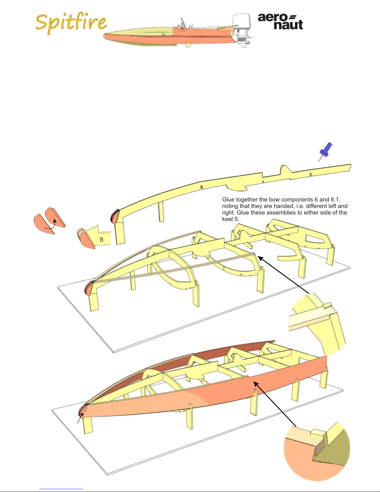
Glue together the bow components 6 and 6.1,
noting that they are handed, i.e. different left and
right. Glue these assemblies to either side of the
keel 5.
8
8
7
Fit the hull sides 8 in the notches of frames 1 to
4, aligning them with the step in frame 3 - as
shown in the detail view - before gluing them to
the stepped shoulder of parts 6.1. Glue the hull
sides 8 to the frames and the stringers 7.
3
6.1
5
Power system:
Aqua Race 60 outboard motor Order No. 7005/01
without electric motor and propeller
28 mm Ø outrunner motor / 3.17 mm shaft / 3000 KV
Two-blade boat propeller, 29 - 31 mm Ø
actronic 40 speed controller Order No. 7002/51
Prog-Card for actronic 40 Order No. 7002/49
2 x 2S 1800 mAh LiPo or 7 NiMH cells
1
2
3
4
5
0
7
7
7
3
Insert frames 1 to 4
in the slots in the
Depron jig 0. Insert
the keel 5 in the
notches in the
frames and the jig 0,
and glue the parts
together. Allow the
glue to set hard, then
glue the stringers 7
in place as shown.
Order Number
1
2
3
3052/00
3
Gluing the internal part 4.1 of frame 4 to the structure
produces a buoyancy chamber in the bow which
renders the boat unsinkable.
Tip
9
11
8
11
8
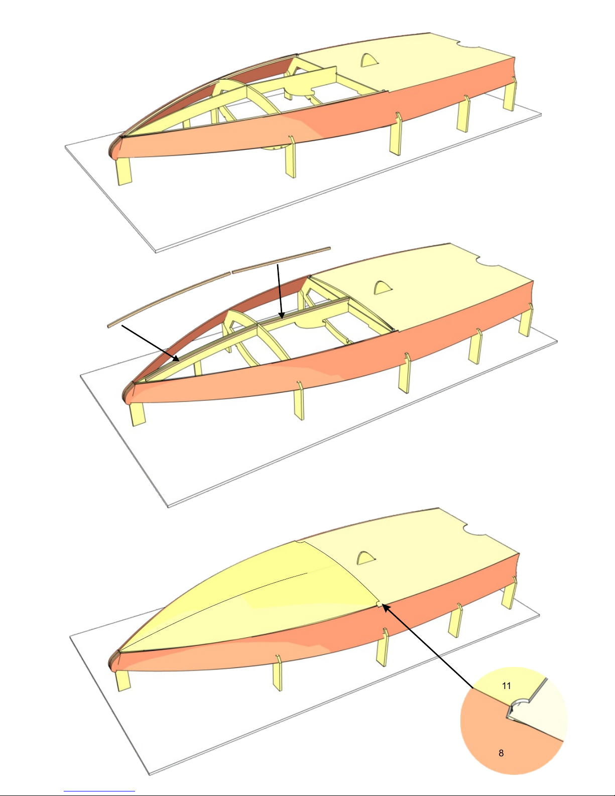
Glue the aft bottom panel 9 to
frames 1 to 3.
1
2
3
Glue the half-frame 10 to the bottom
panel 9, flush with frame 3 and the
step in the hull sides 8.
Glue the reinforcements 5.1 + 5.2 to
both sides of the keel 5.
Glue the forward bottom panel 11
to frame 10, aligning it with the
step in the hull sides 8, then glue it
to the stringers 7.
10 9
3
8
5.1
5.2
5
4
5
6

Remove the support lugs from frames
1 to 4 and the keel 5.
5
1
2
3
41
2
3
4
Glue the stringers 15 in place, followed by
stringers 12, 13 and 14. Glue the
reinforcements 24 to the keel 5.
16
16
17
Glue the cockpit sides 16 and
the cockpit front panel 17 in
place.
12
13
14
14
13
12
15 24
5
7
8
9
Apply several coats of sanding sealer or
boat lacquer to the inside of the hull to
waterproof it, but do not apply the lacquer
to the top edge of the frames and stringers.
10
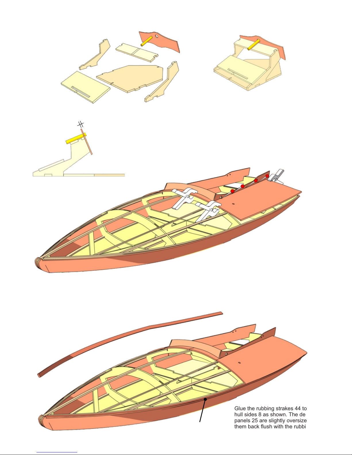
Assemble the control stand, which supports the steering
wheel and servo, from parts 18 to 23. Note that parts 18
and 19 must be at right-angles to each other. The brass
bush 22 should project out of the instrument panel 23 by 1
mm. Place the completed control stand in the hull, but do
not glue it in place; it needs to be detachable.
18
19
19
20
21
22 23
25
8
3
Glue the rubbing strakes 44 to the
hull sides 8 as shown. The deck
panels 25 are slightly oversize; sand
them back flush with the rubbing
strakes when the glue has set hard.
44
44
25
11
12
13
The right and left aft deck panels 25 can now be glued
to the frames and stringers: start by gluing them only to
the area bounded by the stringers 13 and 14, and
secure the panels with spring clips and pins as shown.
Allow the glue to dry out for at least twelve hours, as
the next stage places the glued joints under stress.
Now glue the aft deck panels 25 to the frames and the
hull sides 8, securing them with strips of adhesive tape.
23
22
1 mm

26
27
27
28
29
30 28
31
Roughen the steering column over a length of
9 mm with abrasive paper, then assemble the
steering wheel - consisting of parts 26 to 30 -
using two-pack adhesive.
32
Set the servo to centre,
and fit the output arm on
the servo shaft in the
position shown.
Turn the output arm
through 90°, and fix the
aluminium coupler 32 to
it using the screws 32.1.
33
33.1
Glue the doublers 33.1 to the
rear face of the servo plate
33, and screw the servo to it.
Insert the servo / servo
plate assembly in the slot
of part 21, slip the shaft 31
(with the steering wheel)
through the brass bush
and into the coupler 32,
and align the parts
carefully. Parts 21 and 33
can now be glued together.
Carefully slide the whole
assembly into position in
the hull, and leave it there
until the glue has set hard.
21
22
32
33
Assemble the pulley brackets from parts
34 + 35, and glue these assemblies in
the aft deck panels 25.
34
35 34
39
39.1
40
40
41
25 Glue the transom 39
and the transom
reinforcement 39.1 in
place. Sand the bottom
edge at an angle over a
width of 10 mm as
indicated. Assemble the
brackets 40 in sets of
three, and glue them to
the motor mount 41.
Glue the motor mount assembly 40 + 41 to parts 39
and 39.1 using two-pack adhesive. Fit two screws
43 through frame 1 and the transom 39 from the
inside for additional strength.
14
15 16
17
18
20
21
19
39.1
41
39
40
41
22 The whole model should now be given several coats
of waterproof lacquer until the desired surface
quality is achieved.
Open up the ring-screw 36, fit the
return pulley 37 on it, then close
the loop again. Glue the ring-
screw in the pulley bracket 35.
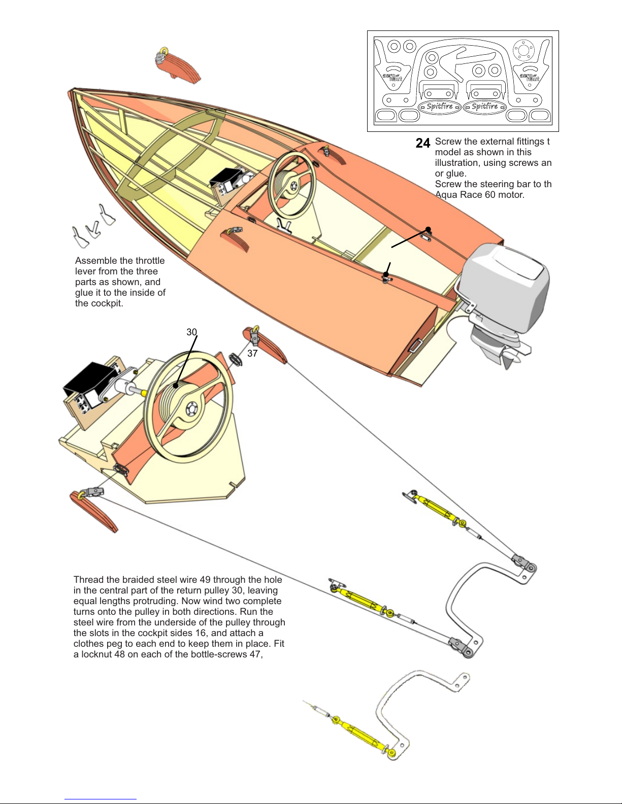
Screw the external fittings to the
model as shown in this
illustration, using screws and /
or glue.
Screw the steering bar to the
Aqua Race 60 motor.
Assemble the throttle
lever from the three
parts as shown, and
glue it to the inside of
the cockpit.
Thread the braided steel wire 49 through the hole
in the central part of the return pulley 30, leaving
equal lengths protruding. Now wind two complete
turns onto the pulley in both directions. Run the
steel wire from the underside of the pulley through
the slots in the cockpit sides 16, and attach a
clothes peg to each end to keep them in place. Fit
a locknut 48 on each of the bottle-screws 47,
unscrew the assemblies as far as possible, and
screw them to the brackets 38. Slip the steel wire
through the front and rear pulleys 37. Thread the
steel wire through the crimp sleeve 50 and the
loop in the bottle-screw, then back through the
crimp sleeve 50. Repeat the procedure on the
opposite side, set the wires under light tension,
then clamp them by crimping both sleeves 50
twice using round-jaw pliers.
36
37
38
38
47
47
48
48
50
50
37
37
30
37
37
49
49
If the motor steering bar is wider
than 70 mm, you will need to fix the
bottle-screws directly to the steering
bar, otherwise there will not be
sufficient travel. Alternatively you
could use a servo with 180° travel.
23
24
25
26
37
37
38
27
28
45
42
Position the fabric accurately, then iron it down onto part 45 using a film iron set to a temperature of 80 - 90°C.
Pull the fabric tight towards the bow, and iron down a small area at that point. Now gently pull the fabric over
the edge on both sides, working step by step so that it becomes taut; iron down the edges as you go. The
fabric can now be heated using the film iron or a heat gun set to 110 - 150°C, so that it shrinks and becomes
tight and smooth. Keep the heat away from the ironed-down edges when shrinking the fabric, otherwise the
heat could soften the adhesive.
The fabric shrinks as follows: 1% at 110°C
2% at 120°C
3% at 130°C
4% at 140°C
5% at 150°C
At 180°C it is also possible to stretch the fabric round curves.
The melting point of the fabric is 250°C.
Cut off the excess fabric along the edges using a sharp blade.
Place the two kneeling boards 42 in the cockpit, and screw them to parts 24.
Glue the fabric support 45 on the stringers.
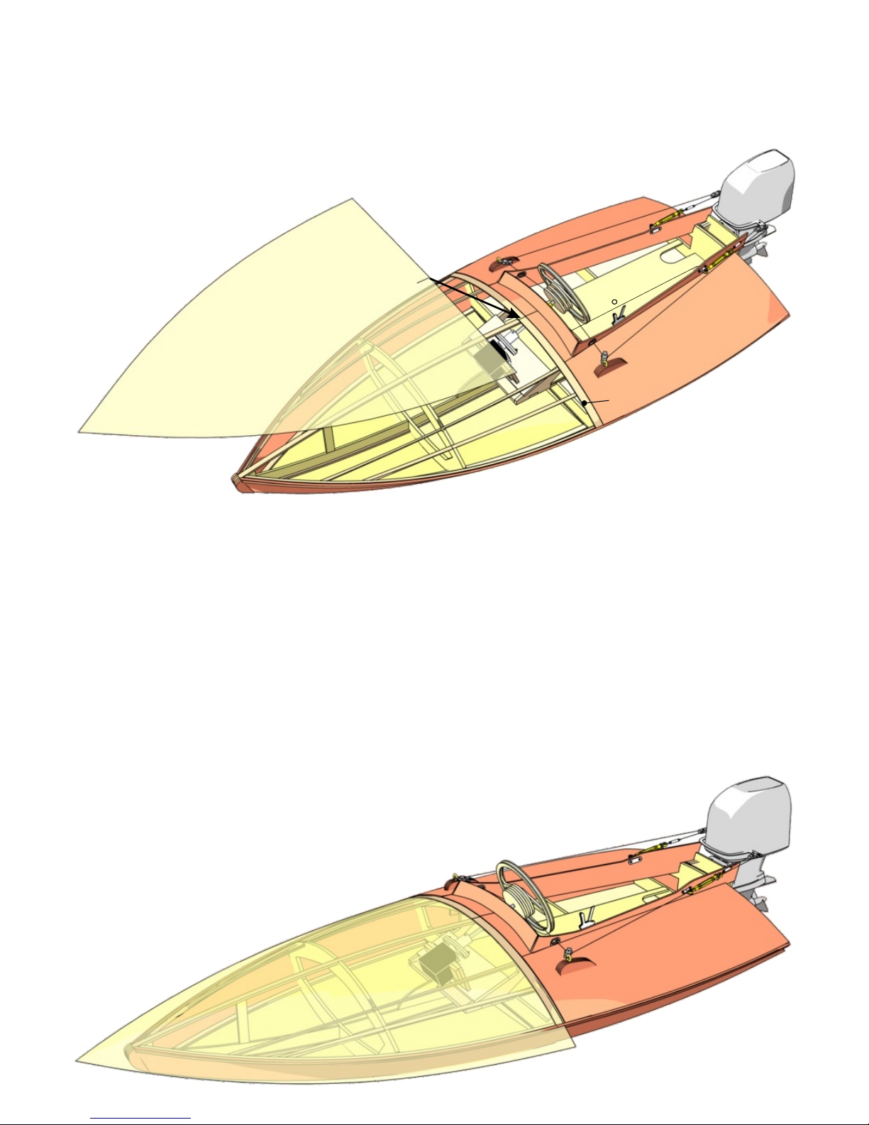
Peel away the silicone backing paper from the underside of the fabric, and lay the adhesive-coated face
on the hull. The fabric is cut to a slightly rounded shape, so that it naturally takes up the curvature of the
deck. The centre of the fabric has a small slit which should coincide with the centre of the deck (see
arrow).

29
We recommend powering the motor with
two 2S LiPo batteries of about 1800 to
2200 mAh, connected in parallel. Install
the packs between frames 2 + 3, and
secure them with hook-and-loop tape. The
boat's Centre of Gravity is 130 mm
forward of frame 1.
130 mm
30 The motor must be aligned in such a way that the centre of
the propeller is exactly level with the rear hull bottom. You
will find a detailed description of setting up the boat in the
Appendix entitled “Trimming”.
Assemble the boatstand from
parts 55 + 56 and glue the joints;
note that the small projecting tabs
of parts 56 face up; the flat rear
part of the model's hull bottom
rests on the stand.
The final stage is to install the receiver and speed controller. When you have checked everything one last time,
you can safely take the boat to the water. Please be cautious when opening the throttle: sudden changes in
throttle could cause the Spitfire to flip over.
2S Lipo
2S Lipo
1
55
55
56
56 31
32

No. Part Material Quantity Size Sheet
0 Jig Depron 1 300 x 600
1 Frame Plywood 1 3 mm 1
2 Frame Plywood 1 3 mm 1
3 Frame Plywood 1 3 mm 1
4 Frame Plywood 1 3 mm 1
5 Keel Plywood 1 2 mm 2
5.1 Keel reinforcement Plywood 2 2 mm 2
5.2 Keel reinforcement Plywood 2 2 mm 2
6 Keel Mahogany plywood 2 1.5 mm 3
6.1 Keel Mahogany plywood 2 1.5 mm 3
7 Stringer Plywood 2 2 mm 2
8 Hull side Mahogany / obechi 2 1.5 mm 4
9 Aft hull bottom Plywood 1 1 mm 5
10 Half-frame Plywood 1 3 mm 1
11 Forward hull bottom Plywood 1 1 mm 5
12 Stringer Plywood 2 2 mm 2
13 Stringer Plywood 2 2 mm 2
14 Stringer Plywood 2 2 mm 2
15 Stringer Plywood 1 2 mm 2
16 Cockpit side panel Mahogany plywood 2 1.5 mm 3
17 Cockpit front panel Mahogany plywood 1 1.5 mm 3
18 Control stand base plate Plywood 1 3 mm 1
19 Control stand side Plywood 2 3 mm 1
20 Control stand link piece Plywood 1 3 mm 1
21 Control stand servo plate Plywood 1 3 mm 1
22 Steering wheel bush Brass tube 1 3 / 4 Ø x 25 mm 7740/41
23 Instrument panel Mahogany plywood 1 1.5 mm 3
24 Reinforcement Plywood 4 3 mm 1
25 Aft deck panel Mahogany plywood 2 1.5 mm 3
26 Steering wheel core Plywood 1 2 mm 2
27 Steering wheel rim Plywood 2 1 mm 5
28 Return pulley disc Plywood 2 1 mm 5
29 Return pulley core Plywood 2 2 mm 2
30 Return pulley centre Plywood 1 1 mm 5
31 Steering wheel shaft Brass 1 3 Ø x 60 mm 7732/30
31.1 Screw + nut Metal 2+2 M1.4 7772/08+7774/51
32 Coupler + grubscrew Aluminium 1+1 M3 x 3 7492/14+7784/31
33 Servo plate Plywood 1 3 mm 1
33.1 Servo plate doubler Plywood 2 3 mm 1
34 Outer pulley bracket Mahogany plywood 4 1.5 mm 3
35 Pulley bracket core Mahogany plywood 4 1.5 mm 3
36 Ring-screw Metal 2 5463/15
37 Return pulley Metal 4 5228/00
38 Bottle-screw bracket Metal 2 5301/01
39 Transom Mahogany plywood 1 1.5 mm 3
39.1 Transom reinforcement Plywood 1 2 mm 2
40 Motor mount bracket Plywood 4 3 mm 1
41 Motor mount plate Plywood 1 3 mm 1
42 Kneeling board Plywood 2 2 mm 2
43 Self-tapping screw Metal 4 2.2 x 9.5 7766/22
44 Rubbing strake Mahogany plywood 2 1.5 mm 3
45 Covering support Plywood 1 1 mm 5
46 Covering Oratex 1 Oversize
47 Bottle-screw Brass 2 5300/28
48 Locknut Brass 6 M2 7773/02
49 Braided steel wire Steel / plastic 1 1500 mm Overlength
50 Crimp sleeve Brass 2 1.5 / 1.1 Ø x 8 mm Overlength
51 Screw Brass 8 M2 x 6
52 Self-locking nut Steel 4 M2 7774/01
54 Etched parts set Nickel-silver

130 mm
Notes on trimming and running characteristics
If a racing boat is to attain as high a speed as possible, combined with safe handling on the water, it is essential to align
the power system correctly and set the appropriate Centre of Gravity. Naturally this applies to the “Spitfire”.
Experts refer to these inter-related adjustments as the boat's “trim”. There are two levels of these settings: the “base trim”,
which represents an efficient starting point, and the “situation trim”; the latter will vary depending on water and wind
conditions, and may differ more or less significantly from the “base trim”. It can also take into account the driver's personal
preference and habits.
Trim
Before adjusting any trim settings it is advisable to place the model on a level surface (table top, workbench, bench seat at
the lakeside), so that you can view it easily from the side at eye-level.
Adjust the height of the outboard motor so that the centre of the propeller shaft is exactly in line with the hull bottom at the
model's stern. The angle of inclination of the outboard motor, which directly affects the thrust angle, should initially be set
to neutral, i.e. the outboard motor is tilted neither forward nor back.
The next step is to set the Centre of Gravity: install all the components in the boat so that it is ready to run, i.e. including
the batteries and - if you wish - the dummy driver.
For the boat's “base trim” the Centre of Gravity should be exactly 130 mm forward of the transom. Measure this distance
using a tape measure or ruler, and mark this point on the side of the hull, e.g. with a small piece of adhesive tape or a
pencil line. If you now place the bottom of the hull on a square wooden strip at the marked position, the hull should remain
exactly horizontal when viewed from the side, i.e. it should not tip forward or back. If the hull inclines forward or back,
adjust the position of the movable internal components in the hull until the Centre of Gravity is correct.
Example: bow tips down = move batteries and / or dummy driver further aft in the model.
Bow rises = move batteries and / or dummy driver further forward in the model.
If it is not possible to set the CG correctly by re-positioning the internal components, you must
add lead ballast to the hull. Add ballast in small increments, and be sure to secure it carefully
using glue or double-sided adhesive tape.
With this CG position your “Spitfire” is set up to run efficiently when the water is calm and
there is little wind. The boat “planes” on the last third of the hull, with the bow and midship
sections out of the water. This gives high speed combined with good steering response and
reliable running characteristics.
If the wind is a little stronger and / or the water is slightly choppy, you will need to push the
bow down onto the water to avoid the boat jumping (pitching): this is achieved by tilting the
outboard motor slightly back, as shown in the drawing. Viewed from the side, the propeller
shaft is now inclined slightly down at the rear, and the revised thrust line presses the bow
down onto the water.
If you want to extract even more speed from the model in calm conditions, then you can try
tilting the outboard motor forward slightly. Viewed from the side, the propeller shaft is now
inclined slightly up at the rear. This raises the bow and midship section further out of the
water, and the boat 'planes' on just the last few centimetres of the hull. The effect is to
increase the boat's speed, but at the expense of slightly more difficult handling and steering
characteristics. In this guise the boat demands experienced hands on the transmitter.

Notes on running the “Spitfire”
Please read through these notes even if you are already an experienced racing boat operator.
The “Spitfire” is a scale model of a home-built racing boat dating from the 1950's, i.e. it is not a purpose-designed racing
model. It is essential to bear this in mind when setting up the boat's CG and power system.
The full-size vessel was capable of 50 miles per hour (= approx. 80 km/hr) in a straight line and under optimum conditions;
when racing with other boats its top speed would naturally be far less. At a scale of 1 : 5.2 this would give a top speed of
35 km/hr for the model; considerably less than 30 km/hr when racing. The recommended power system and a 2S LiPo
battery gave our test models of the 'Spitfire' a top speed of about 25 km/hr combined with safe handling. With this in mind,
we would not recommend trying a 3S set-up until you have already become accustomed to the boat's handling on the
water.
Do not move the throttle stick abruptly when accelerating! The brushless outrunner motor generates sufficient torque to
cause the vessel to rock or wobble under fierce acceleration. You can avoid this by advancing the throttle stick cautiously
and not too quickly. This applies in particular when starting the boat from a standstill.
Boats powered by an outboard motor are steered by swivelling the whole drive shaft, with the result that the steering
response is much more direct. The model responds very differently from a conventional racing boat with rigid shaft and
rudder! You should never apply sudden, pronounced steering commands at full speed. Steering commands should always
be slight when the boat is at high speed. If you wish to carry out a tight turn, first reduce speed markedly, then initiate the
turn, and only accelerate again strongly once the turn is complete.
If the model runs over another boat's wake, it may jump and then strike the water again at an angle; if this should happen,
reduce speed until stability is restored.
If you fit out your “Spitfire” with a dummy driver, you must secure the figure securely so that there is no possibility of
movement when running! An unwanted change in the driver's position could alter the boat's CG to the point where control
is difficult.
However, if you observe the points stated here, the “Spitfire” is safe to operate, and has predictable handling; it will give
you many hours of fun at the lakeside.
We hope you have hours of pleasure with the model!
Notes on the dummy driver
In technical terms it is not essential to install a dummy driver in your “Spitfire”, but there is no doubt that the model looks a
great deal better with a skipper on board, especially since onlookers have little idea of the boat's scale unless a driver
figure is in the cockpit.
The “Spitfire” is designed to accommodate a 1 : 6 scale dummy driver. This is the internationally accepted scale for what
are known as collector dolls, which include both military figures and civilian equivalents. As a result there is a vast range of
complete dummy figures available, together with an extensive choice of clothing and items of equipment. All this means
that there are virtually no limits to the type of dummy driver you can install in your model.
This type of dummy figure generally has many articulated joints, making it easy to position the driver in the appropriate
kneeling attitude in the boat. If you fit a driver to your “Spitfire”, take care to fix the figure securely to the two kneeling
boards (parts 42), using pieces of foam rubber, hook-and-loop tape, rubber bands or screws. You can hook the feet or toes
of the dummy driver in the slots at the rear of the kneeling boards.
We regret that we cannot provide precise instructions for securing the driver in the model, since the variation in driver
figures is so wide.
You can investigate the wide range of collector dolls available by searching for “collector dolls 1:6”, “military figures 1:6”,
etc. on the Internet. These figures are also available at some of the major modelling fairs as well in well-stocked toy shops.

Table of contents
Popular Toy manuals by other brands

eb brands
eb brands Glow Copter XC9893 user guide

RedWing RC
RedWing RC Slick Assembly manual

LGB
LGB 21761 instruction manual

Faller
Faller ST. MARTIN'S GATE IN FREIBURG BREISGAU... Assembly instructions

Tiger Electronics
Tiger Electronics LAZER TAG Deluxe 2 Player System 71094 instruction manual

Faller
Faller Station STUGL-STULS instruction manual

Beechcraft
Beechcraft Travel Air D95A owner's manual

Carf-Models
Carf-Models P-47 Thunderbolt instruction manual

REVELL
REVELL Shelby Mustang GT 350 H Assembly manual

Great Little Trading
Great Little Trading L5172 quick start guide

Reely
Reely Lama 5.1 operating instructions

MTHTrains
MTHTrains Premier J-1e Operator's manual


