Spitznas 2 2418 0010 User manual
Maschinenfabrik GmbH
Spitznas Maschinenfabrik GmbH, Fellerstr.4, D-42555 Velbert, Tel: +49(0)2052 605 0, Fax: +49(0)2052 605 29, www.spitznas.de
Translation of the original operation
manual, compiled: 12.09.13 224180010_BA_en_Version_06 Page 1 of 11
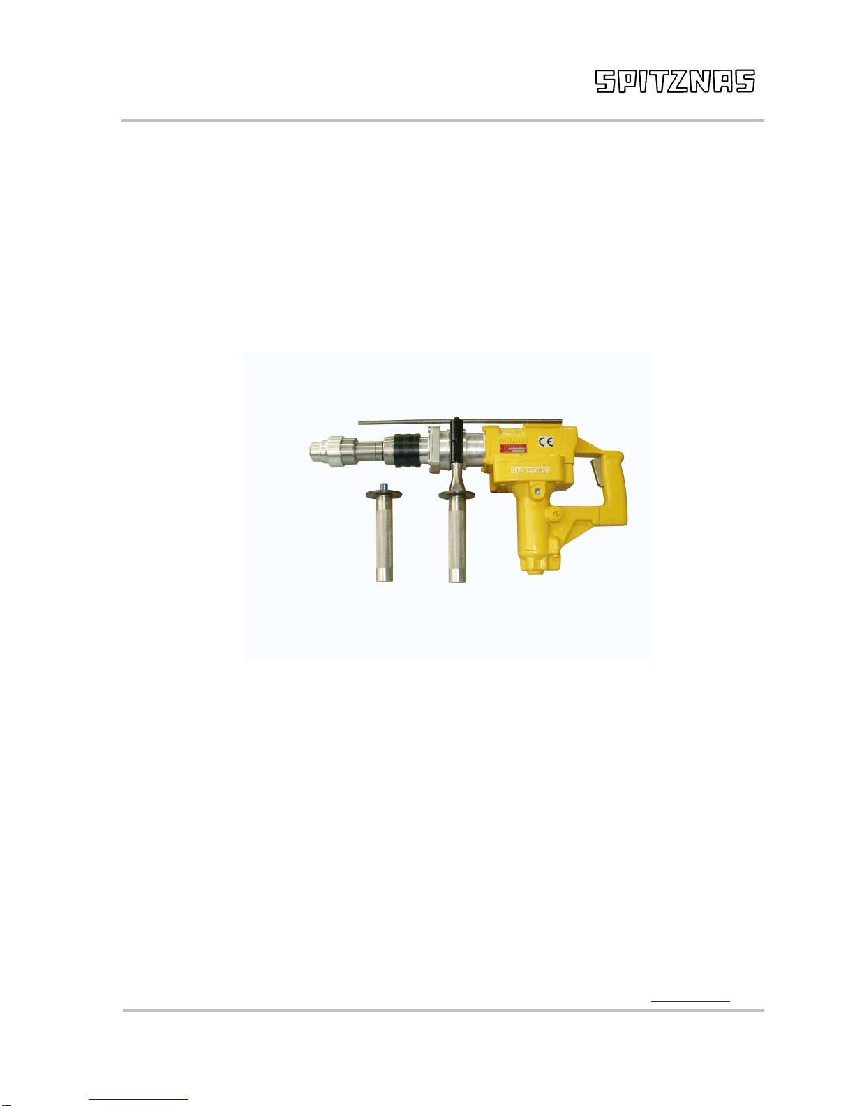
Hydraulic
Rotary Hammer
Type 2 2418 0010
also for underwater application
Illustration can differ from the original
Operation and
Maintenance Manual
Hydraulic
Rotary Hammer Drill
2 2418 0010
Maschinenfabrik GmbH
Spitznas Maschinenfabrik GmbH, Fellerstr.4, D-42555 Velbert, Tel: +49(0)2052 605 0, Fax: +49(0)2052 605 29, www.spitznas.de
Translation of the original operation
manual, compiled: 12.09.13 224180010_BA_en_Version_06 Page 2 of 11
TECHNICAL SPECIFICATIONS
Operating pressure
max. 1137 PSI
max.
80
bar
Oil connection machine SAE PORT No. 8 (3/4 x 16 UNF – 2 B)
Hose coupling set
Flat
-
Star A250
-
OM/OF
-
1/2”BSP
Motor output 1.6 HP 1.2 kW
Oil volume/F
low
4
–
11.9
gallons
/ min
15
-
45
l/min
Water connection ball
valve
R1/4"
R1/4"
ID of hose
0.3937 inch
10 mm
Free spe
ed
2
7
0
rpm
27
0
1/
min
Load speed
2
5
0
rpm
2
5
0
1/
min
Percussion drilling under load
0
-
2300 blows/
min
Drilling range in concrete
0.4724
–
1.9685
inches
∅
12
-
50 mm
Drilling performance in medium-hard concrete 0.7874 dia. =
7.08 cu. in =
14.57
i
nches/ m
in
∅20 mm = 116 cm
3
/min.
= 370 mm/min
Optimum performance in concrete
0.7874
–
1.57
inches
∅
20
-
40 mm
Drilling in
steel with quick
-
release chuck
0.3937
–
0.7874
inches
∅
10
-
20 mm
Drilling i
n wood with quick
-
release chuck
0.3937
–
1.2598 inch
∅
10
-
32 mm
Weight (without hoses)
30.86 lbs
14
kg
Dimensions (length x height x width)
25.2 x 4.92 x 11.73 inches
640 x 125 x 298 mm
Tool holder
SDS
Max
Sound level
at 1 m distance
92 dB(A)
Vibration
at free speed
9
m/s²
Safety clutch for protection a
gainst overloading and accidents
Gears sealed dust tight with central and permanent lubrication (maintenance free)
Adjustable side handle with depth gauge and water flushing
Supplied kit: 1 carrying case, 1 dust guard

Hydraulic
Rotary Hammer Drill
2 2418 0010
Maschinenfabrik GmbH
Spitznas Maschinenfabrik GmbH, Fellerstr.4, D-42555 Velbert, Tel: +49(0)2052 605 0, Fax: +49(0)2052 605 29, www.spitznas.de
Translation of the original operation
manual, compiled: 12.09.13 224180010_BA_en_Version_06 Page 3 of 11
SAFETY INSTRUCTIONS
Any tool can be dangerous.
Please follow these simple procedures.
They are for your protection.
Wear goggles ( chips – risk of injury)
Wear gloves (cutting damages by sharp edged work pieces)
Wear safety shoes
Wear protective clothing
Remove rings, watches, ties etc. that could be torn by the machine.
Dress properly. Do not wear loose clothing or jewellery, it can be caught in
moving parts.
Follow the general current and appropriate Accident Prevention and Safety
Procedures.
Never work under the influence of alcohol, drugs or stronger medication.
Always make sure that you have a safe foothold.
Maintain a proper footing and balance at all time. Never work with the machine
while standing on a ladder or leaning against a scaffold.
Secure the working place well. Use clamps or a vice to fix the work piece. This is
safer than using hands and clears both hands for operating the machine.
Hold the machine tight during operation.
Keep your working area clean and uncluttered.
Keep children away and avoid other persons to come into contact with the
machine.
Switch off the machine if it stops - for any reason - to avoid the unexpected
starting in uncontrolled condition.

Hydraulic
Rotary Hammer Drill
2 2418 0010
Maschinenfabrik GmbH
Spitznas Maschinenfabrik GmbH, Fellerstr.4, D-42555 Velbert, Tel: +49(0)2052 605 0, Fax: +49(0)2052 605 29, www.spitznas.de
Translation of the original operation
manual, compiled: 12.09.13 224180010_BA_en_Version_06 Page 4 of 11
Do not operate the tool if it is damaged, improperly adjusted or not completely
and correctly assembled.
Check hydraulic hose for damage.
Avoid sparks in hazardous environment - created by the drill. Always flush
material and drill for cooling with sufficient water during working.
Do not employ machines by excessive force. Their performance is better and
safer, if they work at the prescribed speed.
Check damaged parts.
Before using the machine, damaged parts or protective devices should be
carefully checked to make sure they work soundly and fulfil the designated
function. Check alignment, connections and attachment of moving parts. Also
check if parts are broken. Parts or protective devices that are damaged should, if
nothing else is mentioned in these operating instructions, only be exchanged or
repaired by qualified personnel. The same applies to defective switches and
valve triggers. If the machine cannot be switched on or off with the valve trigger,
it should not be used.
The use of other accessories, or other additional items than recommended in
these operating instructions, may include the risk of bodily injury.
Only operate the tool after a thorough training or under supervision of a trainer.
Never exceed the maximum operation pressure.
Follow the valid national provisions in the country of application.
Do not operate tool at fluid temperatures above 140° F / 60°C. Operation at
higher temperatures can cause higher than normal temperatures at the tool,
which can result in operator discomfort.
ATTENTION! Never use the hydraulic hose as a lifting handle!

Hydraulic
Rotary Hammer Drill
2 2418 0010
Maschinenfabrik GmbH
Spitznas Maschinenfabrik GmbH, Fellerstr.4, D-42555 Velbert, Tel: +49(0)2052 605 0, Fax: +49(0)2052 605 29, www.spitznas.de
Translation of the original operation
manual, compiled: 12.09.13 224180010_BA_en_Version_06 Page 5 of 11
Use
Intended Use
The machine is designed for drilling into concrete and masonry. The machine is intended to be
used by professional operators. Only authorized and trained personnel may use, maintain and
repair the machine. The personnel has to be especially instructed on the potential dangers. The
working environment can be: construction site, factory, renovation, rebuilding and building.
Manipulation or modifications to the machine are not allowed. Observe the instructions regarding
the operation, care and maintenance in the operation instruction. Dangers can come from the
machines and the auxiliary materials, if improperly handled or used.
Improper Use
Any use deviating from the intended use as described is considered to be improper use.
Working without personal protection equipment
Danger Zones
Operational
condition
----------------
Life phase
Normal function Malfunction Improper use Expected use
Transport Transport of the
machine in an
inoperable
condition
Drop of the
machine Transport of the
machine in an
operable
condition
unknown
Operation
Machine only
works with
actuated switch
Machine runs
without actuated
switch
Switch is blocked
in actuated
condition
unknown
Machine moves
the tool
Tool blocks unknown unknown
Maintenance Filter at hydr.
assembly
Breakdown of the
machine unknown unknown

Hydraulic
Rotary Hammer Drill
2 2418 0010
Maschinenfabrik GmbH
Spitznas Maschinenfabrik GmbH, Fellerstr.4, D-42555 Velbert, Tel: +49(0)2052 605 0, Fax: +49(0)2052 605 29, www.spitznas.de
Translation of the original operation
manual, compiled: 12.09.13 224180010_BA_en_Version_06 Page 6 of 11
Hydraulic system requirements
An operation pressure of 80 bar/ 1137 PSI and a volume flow of 15 l/ min/ 4 gallons/ min is
required to achieve the specified performance data. Volume flow of more than 15 l/ min / 4 gallons/
min is conveyed back to the tank via a bypass. At pressure of more than 80 bar/ 1137 PSI,
a pressure control valve has to be used. (Pressure control valve 2 2406 9900)
WARNING!
Never use your hydraulic tool without a pressure relief valve in line!
The system should not have more than 250 PSI/ 17 bar back pressure measured at the tool end of
the operating hoses. The system conditions for measurement are at maximum fluid viscosity or
400 ssu / 82 centistokes (minimum operating temperature).
The hydraulic system should have sufficient heat rejection capacity to limit the maximum oil
temperature to 140° F / 60° C at the maximum expected ambient temperature. The recommended
minimum cooling capacity is 5 hp / 3.73 kW at a 40° F / 4° C difference between ambient
temperature and oil temperature.
The hydraulic system should have a minimum of 25 micron full-flow filtration. It is recommended
that filter elements be sized for a flow of at least 30 gpm/ 114 lpm for cold temperature startup and
maximum dirt holding capacity.
The recommended hose size is 0.500 inch / 12 mm I.D. to 50 ft / 15 m long and 0.625 inch /
16 mm I.D. minimum up to 100 ft / 30 m long.
The rotary hammer drill return hose must connect directly to the circuit return line and go straight
through the oil filter, thermal valve, and oil cooler to the reservoir. To prevent trapped or reversed
pressure, fluid should not be returned through a blocking or reversing valve.
The rotary hammer drill cannot be operated with the hydraulic flow reversed. Supply (IN) and
return (OUT) hoses must be connected as marked on the sides of the tool ports.
IMPORTANT!
Do not run the tool return hose through stack or directional valves. If the circuit is operated from a
stack valve, tap only the pressure port to the valve. Connect the tool return directly to the return
fluid line.
Your hydraulic rotary hammer drill is an open-center tool. Operate open-center tools from open-
center hydraulic circuits only. Operate closed-center tools from closed-center hydraulic circuits
only.
The rotary hammer drill can be operated with oil only.
Pay attention that the rotary hammer drill is not operated with pressure exceeding the
characteristics indicated, when power is supplied by the system.
Apply pressure reducing valves, otherwise the machine could be damaged or destructed.
When working in a surrounding at 4° C, impact interruptions can occur. Therefore it is
recommended to start the machine and warm it up first.

Hydraulic
Rotary Hammer Drill
2 2418 0010
Maschinenfabrik GmbH
Spitznas Maschinenfabrik GmbH, Fellerstr.4, D-42555 Velbert, Tel: +49(0)2052 605 0, Fax: +49(0)2052 605 29, www.spitznas.de
Translation of the original operation
manual, compiled: 12.09.13 224180010_BA_en_Version_06 Page 7 of 11
Characteristics
Hydraulic fluid Hydraulic oil
Feed pressure 80 bar / 1137 PSI
Volume flow 15- 45 l/ min / 4– 11.9 gallons
Temperature of oil 35°C÷80 °C
Oil filtering ISO purity degree 18/13
Equipment protection and care
Important!
In addition to the a. m. safety instructions, observe the following for equipment protection and care.
Always store the tool in a clean, dry space, safe from damage or pilferage.
Always keep critical tool markings, such as labels and stickers, legible.
Always replace hoses, couplings and other parts with replacement parts recommended by
SPITZNAS.
Supply hoses must have a minimum working pressure rating of 2500 PSI/ 175 bar.
Always use hoses that have an oil resistant inner surface and an abrasive resistant outer surface.
Whenever near electrical conductors, use clean hose labeled and certified non-conductive hose.
Tool repair should be performed by experienced personnel only.
Make sure all couplers are wiped clean before connection.
The hydraulic power supply valve must be in the "OFF" position when coupling or uncoupling
hydraulic tools. Failure to do so can result in damage to the quick couplers and cause overheating
of the hydraulic system.
Do not exceed 13.2 gpm / 50 lpm flow rate. Rapid failure of the tool's internal seals might result.
Make sure the circuit pressure hose (with female quick disconnect) is connected to the "IN" port
below the right-hand side of the tool. The circuit return hose (with male quick disconnect) is
connected to the "OUT" port below the tool center.
Do not reverse the fluid flow from that marked on the tool ports. Flows, when reversed, will not be
limited by the priority flow control valve
Always use the open-center (OC) tool on open-center circuits.

Hydraulic
Rotary Hammer Drill
2 2418 0010
Maschinenfabrik GmbH
Spitznas Maschinenfabrik GmbH, Fellerstr.4, D-42555 Velbert, Tel: +49(0)2052 605 0, Fax: +49(0)2052 605 29, www.spitznas.de
Translation of the original operation
manual, compiled: 12.09.13 224180010_BA_en_Version_06 Page 8 of 11
OPERATION INSTRUCTIONS
Do not exert undue pressure on the machine. This will not increase its performance. Just position
the bit and guide it into the hole.
Placing the machine into the box
Make sure the adjusting sleeve is locked at the setting "rotary hammer drilling".
Side handle
This can be turned through 360° and clamped in any desired position.
Depth gauge
Press unlock button, adjust the depth gauge and release button.
Lubrication of shank end
Occasionally clean shank ends and spray sparingly with lubricant sprayer. Do not spray into the
chuck.
Bild 1 Bild 2 Bild 3 Bild 4 Bild 5
Drilling in explosive surroundings
Fig.1: The drill must be water cooled to avoid sparks. Water connection on ball valve
Rotary hammer drilling
Fig.2: Pull back the adjusting sleeve and turn it clockwise to lock. Do not use the quick-release
chuck at this setting because drills and tools will be damaged.
Fig.3: Pull back the locking sleeve and insert the drill. Turn the locking sleeve until it snaps back
into the outset position. Press the machine against the work surface before switching on otherwise
the tool will not hammer. If the drill sticks in the hole, withdraw and reinsert it several times when
drilling.
Fig.4: When starting to drill into brittle materials (tiles etc), unlock the adjusting sleeve to "rotary
drilling only", hold the machine by the adjusting sleeve and press it slowly against the work surface
until it hammers weakly. Hold and continue to drill the hole. Switch off the machine briefly and
relock the adjusting sleeve.
Rotary drilling only
Fig. 5: Unlock the adjusting sleeve. The quick-release chuck is used at this setting. Commercially
available twist drills can be used in the quick-release chuck.
Cold Weather Operation
If the machine is to be used during cold weather, preheat the hydraulic fluid at low engine speed.
When using the normally recommended fluids, fluid temperature should be at or above 50 °F/10 °C
(400 SSU/ 82 centistokes) before use. Damage to the hydraulic system or the machine can result
from use with fluid that is too viscous or too thick.
(400 SSU/ 82 centistokes) before use. Damage to the hydraulic system or the machine can result
from use with fluid that is too viscous or too thick.

Hydraulic
Rotary Hammer Drill
2 2418 0010
Maschinenfabrik GmbH
Spitznas Maschinenfabrik GmbH, Fellerstr.4, D-42555 Velbert, Tel: +49(0)2052 605 0, Fax: +49(0)2052 605 29, www.spitznas.de
Translation of the original operation
manual, compiled: 12.09.13 224180010_BA_en_Version_06 Page 9 of 11
OPERATING INSTRUCTION FOR UNDERWATER TOOLS
Before working under water
•Check the machine with regard to leakages
•Check the machine regarding functioning of all parts (drilling, striking, actuating valves, etc.)
•Spraying of all moving parts with spray OKS 8604 (or similar).
•Fitting the tools with grease.
After having worked under water
•Clean the machine
•Dry the machine by blowing out with compressed air
•Spraying of all moving parts with spray OKS 8604 (or similar).
For additional information refer to the machine specific operation and maintenance manual as
well.
For a long lasting operation of the machine we recommend a regular (every 3 months) general
overhaul by the company SPITZNAS.
Spray OKS 8601: Spitznas-part no. 9 9902 0120
Maintenance Instruction
Good maintenance practice keeps the tool on the job and increases its service life.
The most important maintenance practice is to keep the hydraulic fluid clean at all times.
Contaminated fluid causes rapid wear and/ or failure of internal parts.
The proper quantity of grease is very important from the point of good lubrication and low heat
generation. The grease quantities listened in the following table must be complied with:
Grease Quantity in grams
In the crank casing 5
In the bevel gear 5
In the spur gear 10
In the planetary gear 10
Grease SPITZNAS reference no. 9 9902 0130 (400 g), 9 9902 0250 (100 g)

Hydraulic
Rotary Hammer Drill
2 2418 0010
Maschinenfabrik GmbH
Spitznas Maschinenfabrik GmbH, Fellerstr.4, D-42555 Velbert, Tel: +49(0)2052 605 0, Fax: +49(0)2052 605 29, www.spitznas.de
Translation of the original operation
manual, compiled: 12.09.13 224180010_BA_en_Version_06 Page 10 of 11
Maintenance of Hydraulic Tools
Only proper maintenance can
ensure constant performance,
reduction in wear and thus, a
decrease in operating costs and
an increase in service life.
Our hydraulic tools are equipped
for an operating pressure of up
to 100 bar. Regulator setting for
a lower operating pressure is
possible.
The tools should not run empty,
because this results in heat and
higher wear of the output section
and the tool holder.
The hydraulic oil should be
clean. This is ensured by
professional equipment.
Clean the connecting parts
before connecting the hydraulic
hoses.
For an economic use of the
hydraulic tools the required sizes
of pipe, fittings and hoses have
to be adjusted.
Proper greasing of the gear and
the tool heads is a must. See the
operation manual on this.
After finishing the work the tools
have to be cleaned and
protected against corrosion.
Visible grease nipples are
provided for regular lubrication of
the gears with a grease gun, or
the gearboxes have a long term
greasing.
Note the following for grease
lubrication: Every 60 hours of
operation check striking
mechanism, friction bearings
and antifriction bearings; if
necessary, grease them. Every
300 hours of operation grease
the gears and antifriction
bearings anew. In the case of
impact wrenches, use a grease
gun to grease the anvil guide
before beginning daily work, or
every 6-8 hours.
All inner parts of the drive (tool
holder must be lubricated before
storing for longer periods of time
in order to prevent rusting. It is
recommended to check the
vanes and bearings at regular
intervals. Store tools in dry
rooms only.
Grease to be used:
In general: SAE 5 W to SAE 10
For impact wrenches without gear only
SAE 5 W
For saw chain greasing on chain saws:
Machine oil with adhesive additive,
viscosity:
c ST 49-55’ (6,5-7,5 E)/ 50°C
GREASE (free of acids and
resins) Multi-purpose greases for
antifriction
and friction bearings and
gears
Special greases for high-speed miter
gears
Designation in accord. with DIN
51502
Consistency class (DIN 51818)
Saponification type
Dripping point
Worked penetration
Temperature range
K L 2 k
2
Lithium
185 °C
265 to 295
-25°C to + 125°C
G 000 h
00
Sodium
145°C
400 bis 410
-25°C bis + 100°C
For the operation of the hydraulic motor we recommend high-class hydraulic oil, e. g. HLP 46,
depending on the case of operation (temperature).

Hydraulic
Rotary Hammer Drill
2 2418 0010
Maschinenfabrik GmbH
Spitznas Maschinenfabrik GmbH, Fellerstr.4, D-42555 Velbert, Tel: +49(0)2052 605 0, Fax: +49(0)2052 605 29, www.spitznas.de
Translation of the original operation
manual, compiled: 12.09.13 224180010_BA_en_Version_06 Page 11 of 11
Spare Parts and Accessories
Only original spare parts may be used. There is no warranty for damages and liability is
disclaimed, if non-original spare parts and accessories are used.
The repairing of the machine is allowed authorized expert companies only.
The accessories applicable with our machine are listed in our brochure.
Troubleshooting
Problem Cause Remedy
a Machine does not
start No hydraulic connection
Connecting and opening of the
hydraulic line
Correct connection of hoses
b Machine rotates too
slowly Operating pressure too low
Increase operating pressure (on the
machine) to 140 bar
c Gearbox makes strong
noise Contact authorized expert company
d Other problems Contact authorized expert company
D e c l a r a t i o n o f C o n f o r m i t y
as defined in the European Union Machine Directive 2006/42/ EC
for usable machines
We, the company
SPITZNAS Maschinenfabrik GmbH, Fellerstraße 4, 42555 Velbert– Langenberg,
declare that the following product
Description: Hydraulic Hammer Drill
Model : 2 2418 0010
complies with the provisions of the European Union Machine Directive 2006/42/ EC
and conforms to the following standards or standardized documents:
DIN EN ISO 12100
DIN EN ISO 11148-5
Name of the authorized person for documentation: Mr. Simon Witt
Address of the authorized person for documentation: see manufacturer’s address
42555 Velbert, 11.02.13
Table of contents


