Atlas Copco Secoroc QLX Series Specifications

Secoroc Rock DrillingTools
SECOROC QLX DTH HAMMERS
QLX 35/40/50/55/60/60 OG/65/100
Operator’s instructions
Spare parts list

2
CONTENTS
INTRODUCTION...........................................................3
SAFETY.....................................................................4–5
INSTALLATION AND OPERATION...........................5–6
DTH SETUP CHOKE PLUG ...........................................7
Bailing Velocity Requirements
Hydrocyclone set up – QLX 100
Maximim fluid removal capacity
New bit and chuck
DTH SETUP ...................................................................8
Makeup torque and backhead closure
DRILL LUBRICATION........
........................................8–9
Lubrication guidelines and specifications
Lubricators
Lubrication check
Water injection
DRILL OPERATION........ .........................................9–11
Drilling with foam
Collaring
Rotation speed
Feed force (hold down and hold back)
Rotation torque
Hole cleaning, flushing and dust suppression
Dry drilling
Wet drilling
Bit changing
Process instructions
MAINTENANCE AND REPAIR ...............................12–17
Follow instructions
DTH Service
Disassembly
Assembly
Disassembly QLX 100
Assembly QLX 100
DTH inspection
Rock Drill Oil
TROUBLESHOOTING GUDE ...... .........................17–19
TECHNICAL SPECIFICATIONS ............................22–26
PARTS LIST...... .....................................................27–32
Secoroc QLX 35
Secoroc QLX 40
Secoroc QLX 50/55
Secoroc QLX 60/65
Secoroc QLX 60 OG
Secoroc QLX 100

3
INTRODUCTION
The QLX series
READ THIS MANUAL CAREFULLY to learn how to operate and
service your DTH hammer correctly. Failure to do so could result
in personal injury or equipment damage. Consult your Atlas
Copco Secoroc dealer if you do not understand the instructions
in this manual or need additional information.
This manual should be considered a permanent part of the DTH
hammer, and should remain with the DTH hammer and available
for reference at all times.
WARRANTY is provided as part of Atlas Copco Secoroc
support program for customers who operate and maintain
their equipment as described in this manual.
MEASUREMENTS in this manual are given in both Imperial
and Metric units, and are used to provide additional worldwide
understanding. Metric units are shown between parentheses
‘’( )’’. Use only correct replacement parts and fasteners.
The instructions, illustrations, and specifications in this
manual are based on the latest information available at time
of publication. Your DTH hammer may have improvements and
options not yet contained in this manual.
ABBREVIATIONS used throughout this manual.
acfm Actual Cubic Feet per Minute
API American Petroleum Institute
CCentigrade
dia. Diameter
deg. Degree
FFahrenheit
ft. Feet
ft.-lb Foot Pounds
gpm Gallons per Minute
in. Inches
kg kilogram
l Liter
lbs. Pounds
lpm Liters per Minute
mMeter
mm Millimeter
mm Hg Millimeters of Mercury
m3/min Cubic Meters per Minute
psi Pounds per Square Inch
psig Pounds per Square Inch Gauge Pressure
rpm Revolutions per Minute
scfm Standard Cubic Feet per Minute
m/s Meters per Second

4
SAFETY
Follow instructions
Carefully read all safety messages in this manual and on your
machine´s safety labels. Keep safety labels in good condition.
Replace all missing or damaged safety labels.
Replacement safety labels can be obtained at no cost from
your local Atlas Copco dealer or representative or by contacting
the factory.
Learn how to operate the DTH hammer and how to use the
controls on the machine properly. Do not let anyone operate this
DTH hammer without proper instruction.
If you do not understand any part of this manual and need
assistance, contact your local Atlas Copco dealer.
Keep the DTH hammer in good working
condition
Keep your DTH hammer in proper working condition.
Unauthorized modifications to the DTH hammer may impair the
function and/or safety and effect the DTH hammer life.
Make sure all safety devices, including shields are installed and
functioning properly.
Visually inspect the DTH hammer daily before using. Do not
operate the DTH hammer with loose, worn or broken parts.
Wear protective clothing
Wear APPROVED safety equipment (safety shoes, safety glasses,
hearing protection, hard hat, gloves, respirator, etc.) when
operating or maintaining the DTH hammer .
Wear close fitting clothing and confine long hair.
Operating equipment requires the full attention of the operator.
Do not wear radio or music headphones while operating the
DTH
hammer
.
Check for underground utility lines
Before starting work, remember that contact with buried utilities
may cause serious injury or death. Electric line contact may
cause electric shock or electrocution. Gas line contact may
rupture pipe causing explosion or fire. Fiber optic cables can
blind you if you look into the laser light in them. Water line
rupture may cause a flood and possible ground collapse. Before
drilling, check with qualified sources to properly locate all buried
utilities in and around drill path. Select a drill path that will not
intersect buried utilities. Never launch a drill bit on a path
toward electric, gas, or water lines until their location is known.
If there is any doubt as to the location of the underground
placement, have the utility company shut it off before starting
any underground work and excavate to confirm its exact
location.
Warning symbols
Be aware of safety information.
A warning symbol - DANGER, WARNING, or CAUTION - is
used with the safety-alert symbol. DANGER identifies the most
serious hazards.
Indicates immediate hazards which WILL result in serious or
fatal injury if the warning is not observed.
DANGER
Indicates hazards or hazardous procedures which COULD
result in serious or fatal injury if the warning is not
observed.
WARNING
Indicates hazards or hazardous procedures which COULD
result in injury or damage to equipment if the warning is not
observed.
CAUTION
Avoid electrocution - stay away
Electrocution possible. Serious injury or death may result if
the machine strikes an energized powerline. Take the following
precautions to prevent electrocution. Also refer to the operating
instructions.
• Always contact your local utility company when working in
the vicinity of utilities.
• Locate underground utilities by qualified persons.
• Do not raise, lower or move drill guide or boom near power
lines.
• Always wear proper electrically insulated linemanís gloves
and boots.
• Never touch metal parts on machine while standing on bare
ground if machine comes in contact with a powerline.
• Always stay in cab during all drilling operations.
• Never step onto or off of a machine if an electric strike
occurs.
Loose parts
Make sure the drill rod to rotary head spindle joint is securely
tightened before running the rotary head in reverse rotation.
A loose connection could result in the drill rod unscrewing
completely; a falling drill rod could strike personnel.

5
Live air
Never get under a downhole drill to examine the exhaust air; live
air is dangerous. Also, part failure could cause the bit to fall out
of the downhole drill which could result in bodily injury. A piece
of cardboard can be inserted under the bit to check
for the lubrication being carried through the downhole drill.
Air pressure
Make certain that the air line lubricator (or lubrication system) is
capable of handling the higher air pressures associated with the
downhole drill (up to 350 psi (24.13 bar) air pressure). When
pressurized, an unsuitable lubricator could burst and possibly
cause injury to personnel in the area.
Do not work in trench
Do not work in trench with unstable sides which could cave
in. Specific requirements for shoring or sloping trench walls
are available from several sources including Federal and State
O.S.H.A. offices, and appropriate governing agency. Be sure to
contact suitable authorities for these requirements before
working in a trench. Federal O.S.H.A. regulations can be
obtained by contacting the Superintendent of Documents, U.S.
Government Printing Office, Washington, D.C. 20402. State
O.S.H.A. regulations are available at your local state O.S.H.A.
office, and appropriate governing agency.
Check laws and regulations
Know and obey all Federal, State and Local, and appropriate
governing agency laws and regulations that apply to your work
situation.
Place warning barriers around work site
Set up orange cones around the work area with warning signs
facing outward.
Place pedestrian and traffic barriers around the job site in
accordance with Federal, State and Local, and appropriate
governing agency laws and regulations.
Observe environmental protection
regulations
Be mindful of the environment and ecology.
Before draining any fluids, find the correct way of disposing
them.
Observe the relevant environmental protection regulations when
disposing of oil, fuel, coolant, brake fluid, filters and batteries.
When using any solvent to clean parts, make sure that it is
nonflammable, that it will not harm the skin, that it meets current
O.S.H.A. standards, and appropriate governing agency, and that
it is used in an area that is adequately ventilated.
Failure to follow any of the above safety instructions
or those that follow within this manual, could result in
serious injury or death. This DTH hammer is to be used
only for those purposes for which it was intended as
explained in this instruction manual.
WARNING
INSTALLATION AND
OPERATION
Follow instructions
Before operating this down-the-hole hammer for the first time,
become familiar with the operation of the machine and the
hammer .
Learn how to operate the machine and how to use the controls
properly. Do not let anyone operate this machine without proper
instruction.
If you do not understand any part of this manual and need
assistance, contact your local Atlas Copco dealer.
Description
The QLX line of down-the-hole hammers is designed for use on
drilling machines in conjunction with a top head or kelly drive
mounting. The mounting must be capable of supplying sufficient
hold down, hold back, rpm, torque, hammer lubrication, air
pressure and air volume.
DTH hammers achieve high productivity in hard rock
applications by adding percussion to the drilling process. Rotary
drilling methods use the combination of raw weight and rotation
to chip and carve rock from a hole. The rotary method works
fine in soft formations where adequate weight and stress can be
applied to the rock to initiate fracture and chipping. However, in
harder rock the rotary method cannot supply sufficient load on
the bit inserts to crack the rock and produce a chip. Percussion
drills overcome the rotary bit load limitation by producing a very
high load during impact of the hammer. This load is sufficient to
drive the cutting inserts into the rock to produce chips.
QLX DTH hammers are recommended for practically any hard
rock application. Depending on the size downhole drill being
used, they are suitable for drilling water wells, primary blast
holes in quarries, open pit mining, coal stripping operations, oil
and gas exploration, and construction jobs where large volume
rock excavation is required.
Common DTH hammers operate by using the position of a piston
to direct supply and exhaust air to and from drive and return
volumes. The drive volume ´drives´ the piston toward impact and
the return volume ´returns´ the piston in preparation for another
impact stroke. In order to maximize impact energy it is
desirable to deliver supply pressure to the drive volume while
the piston is at the top of its stroke, and, turn off the supply
pressure when the piston is nearly at its impacting position.
However, conventional DTH hammers which use position
dependent fixed porting are not able to alter the position at
which supply pressure is delivered and shut off from the drive
chamber.
As a result, maximum efficiency and power are limited.
The Atlas Copco QLX DTH hammer cycle overcomes this
inherent limitation by using a poppet valve to maximize
efficiency. The poppet valve opens and directs supply air to the
drive chamber at the top of the piston stroke and cuts off supply
air just before impact. Variable drive volume supply timing is
the key difference between the QLX hammer cycle and common
DTH hammer cycles.

6
Installation and setting up the DTH hammer
Before the DTH hammer is used to drill it should be set up for
proper air consumption and the joints should be tightened. The
selection of choke size will be dependent on the hole cleaning
requirements and the capacity (pressure and flow) of the
compressor being used. Hammer air consumption should be
set up for the best balance of power and hole cleaning. Other
factors which need to be considered are depth of hole, water to
be encountered and water to be injected. In some cases, where
such factors are unpredictable, the proper choke size can only be
selected after experience is developed.
Airselect setup
The best performance of any DTH hammer will be achieved
when a maximum volume of air can be passed through the
drill with a solid choke. Under ideal conditions the pressure
required to drive this volume through the drill will be within the
capabilities of the compressor. When more air volume delivery
is available than that required to operate the hammer at the
rated compressor pressure, an alternative way of utilizing the
excess volume is required. If this excess flow is not used the
compressor´s unloader will cycle, resulting in a loss of hammer
performance.
QLX AirSelect is set at position 2 from the factory. DO NOT ATTEMT TO ROTATE BELOW 1 OR ABOVE 5
Traditionally, this excess air has been bypassed through the
exhaust passages of the hammer by means of a choke system.
These systems, while effectively disposing of the excess air
and providing extra hole cleaning capability, will reduce drilling
effectiveness by creating back pressure in the exhaust passages
of the drill, which reduces power output and drilling rate.
The Airselect system has been designed to eliminate this
disadvantage by allowing a QLX hammer to be adjusted to
utilize any excess air volume in the operating chambers of
the drill, insuring maximum power output without the need
for choke plugs, additional valves, or additional valve guides.
Unlike conventional bypass choke systems, Airselect adjusts the
valving sequence of the hammer to consume more or less air, as
required. As the piston drives toward the bit, a sequence of holes
in the guide is uncovered. One pair of these holes is aligned with
grooves in the guide plug. When that pair of holes is passed by
the piston, high pressure air is directed to the top of the valve,
forcing it closed. The higher the unconvered pair of holes is in
the piston down stroke, the sooner the valve closes, and the less
air is consumed.
Note: This system is available in the QLX 5’’/QLX 6’’ series
Note:
• Rotate air select counter clockwise for larger position
• QLX 50/55 has 4 AirSelect positions
• QLX 35, QLX 40, QLX 60 OG and QLX 100 are not adjustable
Airconsumption and Freqency QLX 50/55
Air consumption / Bpm Airselect pos 1 Airselect pos 2 Airselect pos 3 Airselect pos 4
363 psi / 25 bar (scfm /L/s) 809 382 871 411 905 427 1055 498
BPM 1807 1829 1852 1899
Airconsumption and Freqency QLX 60/65
Air consumption / Bpm Airselect pos 1 Airselect pos 2 Airselect pos 3 Airselect pos 4 Airselect pos 5
350 psi / 24 bar (scfm /L/s) 865 408 900 425 1000 472 1050 496 1250 590
BPM 1875 1900 1967 2004 2140
Note: The QLX hammers use the AirSelect system to properly match the hammer air consumption to the output of the comressor.
Unlike previous models, the QLX AirSelect can NOT be turned in a full 360 degree range. There are five (5) positions on the AirSelect as
shown above. If you attemt to rotate the guide below position one (1) or above position five (5) you will damage the AirSelect.

7
SETUP CHOKE PLUG
Before the DTH hammer is used to drill it should be set up for
proper air consumption and the joints should be tightened
. The selection of choke size will be dependent on the hole
cleaning requirments and the capacity (pressure and flow) of
the compressor being used. Hammer air comsumption should
be set up for the best balance of power and hole cleaning. Other
factors which need to be considered are depth of hole, water to
be encountered and water to be injected. In some cases, where
such factors are inpredictable , the proper choke size can only be
selected after experience is deleveloped.
The best performance of any DTH hammer will be achieved
when a maximum volume of air can be passed through the
drill with a solid choke. Under ideal conditions the pressure
required to drive this volume through the drill will be within the
capabilities of the compressor. QLX hammers*have a choke
plug which can be changed for additional hole cleaning capacity
if additional hole cleaning air is needed and compressor capacity
is sufficient. “Solid” choke plugs are installed from factory.
It should be noted that opening choke plug does create a back
– pressure on the DTH hammer which reduces performance.
Additionally, excess air which is not needed for hole cleaning
increases the wear of the DTH hammer.
Therefore, for cases where additional air is not required for hole
cleaning, consideration should be given to reducing compressor
output by lowering engine RPM or restricting the compressor
inlet.
If additional choke plugs are installed, install as shown.
*Except for QLX 35 and QLX 40.
Bailing Velocity Requirements
The need for adequate hole cleaning cannot be emphasized
enough. A hole that is not cleaned properly can result in poor
performance, rapid wear of bits and accessories and in some
cases loss of the drill and pipe down the hole. Hole cleaning is
usually directly related to what is called bailing velocity or the air
which is lifting cuttings from the hole.
Bailing velocity is defined as the velocity of the air in the hole
annulas at atmospheric pressure. In other words, the effect of
bottom hole pressureis not taken into account when computing
bailing velocity. For conventional hole cleaning (no soaps or
foams) bailing velocity should exceed 3000 ft/min (914,4 m/min).
However, if possible, bailing velocity should not exceed 7000 ft/
min (2133 m/min).
Bailing velocity can be computed by dividing the air
consumption of the DTH hammer in scfm by the annulus area in
square feet. The equation following may be used:
VELOCITY [ft./min..] (m/min.) =
AIR CONSUMPTION [scfm] (m3/min)
ANNULAS AREA [sq.ft.] (sq. m)
Where:
• Air consumption is the rate delivery of the compressor or the
air consumption of the drill at maximum pressure, whichever is
less.
• Annulus area is the area between the hole bore and the drill
rod. It can be computed as follows:
Annulas area:
[sq. ft.] = .0055 x (hole dia. [inches]squared - rod dia. [inches]
squared)
[sq. m) = .785 x (hole dia. [m]squared - rod dia. [m]squared)
Hydrocyclone set up – QLX 100
The Hydrocyclones are shipped with metering orifices which
regulate the amount of water which can be removed from the
air stream. The highest efficiency occurs when all the water and
very little air passes through the metering orifice.
Maximim fluid removal capacity (gallons
per minute)
The hydrocyclone (HC) separator metering orifice size (inch)
0.250 (1/4’’).
Quantity of meterings ports (one open from factory, one partial
from factory).
Operating pressure (psig)
150 psi / 1 port = 16.0 gpm / 2 ports = 32.0 gpm
175 psi / 1 port = 17.3 gpm / 2 ports = 34.5 gpm
200 psi / 1 port = 18.5 gpm / 2 ports = 36.9 gpm
225 psi / 1 port = 19.6 gpm / 2 ports = 39.2 gpm
250 psi / 1 port = 20.6 gpm / 2 ports = 41.3 gpm
275 psi / 1 port = 21.7 gpm / 2 ports = 43.3 gpm
300 psi / 1 port = 22.6 gpm / 2 ports = 45.2 gpm
325 psi / 1 port = 23.5 gpm / 2 ports = 47.1 gpm
350 psi / 1 port = 24.4 gpm / 2 ports = 48.9 gpm
375 psi / 1 port = 25.3 gpm / 2 ports = 50.6 gpm
400 psi / 1 port = 26.1 gpm / 2 ports = 52.2 gpm
NOTE: Bypass orifice in Hydrocyclone must be able to pass
quantity of water injected at operating pressure. Failure to
adjust orifice to correct size will result in loss of power and DTH
hammer performance.
New bit and chuck
The QLX 100 uses plastic drive pins which insure a non-metallic
chuck to bit interface. These pins must be installed prior to
operating hammer. If the drive pins are omitted or fail, the chuck/
bit spline surface can operate reliably but ONLY for a short
period of time.
Chuck threads should be well coated with thread grease before
threading into casing. Remembering to install bit retaining rings.

8
For dry drilling (less than 2 gpm (7.6 lpm) of water injection) it
is generally recommended that oil be injected into the drill air
stream at the rate of 1/3 pint (.16 l) of oil per hour for every 100
scfm (2.8 m3/min.) of air. For example a 900 scfm (25.5 m3/min.)
compressor delivering full flow to a DTH hammer would require
900 ÷ 100 x 1/3 = 3 pints per hour (25.5 ÷ 2.8 x .16 = 1.6 l per
hour). For wet drilling (more than 2 gpm (7.6 lpm) it is suggested
that the lubrication rate be doubled to 2/3 pint (.32 l) of oil per
hour for every 100 scfm (2.8 m3/min.) of air. The additional oil
compensates for the wash-out caused by water and the oil
losses. Additional lubrication is also required when drilling with
soap or foam. See the ‘Drilling With Foam´ section for more
details (refer to chart below).
OIL INJECTION RATE pints/hr (l/hr)
AIR FLOW
scfm
DRY DRILLING WET OR HYDROCYCLONE
DRILLING
150 0.5 (.2) 1.0 (.5)
250 0.8 (.4) 1.7 (.8)
350 1.2 (.6) 2.3 (1.1)
500 1.7 (.8) 3.3 (1.6)
600 2.0 (1.0) 4.0 (1.9)
750 2.5 (1.2) 5.0 (2.4)
800 2.7 (1.3) 5.3 (2.5)
900 3.0 (1.4) 6.0 (2.8)
1050 3.5 (1.7) 7.0 (3.3)
1250 4.2 (2.0) 8.3 (3.9)
1500 5.0 (2.4) 10.0 (4.7)
2000 6.7 (3.2) 13.3 (6.3)
3000 10.0 (4.7) 20.0 (9.5)
Lubricators
There are two primary types of lubricators; a plunger oiler and a
venturi oiler.
A plunger oiler normally operates from a timed plunger system
which delivers a fixed ´slug´ of oil into the line in timed intervals.
These systems are beneficial in that the oil reservoir does not
need to contain a high pressure. Plunger lubricators are also
insensitive to oil viscosity and temperature. However, because
of their complexity, the reliability of plunger lubricators is not as
good as the venturi type. Also, because oil is delivered as ´slugs´
it is not atomized and delivered to the drill internals as evenly as
a venturi.
Venturi type lubricators (sometimes referred to as pig oilers)
operate in a similar fashion to a gasoline carburetor. A necked
down area in the venturi creates a pressure drop which draws
oil into the air stream. The oil is atomized and mixed very
efficiently with the air providing maximum coverage and
cohesion to internal drill components. A needle valve is usually
used to adjust the oil volume delivered. Disadvantages of the
venturi oiler are that it requires a pressurized reservoir, which is
generally small in volume. Also, the lubrication rate is dependent
on oil viscosity which varies with temperature.
Lubrication check
When oil is injected into an air stream with dry piping or hoses
it takes a considerable amount of time to coat the walls of the
piping so that the oil is actually delivered to the DTH hammer.
Until these surfaces are coated with an oil film very little is
actually delivered to the DTH hammer. It´s important to insure
that an oil film is established before starting the DTH hammer.
It´s recommended that the drill be allowed to blow until a visible
film of oil is developed on the bit blow hole.
Placing a piece of cardboard or wood beneath the blow holes
gives a good indication when oil is passing through the drill.
DTH HAMMER SETUP
For higher air flow, the Airselect guide is adjusted to uncover
holes closer to the end of the guide. This delays the closure
of the valve until the piston has travelled further down. The
additional ‘swept volume´ allows more air to flow into the drive
chamber of the hammer, extracting the power of the available air
for drilling instead of wasting it by dumping it to exhaust. Since
the additional air flows through the operating chambers of the
DTH hammer, power-robbing back pressure is also avoided.
Airselect is available in QLX 50/55 and QLX 60/65. This
innovation allows the Airselect setting to be changed simply by
rotating the guide with a hex socket wrench. Using extensions,
the Airselect can be reset from the chuck end of the hammer
without disassembly.
Note: QLX hammers with Airselect are shipped from the factory
at position 2.
When adjusting the Airselect system, be sure the socket is
securely attached to the extension. A few wraps of electrical
or similar tape will help secure the socket to the extension. If
the socket detaches from the extension, it will be necessary to
disassemble the hammer and retrieve it before drilling. For best
results, attach the socket permanently to the extension.
SOCKET EXT. LENGTH
QLX 50/55 7/16’’ 24’’/610mm
QLX 60/65 9/16’’ 24’’/610mm
Makeup torque and backhead closure
The QLX drills use a ´compression cone´ arrangement
whereby parts are held in place under very high load.
Because of the high load used to clamp the parts in place in the
QLX drills; a high level of torque is needed to close the backhead
gap. Rotary head torque may be sufficient but in some cases a
supplementary wrench may be needed. It is extremely important
that the backhead gap be closed in these drills.
The presence of a gap between the casing and the back-head
while drilling will increase the chances for loosening the
backhead in the hole and possibly losing the drill.
In addition to at least closing the backhead gap, it is also
suggested that the backhead and chuck be torqued to
approximately 750 - 1000 ft.-lb per inch (40.5 - 54 N-m per
mm) of hammer diameter. For example a 6 in. (152 mm) class
(QLX 60) drill should be torqued to 4500-6000 ft.lb (6156-
8208 Nm). This makeup torque insures against loosening joints
in the hole and also preloads the threads sufficiently.
DRILL LUBRICATION
Lubrication guidelines and specifications
All DTH hammers require oil lubrication to resist wear, galling
and corrosion. Additionally, the film of oil coating all internal
parts seals internal clearance paths to reduce power-robbing
leakage across sealing clearances. As a general rule of thumb the
oil required is proportional to the volume of air being used.
Oil also needs to be of sufficiently high quality. It is recommend-
ed that Atlas Copco Rock Drill Oil be used. If another type of oil
is used it must comply with the oil specifications shown on page
20.

9
The cardboard or wood will become wet with oil when an
adequate film of oil has been developed. If a drill string has not
been used for some time and the oil has dried out it is suggested
that a cup of oil be poured into each rod to assist in developing
an oil film. After drilling with high levels of water injection it is
important to note that any oil film has probably been washed off.
For operators that switch from wet to dry drilling (i.e. waterwell
and quarry) it’s important to redevelop the oil film.
Water injection
Water injection can cause a DTH hammer to either consume
more air (hold a lower pressure) or less air (hold a higher
pressure) depending on the volume of fluids injected. For
example, if a DTH hammer is lubricated with oil and water is
then injected at a low rate (less than 1 gpm (3.8 lpm)), the oil film
which is sealing the internal leak paths is washed out and air
consumption will increase (pressure will fall).
Conversely, if water is injected at a high rate (more than 3 gpm
(11.4 lpm)) the fluid level will be sufficient to seal the leak paths
and restrict the flow of air through the DTH hammer. In this case
the air consumption will decrease (pressure will increase).
The pressure rise associated with water injection can sometimes
exceed the maximum pressure rating of a compressor. In these
cases the Airselect system must be adjusted to a higher flow
setting.
The use of water, while required in most cases, does reduce
component life. The following lists some of the problems that
water injection can cause:
• Poor quality water can either be corrosive or can carry
contamination into the drill. Premature wear or corrosion
related failures can result. All water injected into a DTH
hammer should be neutral in pH and free from particulate
contamination.
• Water injection reduces drill performance considerably.
Water restricts the flow and resultant pressure in working
chambers of the drill and reduces face cleaning which
causes regrinding of cuttings.
• Water present at the impact face causes cavitation of the bit
and piston and jetting or cutting of the exhaust tube. In both
cases component life is reduced.
A DTH hammer that has been operated with water injection
and will be idle for more than a few days should be dried out
and lubricated with oil. This can be accomplished by blowing
lubricated air through the tool when drilling is finished.
DRILL OPERATION
Drilling with foam
In certain drilling situations, it may be advantageous to use foam
to improve hole cleaning and control backpressure. Use of a
heavy (shaving cream consistency) foam can suspend drilled
cuttings and allow them to be removed from the bore hole at
bailing velocities much lower than when depending on air flow
alone. Foam can also entrain and suspend formation water in
instances of high water inflows, reducing backpressure on the
drill.
Atlas Copco DTH hammers are compatible with all commonly
available foaming compounds. Modern drilling foams are non-
corrosive, but their effects create an environment suited to rapid
corrosion of drill parts. The use of foam with a DTH hammer
requires extra care to maximize drill performance and life.
• Foam, being basically soap, breaks down rock drill oil which
can cause lubrication problems in the drill. Increase oil
injection rates when drilling with foam.
• As foam passes through the drill, bubbles are created and
destroyed. This action polishes the steel parts, making them
more susceptible to corrosion.
• When drilling activity stops, the oil film normally present
has been removed. This leaves the internal parts of the
hammer without corrosion protection.
When drilling with foam is completed, all foam residues must
be removed from the inside of the drill, and the parts must be
coated with oil. Failure to do so will result in rapid corrosion of
the internal parts and rapid wear when drilling resumes. The
following procedure is recommended if the hammer is down for
a day or two:
• With the drill in blow position, shut off foam delivery and
blow air with a large quantity of water through the hammer
for several minutes.
• Shut off the water and continue to blow lubricated air
through the hammer until a good flow of oil is seen at the
bit.
• For best results, clean the hammer at the end of each day.
If the hammer is to remain unused for an extended period,
it is recommended that the DTH hammer be disassembled,
cleaned, oiled and reassembled before storage.
Collaring
Collaring a drilled hole is a critical stage of the drilling process. In
blast holes it can determine the quality of the top of the hole and
the ability to load a charge. In foundation and well drilling it can
determine the overall straightness of the completed hole.
It is suggested that a drill be collared with low pressure and
feed until the hole has stabilized. Just as a twist drill needs to be
controlled carefully when drilling with an electric hand drill, a
DTH hammer needs to be started with care.
Rotation speed
Rotation speed directly affects the amount of angular index the
bit inserts go through from one impact to the next. The optimum
amount of index is dependent on variables such as blow energy
(pressure), rock hardness, bit diameter, etc. The ideal rotation
speed produces the best overall balance of penetration rate,
bit life and smoothness of operation. It generally occurs when
cuttings are their largest.

10
Determining the optimum rotation speed needs to be carried out
in the actual application. A good rule-of-thumb is to divide 300
by the bit diameter in inches to determine RPM. This will get the
rotation speed in the ´ballpark´. However, a fine-tuned rotation
speed also needs to be correlated with penetration rate. It has
been found that a proper rotation speed usually results in a 5/8
in.- 3/4 in. (16mm - 19 mm) advance of the bit per revolution of
the DTH hammer. This measurement can normally be taken by
using chalk or soapstone to scribe a spiral on the drill pipe while
the drill is operating. The distance between the spirals (thread
pitch) can be measured to determine if rotation speed should be
increased or decreased. If the pitch is less than 5/8 in. (16 mm)
the drill RPM should be decreased, if it is more than 3/4 in. (19
mm) the drill RPM should be increased.
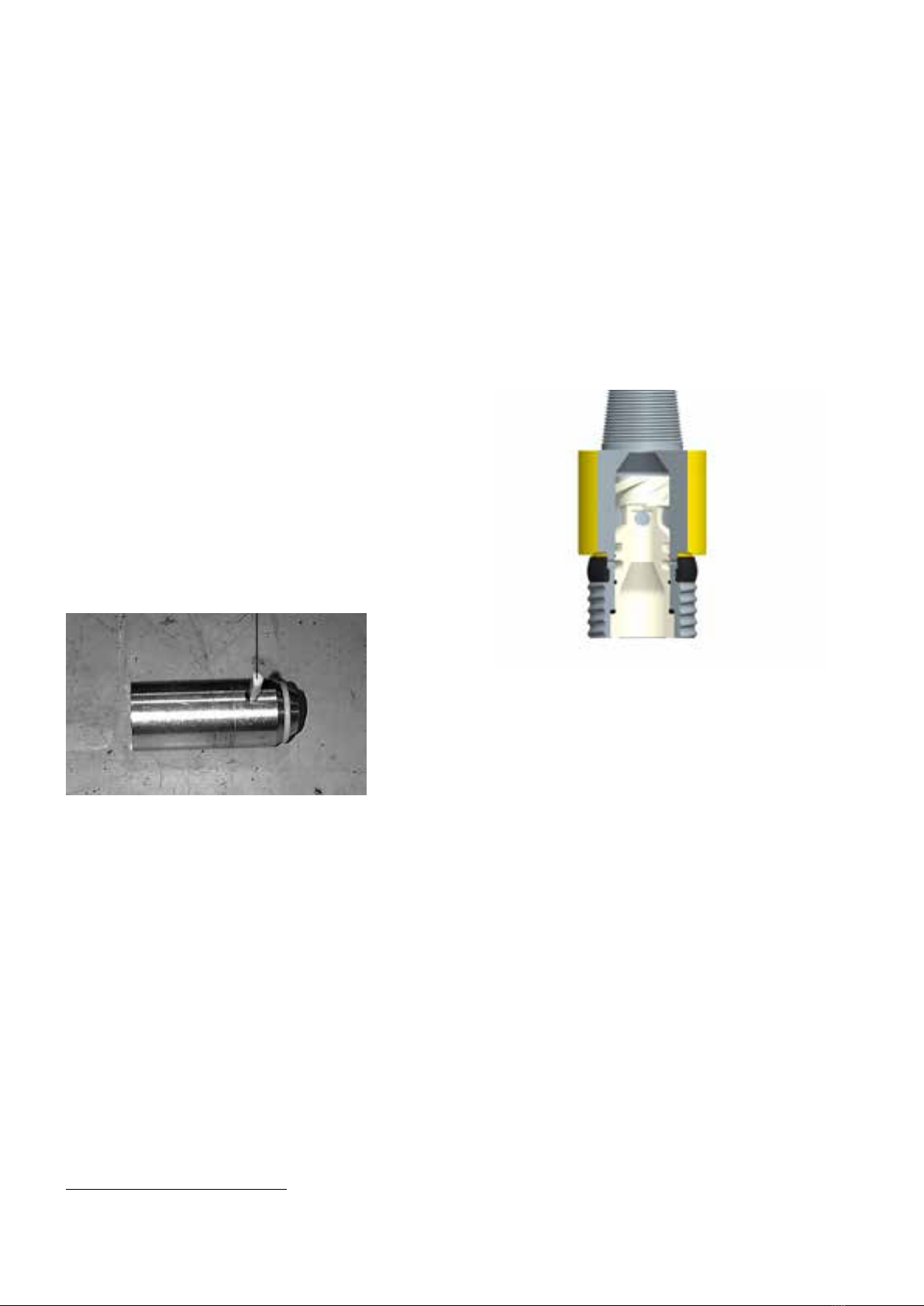
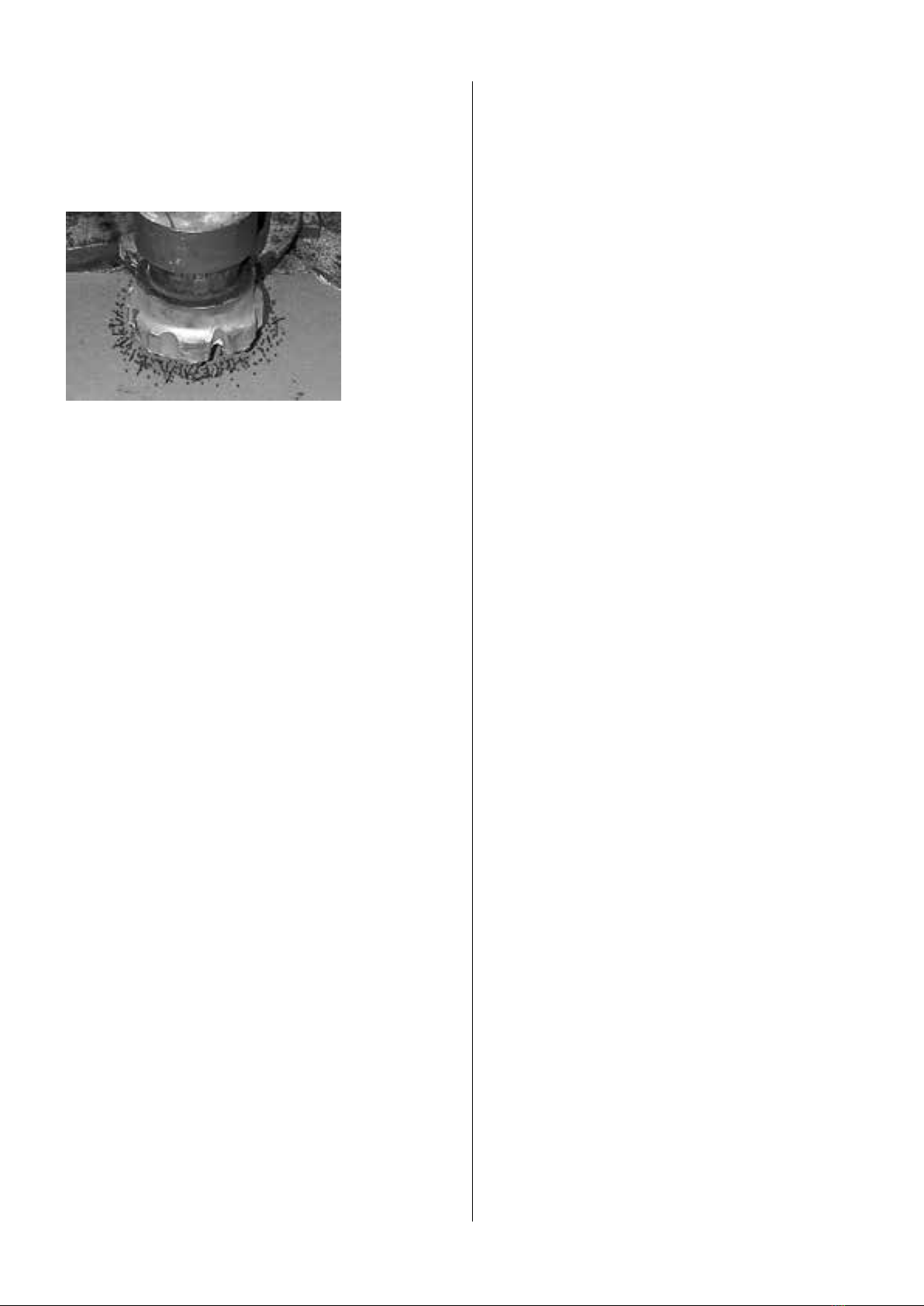
The picture following shows an example of the marks left on a
drill pipe when using chalk to mark the advance of the drill.
Another method for setting rotation speed involves observing
the wear flat developed on the gage (outer) carbide. The wear
flat on the should be directly on the top of the inserts. A flat
which is on the leading edge of carbide (side facing the direction
of rotation) indicates rotation speed is too slow. Conversely,
rotating too fast will cause rapid wear of the bit and the wear flat
will be on the trailing edge of the carbide.
Note: Due to the higher penetration rate of QLX drills over
conventional valveless drills, rotation speed will normally need
to be increased in proportion to the increase in drilling speed.
View showing wear flat on leading edge - indicates rotation too
slow. Note that carbide failure was caused by the leading edge
wear flat.
Feed force (hold down and hold back)
The force required to feed a percussive tool properly is directly
proportional to the level of output power.
As a rule of thumb, DTH hammers need to be fed with a force of
roughly 500 lb per inch (9 kg per mm) of hammer diameter when
operating at maximum power.
In many cases operators will simply adjust the feed pressure
until rotation pressure starts to pulse and then back off slightly
until rotation pressure becomes smooth. When a hole is first
started, if the weight of the starter rod or collars is not ufficient
to feed the drill then pull down will be needed. As the hole is
advanced and more weight is added to the drill string, the level
of pull down will need to be decreased. Eventually, the weight of
the string may exceed the proper feed force and the feed system
will need to be shifted to a pull-back mode.
When drilling through varying conditions such as hard and soft
or voided material, every effort should be made to keep the drill
fed properly. A loose running DTH hammer can cause damage to
the hammer and bit in a short period of time. The feed system of
a drilling rig should have a sufficiently fast response so the DTH
hammer can ´catch up´ with the bit when a void or soft seam is
encountered.
As with rotation speed, QLX drills will typically need to be fed
harder due to their higher output power level over valveless
drills. Adjust RPM to give 1/2’’ to 3/4 ‘‘ (13 to 19 mm).
Rotation Torque
As a general rule of thumb, you should apply roughly 500 foot/
pounds (27 newton/meter) of torque for each inch of bit
diameter.
Example: 6 inch diameter bit X 500 ft/ pounds =
3000 ft/pounds of rotation torque
It´s equally important to avoid feeding too hard through voided
and fractured material. The piston in a DTH hammer operates
within the casing with a clearance of about .003 in. (.076 mm) on
each side. While the casing appears very strong and stiff, it does
not take much sideways pressure to distort the casing enough to
cause interference with the piston as it reciprocates. If the casing
is overfed through voided ground it is likely that deflection of the
casing will occur. Frictional cracks will develop on the surface of
the piston if the piston rubs hard enough against the wall of the
casing while being distorted. These small frictional cracks can
eventually grow and break the piston.
Feed force should be reduced when drilling through voided,
unconsolidated or fractured ground to avoid twisting or
distorting the hammer casing.
Hole cleaning, flushing and dust suppression
As stated previously, the importance of good hole cleaning
cannot be over emphasized. A hole which is not cleaned
effectively will cause reduced production (penetration rate),
decreased bit and accessory life and could ultimately increase
the risk of losing the drill and string in the hole.
Deep Hole drilling requires that you maintain a proper annulus
around the casing, to reduce backpressure and maintain
performance.
Dry drilling
The most effective means for hole cleaning is drilling dry.
Cuttings are normally lifted and cleaned from the hole very
efficiently. Imagine blowing, or sweeping, dust or dirt from a
floor when the floor is dry and wet....which is more effective?
The same principle holds true for cleaning cuttings from a hole.
Wet drilling
Water injection is required in many applications for dust
suppression or hole cleaning. Water injection rates for dust
suppression only are usually less than 1 gpm (3.8 lpm) and
just sufficient to moisten fine dust. It is usually common to use
minimal water injection for dust suppression in shallow blasthole
applications where water intrusion into the hole is not a problem.
Heavier volumes of water injection are usually required in water
well and deep-hole applications where a number of factors come
into play;
• Water intrusion into the hole can develop mud rings where
dry cuttings meet a seam of water entering the hole. Mud
rings develop where dry cuttings stick to the wall of the
hole when they hit the moist area. Water injection is needed
to keep the hole wet enough to prevent these mud rings
from developing. Fluid injection rates can vary from 2 - 15
gpm (7.57 - 56.775 lpm) depending of the hole size, rate of
penetration and the type of material being drilled.
• Some materials such as those which drill fast or contain clay

11
can sometimes require very heavy levels of water injection.
These applications are unique in that they can either be
drilled totally dry or totally wet....not in between. Marginal
fluid injection results in making a tacky mud which sticks to
the drill rods and hole wall and hinders hole cleaning. The
correct level of fluid injection thins the paste so it will be
cleared from the hole.
Bit changing
Removing the drill bit
Bit removal can be one of the most dangerous and frustrating
tasks associated with the drilling operation. However, with the
proper tools and techniques it should require no more than a few
minutes to remove a bit. The following lists pointers which will
be beneficial in helping you remove a bit quickly, safely and with
reduced risk to damaging DTH hammer parts and components:
1. Use sharp tong jaws. Worn or rolled over tong jaws increase
the jaw pressure and make the wrench more prone to
damaging the hammer case. Many Atlas Copco hammer cases
are case hardened which means sharp jaws are needed to grip
through the hardened case.
2. Grip the casing in the proper location. Gripping over the
threads can make thread loosening extremely difficult.
Example; as the wrench tightens it exerts an inward force
which can pinch the threads if they are under the wrench jaw.
This only increases the torque needed to uncouple the thread.
Also, do not grip the casing in an area where the bore is not
supported by either the piston or bearing. Gripping over an
unsupported area can distort the bore. The following table
and figure shows the recommended locations for wrenches.
CHAIN WRENCH POSITIONS
Hammer model Minimum distance
from chuck to
lower jaw
Maximum dis-
tance from chuck
to upper jaw
QLX 35 4.7 in. (119 mm) 8.5 in. (216 mm)
QLX 40 5.5 in. (139 mm) 13.5 in. (342 mm)
QLX 50/55 6.5 in. (165 mm) 12.5 in.
(318 mm)
QLX 60/65 6.5 in. (165 mm) 13 in. (330 mm)
QLX 100 9 in. (228 mm) 20 in. (508 mm)
Top of jaw
Maximum
distance
Bottom
of jaw
Minimum
distance
QLX 35 minimum distance from bottom of chuck to bottom of
jaw / 4.7 in. (119 mm). Maximum distance from bottom of chuck
to top of jaw / 8.5 in. (216 mm)
QLX 40 minimum distance from from bottom of chuck to bottom
of jaw / 5.5 in. (139 mm) Maximum distance from bottom of
chuck to top of jaw / 13.5 in. (342 mm)
QLX 50/55 minimum distance from bottom of chuck to bottom of
jaw / 6.5 in. (165 mm). Maximum distance from bottom of chuck
to top of jaw / 12.5 in. (318 mm)
QLX 60/65 minimum distance from bottom of chuck to bottom of
jaw / 6.5 in. (165 mm). Maximum distance from bottom of chuck
to top of jaw / 13 in. (330 mm)
QLX 100 minimum distance from bottom of chuck to bottom of
jaw / 9 in. (228 mm). Maximum distance from bottom of chuck to
top of jaw / 20 in. (508 mm)
3. Insure the bit fits properly within the bit basket. An improper
fit may result in the bit slipping from the basket.
4. Never weld or hammer on the casing to loosen it. Many
casings are case hardened for extended service life. The hard
casing surface can be cracked by welding or impacting with a
sledge hammer. If a chuck or backhead is difficult to loosen,
repeatedly tapping the casing at the thread location with a
brass bar or hammer while torque is applied may help loosen
the joint.
Insure chain wrenches or tongs are rated for
the torque applied. The flying parts of chain
wrenches can cause injury or death when they
break!
WARNING
Removing the bit with percussion only
If a chuck is difficult to loosen it´s sometimes helpful to use low-
pressure percussion assisted with reverse rotation to free the
thread. The following lists the process and cautionary
notes:
Wear eye protection as the hammer will be cycling above
ground. Insure that all drill string joints are tight. Watch
other string Joints to insure they do not loosen before
the chuck. If they do loosen, stop the process
CAUTION
Process instructions
1. Place a piece of relatively hard polyurethane or conveyor
belting in the bit break-out basket to absorb shock.
2. Remove all drill pipe so only the DTH hammer and required
adapters are attached to the rotary head.
3. Bring the drill in contact with the bit basket with a relatively
light feed.
4. Bring the hammer pressure up to roughly 150 psig (10.3 bar).
5. See if the joint has loosened on its own after about 10 seconds
of cycling.
6. If the joint has not loosened, ´Bump´ the rotation in reverse at a
slow speed while the drill cycles until the joint has loosened.
7. Stop as soon as the chuck loosens, grease and air will be
noticed coming from the loosened joint.

12
MAINTENANCE AND
REPAIR
Follow instructions
Along with correct operational technique; proper and timely
service and repair of a DTH hammer can extent component life
and reduce operational expenses considerably. The sections
following describe how to disassemble, inspect, repair and
reassemble all QLX hammers.
Depending on the degree to which you plan on servicing a DTH
hammer, a number of tools are required. The following lists the
tools needed for a complete overhaul of all QLX hammers. A
stand is required for holding the DTH hammer and it is presumed
that backhead and chuck threads have been loosened. Complete
overhaul includes measuring and inspecting all clearances at
seal locations and other wear points.
DTH hammer service
In most cases a DTH hammer will only require servicing when
the casing wears out or when performance deteriorates due
to internal parts wear. The level of inspection can obviously
be much less if the casing only needs replacement. If the DTH
hammer has lost performance a more detailed inspection will be
required.
Disassembly
The following disassembly procedure starts with the
presumption that the chuck and backhead threads have
been loosened. While the disassembly process is similar for all
QLX drills there are slight distinctions from one model to another
that will be noted.
Note: The QLX piston can be removed from either end of the drill.
QLX 40 piston can ONLY be removed from chuck end.
1. Mark the casing so you can note which end is the backhead
side and which is the chuck end. Once the hammer has been
disassembled it´s hard to tell which end is which.
Note: On QLX 50/55 and QLX 60/65, the casing is reversable
2. Loosen the chuck along with bit and retaining rings and
remove from casing.
3. Remove retaining rings and o-ring from bit shank.
4. Remove the chuck from the bit.
5. Remove the backhead from the other end of the casing.
The compression cone, check seal, guide, and valve assembly
will come out with the backhead. If the backhead is removed
before unseating the compression cone use one of the
following methods for removing the stuck part:
NOTE: QLX 40 does not have compression cone.
For QLX 50/55 and QLX 60/65 the distributor/compression cone
valve assy and guide plug will come out as an assembly. The
guide plug in the distributor is held in place by the detent kit.
The air select (guide plug) does not need to be
removed unless the air select is not adjusting
into select position. In this case remove plunger,
spring and plug and replace with new detent kit.
• If the compression cone remains in the hammer when
the backhead is removed it will be held under very
high load by the spring action of the cylinder. when
released, the compression cone will be forcefully
ejected from the casing. Use caution when removing
the cone to avoid personal injury. Do not stand or
place any part of the body in front of the casing
opening when loosening the compression cone.
• If the compression cone is stuck in the cylinder, it
will be difficult to unscrew from the casing after the
joint is initially broken loose. The check seal is often
dislodged from its normal location as well.
• If this happens, tap the casing lightly with a soft faced
hammer or brass bar about 1/4 to 1/3 the casing length
from the backhead end of the casing until you hear a
loud snap which indicates the cone has unseated.
WARNING
a. Carefully stand the casing on a flat, level surface, backhead
end down. Use a soft faced hamer or brass bar to tap the
casing lightly at the location of the top of the cylinder. The
compression cone will be released.
b. Partially reinstall the backhead or chuck to block the
compression cone when it releases with the hammer lying
horizontally, use a soft faced hammer or brass bar to tap the
casing lightly at the location of the top of the cylinder. The
compression cone will be released.
6. With a brass bar, push the piston upward from chuck end
towards backhead end until it contacts the cylinder, then strike
the end of the piston firmly with the bar to drive the cylinder
out of the retention groove in the casing. Once dislodged from
the retention groove, continue to tap the piston until the top
end of the cylinder comes out of the casing. The cylinder can
now be removed by hand.
Note: QLX 40 cylinder is NOT removable
7. The piston can be removed from the backhead end of the
casing by pushing it with a brass bar until it can be extracted
by hand.
Note: QLX 40 piston ONLY from chuck end once bearing and
bearing o-ring is removed
8. Remove the bit bearing from the hammer. The bearing can
sometimes be removed by hand, but often will require the use
of a bearing puller. When using a bearing puller, be sure it is
in contact with the bearing and not the bearing retainer. The
bearing can also be removed by inserting the piston (small
end first) into the backhead end of the casing and tapping the
piston with a brass bar to drive the bearing out of the casing.
Note: QLX 40 piston can not be used to remove bearing
9. Remove the bearing retainer ring from the casing. With the
piston in normal position (striking end facing the chuck end
of the casing) drive the bearing retainer ring out of its groove
using the brass bar. It may be easier to do this with the casing
in a vertical position (chuck end down).Be careful to avoid
striking the lip at the piston ID to avoid chipping the piston. It
may be helpful to place a block of wood or other soft material
on top of the piston to cushion against damage.

13
Assembly
1. Lubricate inside of casing and cylinder. Lubricate outside of
cylinder. Place cylinder inside casing and drive into place.
Use of cylinder assy tool or old valve will be helpfull or use of
brass bar. Cylinder will snap when locked into place. Some
movement ( ¼’’ – ½’’ ) is normal. Push cylinder forward.
NOTE: QLX 40 cylinder is pre-shrunk into casing
Assembly tool # 52341229 is available for QLX 50/55 and
assembly tool # 52341286 is available for QLX 60/65.
2. Reassemble distributor with new o-rings (compression cone)
and valve assy. Guide plug still should be in place. Check for
position by rotating clockwise and counter closewise. See
previous note for Airselect setting, keeping in mind not to
rotate below setting #1 or above #5.
3. Place check valve and spring into distrubtor bore.
4. With backhead lying horizontal, lubricate backhead ID and
distrubtor OD. Place distributor assemble inside backhead.
5. Holding on to distrubtor and backhead, place complete
assemble into casing and screw together (grease threads).
6. Once backhead o-ring is compressed into casing, there should
be a minimul gap. This gap should be close when torquing
joints together. SEE PREVIOUS PAGES FOR TORQUE.
7. Moving to chuck end. Lubricate inside casing and piston. Side
piston in by hand, should be free.
8. Install bearing retaining ring.
9. Lubricate bit bearing and install.
10. Place chuck over bit splines along with bit retaining rings and
screw into casing, grease threads and splines.
Disassembly QLX 100
The following disassembly procedure starts with the resumption
that the chuck and backhead threads have been loosened. While
the disassembly process is similar for all DTH hammers, there
are slight distinctions from one model to another that will be
noted.
It’s important to note that the piston can only be removed
from the chuck end of the drill.
1. The QLX100 casing is not reversible. To ensure that the
hammer is assembled properly, mark the casing so you can
note which end is the backhead side and which is the chuck
side.
2. Loosen the chuck along with bit and retaining rings and
remove from casing.
3. Remove retaining rings and o-ring from the shank.
4. Remove the chuck from the bit.
5. Using a screwdriver as a tool to free one end, remove the
bearing retaining ring.
6. Pull the bit bearing from the hammer casing. Depending on
the degree of rust or dryness in this area, a bearing puller may
be needed for removal.
7. After removing the bit bearing, the bit bearing stop ring can be
removed by hand.
8. Slide the piston out of the drill, being careful to support its
weight when it’s no longer supported by the casing.
9. Moving to the opposite end of the drill, remove the backhead.
Unscrewing the backhead. Use a lifting device or strap to support
the backhead.
10. Remove the check valve and spring.
11. Remove the Belleville spring.
12. Remove the upper end assembly consisting of the valve cap,
valve, distributor, and cylinder. This can be accomplished in
two ways:
a. Insert a brass bar from the chuck end of the drill and tap or
push the complete assembly out of the backhead end.
b. Pull the assembly out using the two provided 5/8-11 UNC
threaded holes in the valve cap.
Removing the upper end assembly.
13. Remove the valve cap from the distributor. Use a brass bar to
knock the valve cap off of the distributor stem.
14. Separate the distributor and cylinder. A preferred method is
to take the cylinder and distributor assembly and fit it over the
small diameter end of the piston, resting vertically on a table
or the floor. Grasp the outside surface of the cylinder and raise
the assembly up, impacting it down onto the piston. This will
free the cylinder. Be careful not to get fingers caught in the
cylinder while driving it up and down.
15.Also, can be seperated by laying distributor and cylinder on
its side, from open end of cylinder use brass bar and drive
against distributor guide.

14
Assembly QLX 100
The DTH hammer assembly process is identical to the
disassembly process yet in reverse. The following guidelines
should be used:
• All parts should be clean and free of grit dirt and other foreign
material.
• All nicks and burrs on parts should have been removed.
• All parts should be coated with rock drill oil and preferably the
same type to be used on the drilling rig.
• All damaged o-rings should have been replaced if. All seals
should be oiled or greased to avoid cutting or tearing.
• If corrosion is common it may be useful to spray the threads
on the casing with a corrosion protector such as LPS Hardcoat
or equivalent. Make sure the threads are clean and dry and
sufficient drying time is allowed.
1. Lubricate the valve seals and install the valve in the valve
cap. Ensure that the valve cap/distributor o-ring is installed in
the valve cap and that the distributor plugs are installed in the
distributor.
Installing the valve in the valve cap.
2. Lower the valve cap/valve assembly over the distributor stem.
Installing the valve cap.
3. Place the valve cap/distributor assembly over the cylinder. Use
a brass bar to drive the assembly together until all faces mate
together.
Installing the distributor in cylinder.
4. The assembly can then be coated with rock drill oil and
installed in the backhead end of the hammer.
Installing the assembly in the hammer.
5. Lubricate and install the Belleville spring, check valve spring,
and check valve. Ensure that the spring is installed concave up.
Installing check valve.
6. Install backhead o-ring, apply thread grease, and install
backhead.
Installing backhead.
7. Moving to the chuck end of the hammer, install the piston. A
lifting device or strap should be used to help support the weight
of the part.
Lubrication and installation of the piston.

15
8. Install the bearing stop ring.
Ring installed.
9. Lubricate and install the bit bearing.
Bit bearing installed.
10. Install the bearing retaining ring. Start at one end of the cord
and force it into the groove below the bearing all the way around.
11.Place the chuck, drive pins, and retrieval sleeve (if equipped)
over the bit. Install bit retaining rings with o-ring. Lubricate the
exhaust tube with rock drill oil and the chuck threads with thread
grease. Install the assembly in the hammer.
DTH hammer inspection
When a QLX hammer is disassembled, all parts should be
inspected to determine which, if any require replacement, repair,
or reversal. Refer to the specifications to find the appropriate
discard point clearances. The discard point clearances listed
represent an increase in clearance of 50% over the maximum as-
new clearance. In some applications this clearance increase may
represent too much performance loss, and in other applications
additional wear (performance loss) may be acceptable.
Deterioration in drill performance is caused by the increase in
clearance between parts. It is more cost effective to replace the
part that decreases clearance the most at the lowest cost. The
chart in Section 5 tabulates the new diameters from which the
wear on each part can be assessed.
1. Casing outside diameter should be measured roughly 2 to 3 in.
(51 to 76 mm) from the end of the chuck end. Refer to the casing
reverse and discard dimensions to determine if the asing should
be replaced or reversed. Refer to the assembly instructions for
the proper casing reversal procedure.
• It is suggested that the chuck be replaced when the casing is
reversed.
2. Inspect the chuck
• Check the overall length of the chuck shoulder against the
specifications. A short chuck shoulder can cause cycling
problems, difficulty handling water, and rough operation.
• Check the chuck inside diameter. Replace if worn beyond
recommended limits.
• The chuck should be replaced if spline wear is heavy or
uneven.
• The chuck should be replaced if its minimum outside diam-
eter is less that the casing discard diameter.
3. Inspect the backhead
• Check the condition of the connection thread. Replace the
backhead if the threads are torn,galled or damaged, or if the
make-up shoulder is damaged or worn.
• Check the condition of the internal connection thread. Minor
damage can be repaired by filing or lightly grinding the
damaged area. Replace the backhead if the threads are badly
worn, damaged or cracked.
• Polish or clean valve stem of debris/corrosion.
4. Inspect the backhead o-ring and replace if damaged.
THREAD SHOULDER O-RING
CONDITION CONDITION CONDITION
5. QLX 35: Inspect the check seal. Replace if cracked, torn, or if
the seal is brittle. Check valve O-ring for all other.
6. Inspect the guide for wear, scoring, or galling. Replace if worn
beyond tabulated limits. A wear pattern on one side of the guide
can indicate misalignment in the drill. If this condition is ob-
served, check other parts carefully to identify the source of the
misalignment.

16
Note for QLX 40: If the valve assembly (item7) is replaced
with new o-rings, the valve should be installed in the closed
position (valve seated against cylinder).This will insure that the
hammer will start without incident. New o-rings may require a
break-in period of 100 feet (30 meters).
7. Inspect the valve assembly for seal interference and damage.
The valve seals should have interference with the distributor
guide and backhead, but still move freely.The valve sealing
surfaces should be free of nicks, and burrs. Also inspect for
valve seal wear on the grooves.
8. Inspect the bearing bore just above the internal flutes for
wear using a telescopic bore gauge and micrometer. Replace
the bearing if the net clearance between the bit and bearing
is beyond the tabulated discard point. Replace the o-ring if it is
worn or damaged.
9. Inspect the piston in the locations noted below.The piston
usually wears faster than its mating parts, so it is likely piston
wear will affect clearances the most. Record the dimensions for
comparison to mating parts (cylinder and casing) to determine
which part offers the most economical replacement cost.
• Measure the tail outside
diameter as shown.
• Measure the tail bore, inspect for seal damage. If the
seal requires replacement, remove by prying it out with a
screwdriver. Install the replacement seal by working it into
the groove by hand as much as possible, then seating it by
lightly tapping with a soft-faced hammer.
• Measure the large piston diam-
eter in the location shown.
Note:This is the most critical wear
point on the drill, as it has the great-
est influence on performance.
Always recommended to change tail
seal when servicing hammer.
10. Carefully remove any sharp edges, burrs, or nicks that have
developed on the piston using a hand grinder or emery cloth.
DO NOT OVERHEATTHE PISTON..... IT WILL CRACK IF OVER-
HEATED! If the piston striking face is heavily cavitated or pitted
use a ceramic facing tool or well-cooled grinder to dress the
face. A maximum of .060 in. (1.52 mm) can be removed from the
piston face.
11. If the casing does not require replacement due to outside
diameter wear, measure the bore diameter using a telescopic
bore gage and micrometer as shown. Record the measurement
for later reference. Polish any rough or galled spots in the casing
bore with emery cloth. Larger areas of damage can be smoothed
out using a hand grinder with flap wheel. Be careful not to
remove too much material from the bore to avoid degradation of
hammer performance.
Measure at this
location (1/2” past
long undercut)
12. Inspect the cylinder for cracks or
damage.
Inspect the valve seat for damage
and wear.
Measure the diameter of the bore and
record for later reference. Scored or
galled areas of the bore can be polished
with emery cloth.
13. Determine the following clearances from the dimensions
recorded.
• Bit to bit bearing
• Piston to casing
• Piston to cylinder
• Piston tail bore seal to guide
14. Referring to the as-new dimensions and recommended
replacement clearances in Section 5, determine which parts have
suffered the most wear. Replace the part(s) needed to bring the
clearances back to specification.The chart below may be useful
for recording and determining which clearances require service.

17
DTH HAMMER CLEARANCE WORKSHEET
Dimensions Measured
dimension
As new
diameter
from table
Actual
wear
Measured
clearance
Discard
clearance
from table
Piston to Casing
Large piston OD
Casing ID
Piston to cylinder
Small piston OD
Cylinder ID
Piston to guide
Piston tail ID
Guide OD
Bit to bearing
Bit bearing ID
New bit tail OD
ID A B C D
2A-1A
E
1
2
1B-1A
2A-2B
4A-3A
3
4
3B-3A
4A-4B
5A-6A
5
6
5A-5B
5B-5A
7A- 8A
8
77A-7B
8B-8A
TROUBLESHOOTING GUIDE
The majority of DTH hammer operating problems can be traced to improper operation.These troubleshooting charts will help you by sug-
gesting a probable cause and a recommended remedy.
PROBLEM CAUSE REMEDY
Rough-erratic
operation
1. Too much water injection
2. Chuck has worn too much
3. Rotation speed too slow
4. Feed too hard
5. Worn/Broken Tail seal.
Bore Seal
6. Worn/leaking valve seal
7. Worn bit bearing
8. Worn piston exhaust tube
9. Incorrect Airselect setting
1. Reduce level of water injection.
2. Inspect chuck length for correct body length. A short chuck will restrict air
needed to return piston. Note that body length is the distance from the shoulder
which contacts the casing to
the shoulder that contacts the bit.
3. Increase rotation speed to get no more than 1/2 in. (12.7 mm) advance per
revolution. Watch flat on carbide; if it´s on the leading edge of the insert rotation´s
too slow.
4. Set feed pressure (decrease holddown or increase holdback) just until pulsation
in rotation pressure falls and pressure is steady.
5. Replace seal.
6. Check for axial wear of outside valve seal groove. Replace valve assembly if
groove has worn more than .06´ (1.5 mm)
7. Replace bit bearing. Leakage past bit bearing may cause piston to lack upstroke
force making cycle erratic.
8. Inspect piston bore and exhaust tube vs. bore or exhaust tube. specification.
Replace if needed. Leakage past this clearance can reduce piston upstroke force
making cycle erratic.
9. Change setting to next higher flow position.
Low
penetration/
high pressure
1. Worn/leaking valve seal
2. Chuck has worn too much
3. Too much water injection
4. Contamination (rubber
hose, etc.) jammed in
hammer
1. Check for axial wear of outside valve seal groove. Replace valve assembly if
groove has worn more than .06 in. (1.524 mm).
2. Inspect chuck length for correct body length. A short chuck will restrict air
needed to return piston.
3. Reduce level of water injection.
4. Remove obstruction which may be holding the valve closed or restricting the
air flow.

18
PROBLEM CAUSE REMEDY
Low
penetration/
high pressure
5. Exhaust tube projection
too long
6. Valve action impeded
7. Worn Tail Seal
5. Check projection vs. specifications repair tube.
6. Check nose of backhead for corrosion other deposits that can interfere with the
smooth cycling of the valve. Remove deposits if present.
7. Replace Tail Seal.
Low
penetration/
low pressure
1. Lack of oil
2. Worn drill clearances
3. Damaged valve seat
4. Incorrect Airselect setting
1. Insure lubricator is working and hammer is getting coated
with oil. Check bit blow ports for oil film.
2a. Inspect piston for wear particularly on large diameter just beneath scallops.
This is the most sensitive diameter. Check other diameters; tail bore seal and tail
diameter for wear. Compare all to specification.
2b. Inspect guide diameter for wear. Compare with
specification and replace if necessary.
2c. Check cylinder bore for wear. Compare to
specification and replace if necessary.
2d. Check casing bore for wear. Compare to
specification and reverse or replace if necessary.
2e. Check bearing bore for wear. Compare to
specification and replace if necessary.
3. Inspect valve seat surface for damage or wear
which could cause leakage. Replace valve is suspect.
4. Readjust Airselect.
Drill running
off bottom
1. Worn piston
2. Excessive water injection
3. Debris (cuttings, mud)
between chuck and bit spline
1. Inspect large diameter of piston for wear. Leakage past the large diameter can
cause the piston to cycle when off bottom.
2. Try reducing water injection level. Water inhibits the air venting process which
is needed to shut the hammer off.
3. Clear debris.
Chuck hard to
loosen
1. Poor gripping
2. Conditions
1a. Don´t grip over threads.
1b. Insure tong jaws are sharp.
2. Try using breakout washer.
Compressor
unloading
1. Incorrect Airselect setting
2. Excessive water injection
3. Mud Rings
1. Correct Airselect setting.
2. Reduce water injection rate.
3. Clear mud ring. Increase water injection. Consider
adding foam
.
Hammer
won’t start
1. Mud or dirt in hammer
2. Broken exhaust tube
3. Broken internal parts
1. Disassemble, clean, inspect and repair hammer. Check for
proper function of check seal.
2. Replace tube. Inspect Bearing and Chuck.
3. Replace broken parts.
Component
failures
1. Piston cracked through 1a. Lack of lubrication could cause frictional cracks in large diameter. Check
lubricator and insure oil film is developed on
bit blow holes.
1b. Wrenching over wrong location distorts casing and causes frictional rubbing
with piston. Apply tong wrench pressure in correct location.
1c. Fighting or getting stuck in hole heats and distorts casing bore causing
frictional heat and cracks on piston. Flood tool with water when stuck.
1d. Collaring on an angle or feeding hard through voided, faulted or broken
ground can cause casing to distort and rub piston causing cracks. Use light feed
when going through tough conditions.

19
PROBLEM CAUSE REMEDY
Component
failures
2. Piston struck end cupping
3. Cracked casing
4. Rolled over chuck
5. Cracked backhead-body
6. Cracked backhead
2a. Usually a sign of underfeeding. Increase feed or breaking. until rotation
pressure pulses and then back down till smooth.
2b. Cavitation from excess water injection can cause small pits in piston face.
These pits turn into cracks. Avoid excessive water injection.
3a. Hammering, welding and wrenching in wrong location can fail casings; avoid
these practices and use sharp tong jaws to loosen connections.
3b. Corrosion from internal undercuts and threads;
use good quality (neutral pH) water and flush with oil when finished drilling.
If possible, coat threaded areas undercuts and bore of casing with corrosion
protector such as LPS Hardcoat.
3c. Look for beat in chuck which could allow the piston to stroke far enough to
contact air distributor and overstress the casing. Replace chuck if worn more than
specification.
3d. Look for leaking or loose fitting large diameter valve seal which could make
piston stroke too far and contact distributor. Replace the valve assembly.
3e. Casing has worn beyond discard point. Measure casing OD about 2 in. (50.8
mm) from chuck end. Compare to specification and replace if needed.
3f. Backhead or chuck thread loose. Be sure threaded joints are tight. Do not
reverse rotate or allow hammer to cycle without rotation.
4. Underfeeding can cause the bit to rebound into chuck shoulder. This will
generate a rolled up edge. Increase feed force.
5. Fighting from hole and pulling backhead through caved-in materials creates
frictional heat. Rotate slowly and/or flood with water when stuck.
6. Look for evidence of connection moving on threaded
shoulders. Connection shoulder may be worn allowing movement. Replace/repair
adapter sub or rod.
Breaking
exhaust tubes
1. Erosion
2. Damage
3. Bit tube bore small
1a. Water jetting erodes base of bit tube at striking surface. Reduce level of water
injection.
1b. Contaminants in water mix and cause abrasive blast at base of exhaust tube.
Use clean water.
2a. Damaging tubes when changing bits. Be careful to thread casing onto chuck
while vertical and in alignment.
2b. Use care when transporting bits to avoid damage to tube.
Keep bit in box until needed.
3. The tube bore of a bit can become deformed and pinch the tube. Look for a
rolled over edge or deformation at the top of the bit bore. Remove by grinding
away lip.
Chuck
loosening in
hole
1. Running loose
2. Improper make up torque
1a. Refer to proper feed settings (Section 1)
1b. Avoid feathering feed in loose ground or at end of rod.
2. Tong chuck tight before drilling.
Cylinder
Tangs broken
1. Tail Seal failure
2. Corrosion
1. Replace Tail Seal
2a. Be sure hammer parts have a good coating of oil.
2b. Clean and oil hammer after drilling with foam.
2c. Use non-acidic injection water.

20
Minimum guidelines
for mounting specifications
Torque:
Roughly 500 ft-lb per inch (27 N-m per mm) maximum of bit.
Speed:
10 to 90 rpm
Hold down force:
500 lb per inch (9 kg per mm) of hammer maximum
(i.e. TD60 needs 3000 lb (1360.8 kg)
Hold back force:
Dependent on hole depth and string weight.
Must be capable of maintaining 500 lb per inch (226.8 kg per mm) at
depth.
Operating pressure:
500 psi (34.4 bar) maximum
Volume:
150 - 200 scfm per inch (.165 - .22 m3/min per mm) of hammer
diameter.
Lubrication:
1/3 pint (.16 l) per hour per 100 scfm (2.8 m3/min)
Minimum requirements for
compressor capacity and pressure
The pressure and production developed by a DTH hammer will be
related to the air flow passing through the drill. The pressure and
performance of a DTH hammer is related to the SCFM delivered
by the compressor. To determine what pressure a DTH hammer
will carry (without fluid injection and well oiled) you need to take
into account the actual SCFM (or mass flow) of air delivered by the
compressor. Compressors are rated in ACFM which only equals
SCFM at standard conditions of sea level and 60 F (16 C) inlet
temperature. As the inlet air density either increases or decreases
due to temperature and altitude changes, the SCFM delivery of a
compressor will change. The pressure and performance of a DTH
hammer are related to the SCFM delivered by the compressor.
Figures 4 and 5 show the relationship of pressure and flow for all QLX
hammers running oiled with no water injection in a shallow hole.
The Figure 1 shows compressor correction factors for typical oil
flooded screw compressors. The rated delivery of a compressor must
be multiplied by the correction factor to determine delivery in SCFM.
The flow in SCFM should be used for determining the pressure the
drill will hold referring to Figure 1.
Altitude - feet (meters) sea level 0 (0) 2,000 (609.6) 4,000 (1219.2) 6,000 (1828) 8,000 (2438.4) 10,000 (3048)
Atmospheric pressure
PSIA (mm Hg) 14.70 (760.2) 13.66 (706.4) 12.68 (655.7) 11.77 (608.7) 10.91 (564.2) 10.10 (522.3)
Temperature F (C)
0 (-18) 1.07 0.99 0.92 0.86 0.79 0.74
20 (-7) 1.05 0.97 0.90 0.84 0.78 0.72
40 (4) 1.02 0.95 0.88 0.82 0.76 0.70
60 (16) 1.00 0.93 0.86 0.80 0.74 0.69
80 (27) 0.98 0.91 0.85 0.78 0.73 0.67
100 (38) 0.96 0.89 0.83 0.77 0.71 0.66
120 (49) 0.94 0.88 0.81 0.76 0.70 0.65
Super-tac rock drill oil part numbers (not available for the EU market)
1 Gallon 5 Gallon 55 Gallon 300 Gallon ISO Grade Viscosity Viscosity Pour Point Flash point Emulsion
Grade 3,8 Lit 18,9 Lit 207 Lit 1136 Lit (reference) (Cst @ 40°C) Index (typ) Max °F (°C) Min °F (°C) Min t 35 ml.
Test reference-ASTM D2270 D97 D92 D1401
Test reference - ISO 2909 3104 2592 3488
Light 52334174 52333192 52333200 52343225 100 90-110 124 -16 (-26) 460 (237) >60
Medium 52334182 52333218 52333226 52343233 220 198-242 121 0 (17) 457 (236) >60
Heavy 52334190 52333234 52333242 52323241 460 380-430 94 10 (-12) 455 (235) >60
Extra heavy 52334208 52333259 52333267 52343258 1000 1078 95 34 (1) 480 (249) >60
Rock drill oil specifications
Viscosity:
SUS at 100°F (38°C)
SUS at 210°F (99°C)
cST at 104°F (40°C)
cST at 212°F (100°C)
Pour Point, °F (°C) max.
Flash Point, °F (°C) min.
Viscosity Index, min.
Steam Emulsion No. min.
Consistency
Falex Load Test lbs (kg) [min]
Timken E.P. Test lbs (kg) [min]
ASTM-D2161
ASTM-D2161
ASTM-D445
ASTM-D445
ASTM-D97
ASTM-D92
ASTM-D2270
ASTM-1935-65
. . . . . . . . . . . . .
ASTM-D2670
ASTM-D2782
750 min.
85 min.
160 min.
16 min.
0°F
(-18°C)
450°F
(232°C)
90
1200
Stringy
2000 lbs
(907 kg)
30 lbs
(14 kg)
450 min.
65 min.
105 min.
11 min.
-10°F
(-23°C)
400°F
(204°C)
90
1200
Stringy
2000 lbs
(907 kg)
30 lbs
(14 kg)
Characteristic Test Below 20°F 20°F to 90°F Above 90°F
Procedure (-7°C) (-7°C to 32°C) (32°C)
175 min.
46 min.
37 min.
6 min.
-10°F
(-23°C)
370°F
(188°C)
90
1200
Stringy
2000 lbs
(907 kg)
30 lbs
(14 kg)
Figure 1. Altitude Correction
This manual suits for next models
8
Table of contents
Other Atlas Copco Rotary Hammer manuals