8
PAGE
Repair Instructions No.189.03/01
PHE 45 S
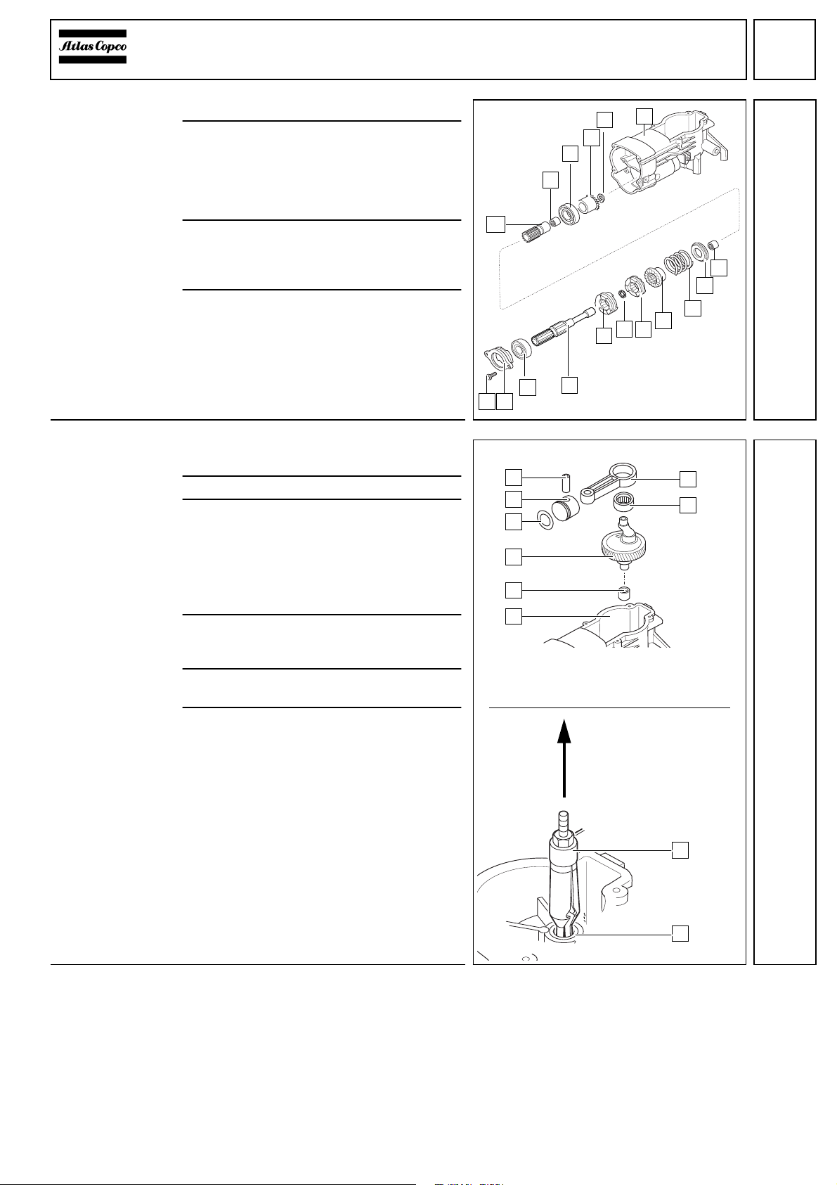
Assembling
the spindle 1Lightly grease the inner wall of the cylin-
der (4) and push it over the piston (O) (the
piston is illustrated on page 7, pos.5, ill. 1).
2Insert the cylinder (4) with the percussion
body (2), as well as the seal ring and the
O-ring (3) into the crankcase (5) and fas-
ten them with the four secured screws (1).
3Insert the O-ring (N), the snap die (M), the
disk(L), the O-ring (K)andthe disk (J) into
the spindle gear (G). Fit the disk (L) with
the phase facing the snap die. Mind the
right position!
4Push the spindle sleeve (7) with the
O-ring (6) over the spindle gear (G).
5Lock the spindle gear with the four
pins (H) using a magnet for support.
6Mountthe needlebearing (B),thedisks (C
and E), the cup springs (D) as well as the
needle bearing (F) in the bearing end
plate (A).
7Mount the locking ring (9) with aid of spe-
cial pliers.
8Insertthe sealring(8) into thebearing end
plate (A).
9Push the spindle sleeve (7) with the spin-
dle gear (G) into the bearing end plate (A).
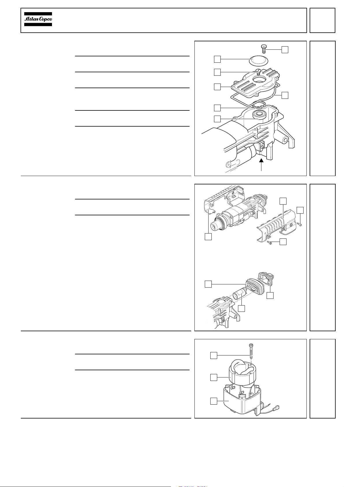
Mounting the
bearing end plate 1Push the backing flange (A) and the felt
washer (9) over the spindle sleeve.
2Fit the gasket (2) and the bearing end
plate (1) completely with the spindle
sleeve to the crankcase (8).
3Push the pressure spring (B) and the re-
taining plate (D) over the spindle sleeve
and depress them.
4☞Press in both locking levers (C) from
the side against resilience.
5Push the distance sleeve (6) and the
sleeve (7) over the spindle sleeve.
6Push the flange (E) over the spindle
sleeve (7) and fasten it tightly with the four
secured screws (F) (15 Nm).
7Push over the distance sleeve (4) and the
sleeve (5).
8Mount the cap (3).
D
1
6
54
3
2
7
8
9
A
B
C
EG
H
F
J
K
L
M
N
0
1
6
543
2
7
8
9A
BCDF
E
C