Splash Lab TSL.C.060 Maintenance and service guide

TSL 060.C.
channel hand dryer
installation + maintenance

contents
3 Safety and Warnings
4 Box Contents
5 Technical Data
6 BeforeYouInstall
8 HowtoInstall
13 Commissioning
15 Operation
15 Maintenance
16 Cleaning
17 Troubleshooting
18
18
Diagram
Spare Parts / Accessories
19 Warranty
BackCover ContactDetails
2 + TSL.C.060 CHANNEL HAND DRYER MANUAL

Read and save these instructions
WARNING !
TSL.C.060 CHANNEL HAND DRYER MANUAL + 3
General information
310 410 5008
Technical support
info@thesplashlabusa.com
For further contact information visit:
www.thesplashlabusa.com
Warehouse + Offices:
20809 Higgins Court, Torrance CA 90501
Showroom:
8745 Washington Boulevard, Studio D, Culver City CA 90232
TSL.C.060 channel hand dryer
To reduce the risk of fire, electric shock or injury to persons, observe the following:
+ Use this unit only in the manner intended by the manufacturer. If you have any
questions contactthemanufacturer(seebackpagefordetails).,
+ This equipment should be installed in a way that ensures all electrical parts are
keptdry.
+ A means of electrical isolation must be incorporated in the fixed wiring, in
accordancewiththecurrentlocalregulationsinforce.
+ Disconnectthepowersupplybeforeperforminganymaintenanceontheproduct.
+ Childrenshouldnotplaywiththisequipment.Cleaningandmaintenanceshallnot
beperformedbychildrenwithoutsupervision.
+ Thisequipmentisdesignedtobeusedincommercialandpublicareas;itisnot
intendedfordomesticorresidentialuse.
+ Ensurewiringandcoverisinstalledcorrectlybeforeconnectingtolivepower
supply.
+ Ifindoubt consultanelectrician.,
+ Thisproductisnotintendedforuseinadomesticorresidentialapplication.
+ Thedryermustbeinstalledinaccordancewiththeelectricalinstallation
regulationsinforceatthetimeofinstallation.
+ Thehanddryermustbegrounded.

A Dryerheadassembly
B Hand dryer motor unit
C Power cable
D Pad
E Gasket
F Washer
G Fixing nut
H Angled pipe
I Motor mounting screws
J
K
Hex wrench
Air hose
boxcontents
A
C
B
J
ID
E
F
G
K
4 + TSL.C.060 CHANNEL HAND DRYER MANUAL
H

Current 7.6-8.4A
Powerconsumption 0.84-1.0kW
Standbypower 0.3-0.4kW
Dryingtime <15seconds
Weight 17lb
Material AISI316stainlesssteel
Noiselevels 68.6dB
Heatingelement 500W
Motortype Brushtype;dualballbearings;
Motorpower 500 - 350W
Airspeed 364ft/s
Airflow 27.6cuft/min
Sensorrange 5"+/-1"
technical data
Finishes TSL.C.060.C
TSL.C.060.CS
TSL.C.060.CP
TSL.C.060.BK
TSL.C.060.BR
Voltage 110-120V ac; 60Hz
Securitycut-of f time 60seconds
Motorthermalprotection Autoresettingthermostatsetat203°F
Heaterthermalprotection Autoresettingthermostatsetat185°F
Thermalcutoutfusesetto288°F
Insulation Class1
IPrating IP35
Approvals CE UL cUL, RoHS, ADA,,
Warranty1 year parts and labor
Filter 3M filter assembly (HEPA filter is available for this
product, please enquire for technical information)
Bright Polished
Brushed Stainless
Brushed Copper
Brushed Black
Brushed Brass
TSL.C.060 CHANNEL HAND DRYER MANUAL + 5

before you install
Basins
The Splash Lab Monolith (Series C or D)
basin isrecommendedforusewiththe
Channel rangeofproducts. If an alternative
basin is used, please confirm with
The Splash Lab that there will be no
reflection or splash issue.
Powersupply
A15Afusedsupplymustbeprovidedfor
connectiontothemainspowersupply.
Spacing
If the Channel Hand Dryer is installed with
other units from the Channel range, the
Channel Faucet, which is at the center,
should be 8" to the left of the Hand Dryer.
The Channel Soap Dispenser should be 6"
to the left of the Faucet.
Location
Disclaimer:Circuitsshouldonlyuse
80%oftheirgivenamperagetoprevent
overloads.ThestandardUS120V15Amp
circuitshouldonlyuseupto12ofits15
amps.
6 + TSL.C.060 CHANNEL HAND DRYER MANUAL
Channelhanddryersaresuppliedwith48"
offlexiblehose,sothedryermotorunit
mustbefittedwithin48"oftheheadunit,
toensurethatthemotorair-outlethead
canbeconnected.
The Splash Lab offers an optional backplate
for the fixtures that means the fixtures can
be mounted from the front and have simpler
access.
Backplate
6"8"
Back wall
Fixture insert
Washbasin
Front view
Ø 7/8"
Soap Faucet Dryer
Ø /"
1316
Ø "
1 3/16
8"MIN
10"MAX
Distance between
the sensor and
the bottom of the basin
FIXING
before you install
SIDEFRONT
2 "
9-5/16"
10-3/4"
12-1/16"
7-9/16"
5-7/8"
110-120V / 15A plug
51-3/16"
TSL.C.060 CHANNEL HAND DRYER MANUAL + 7
Default
Sensor
Range
3/4" - 5-1/8"
48"
23-5/8"MIN
39-3/8"MAX

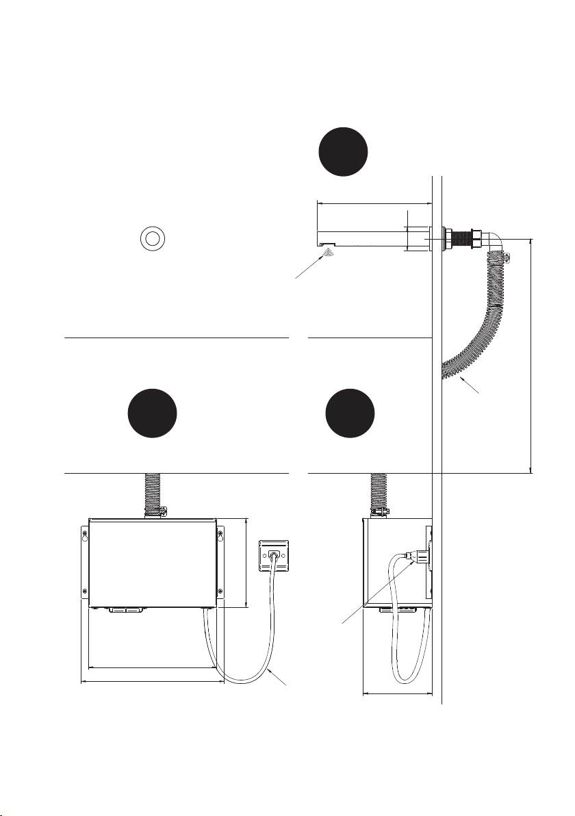
how to install
1 2
Fit dryer body into the 1 3 16" hole in wall.- /
Ø -/"1 3 16
8 + TSL.C.060 CHANNEL HAND DRYER MANUAL
Drill hole 1 3 16" diameter in wall 8-10" - /
above the bottom of the basin.

When step 3 is finished, run the sensor wire
and ground wire through angled pipe and fix
it to the fixing nut.
43
Thread the sensor and cables ground
through the gasket, washer and
fixing nut, and tighten the nut
against the installation wall.
TSL.C.060 CHANNEL HAND DRYER MANUAL + 9
how to install
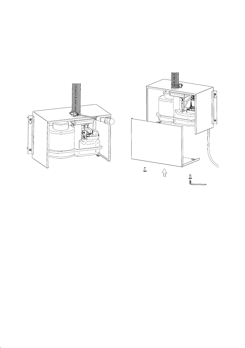
Fit the dryer motor unit to wall or cabinet,
within 48" of the dryer nozzle already
installed in the wall.
6
10 + TSL.C.060 CHANNEL HAND DRYER MANUAL
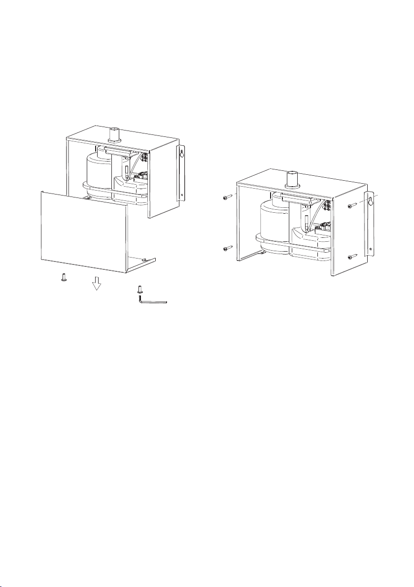
Remove cover-fixing screws from
underside of dryer motor using the
security hex key provided, and then
remove the cover.
5
TSL.C.060 CHANNEL HAND DRYER MANUAL + 11
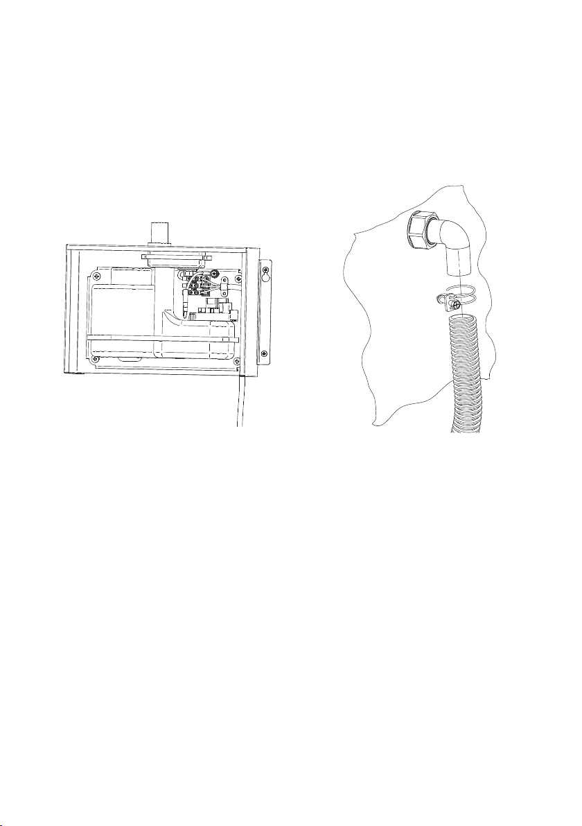
Feed sensor cable through angled pipe
connector and fit flexible hose.
8
Thread the power cable through the
knockout in the back or base of the dryer
and feed to connector block. Connect
the cables as marked on the dryer unit.
(Cable supplied pre-fitted)
7
how to install
Fasten pipe clip and tighten with
screwdriver.
10
12 + TSL.C.060 CHANNEL HAND DRYER MANUAL
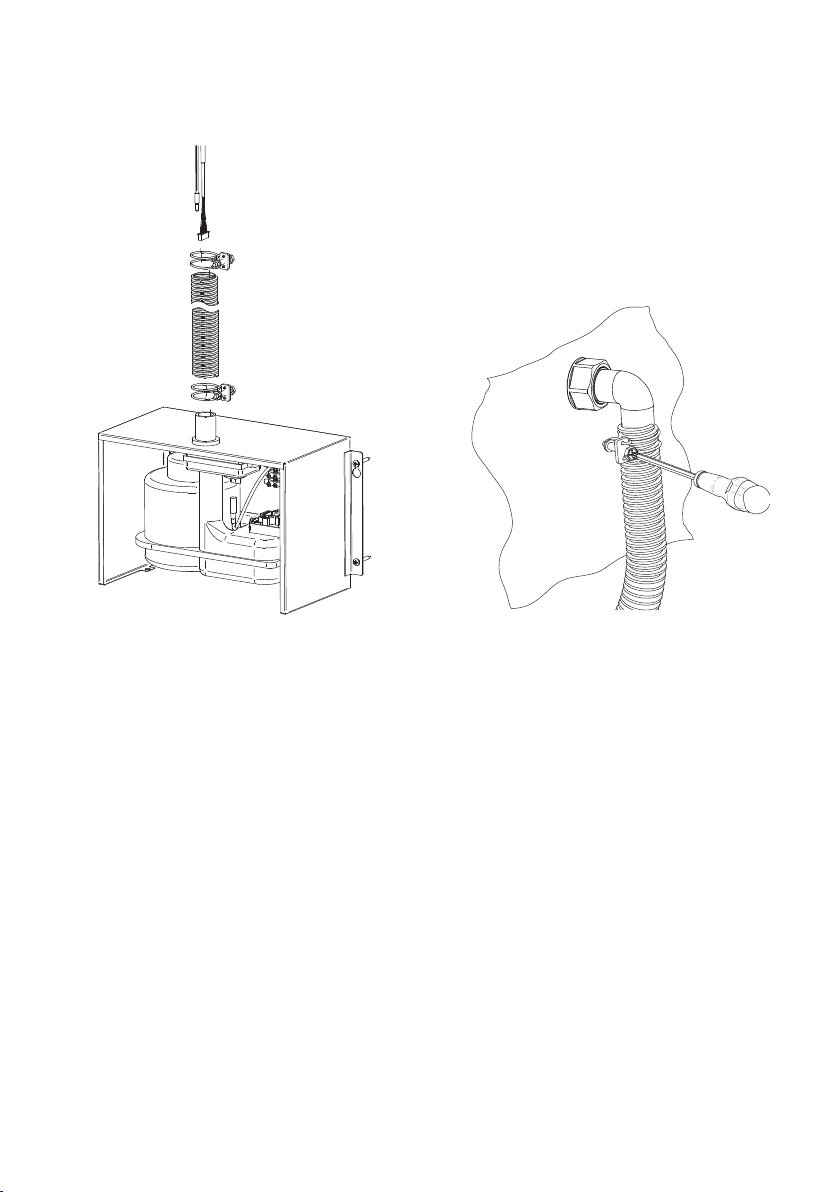
9
Thread the sensor and ground cables
through the air-hose.

12
Connect the sensor cable to the 6-pin
fitting on the PCB control, and the
ground cable to the corresponding earth
connector in the dryer motor unit.
TSL.C.060 CHANNEL HAND DRYER MANUAL + 13
11
Feed cables into air outlet nozzle and
then through cable exit grommet.
Note: grommet is split to allow cable
installation.
14
Re-fit the dryer cover and tighten the
fixing screws.
how to install
14 + TSL.C.060 CHANNEL HAND DRYER MANUAL
13
Connect air hose onto outlet nozzle on
dryer motor and tighten hose clamp.
Turn on the power supply to the dryer, and then test that the dryer will operate when
the user’s hands are placed within the detection range.
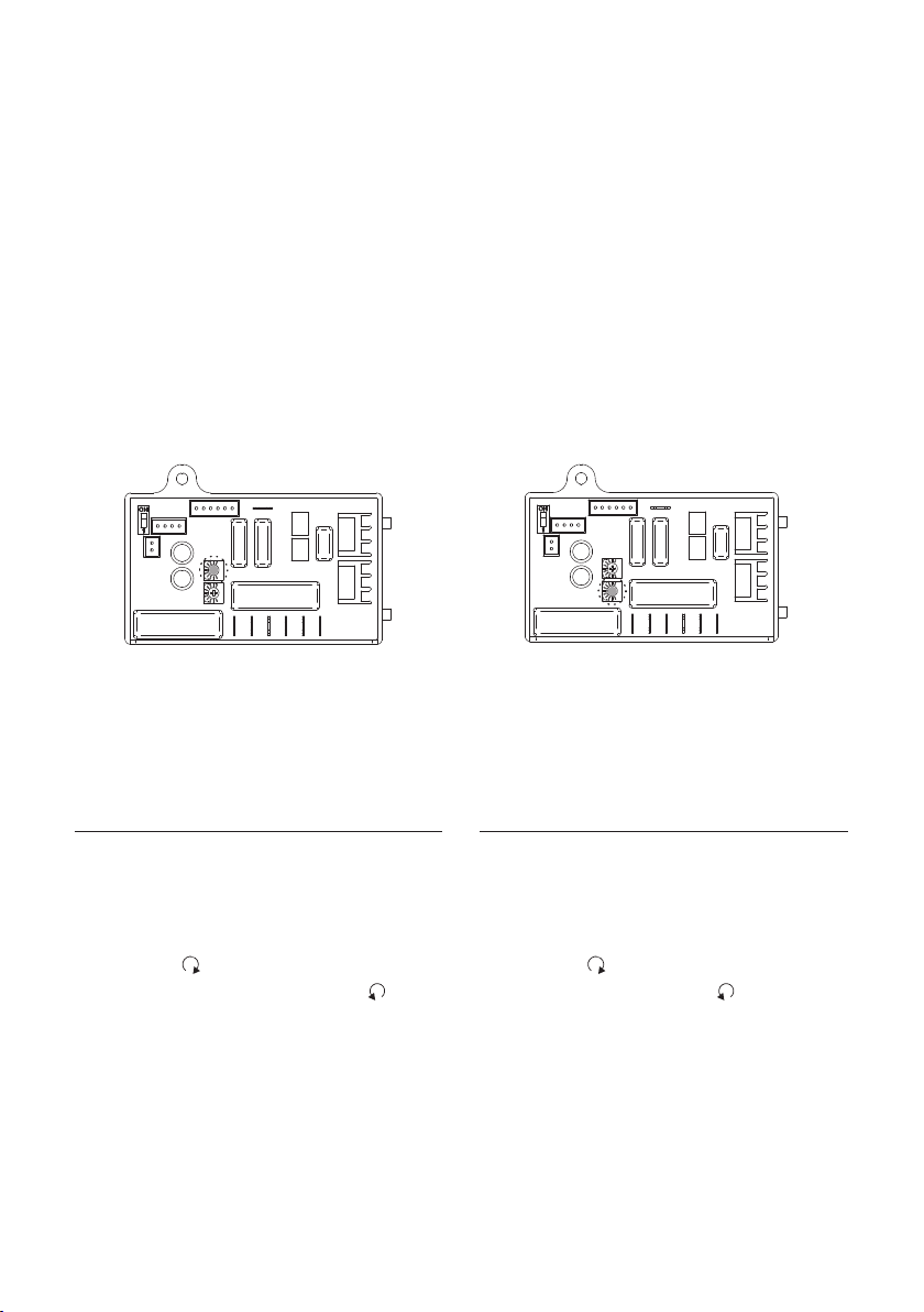
The motor speed and sensor range can be adjusted to suit user preference and the
environment, if required. The heater element can also be switched of f if desired.
Warm air speed adjustment
1.Switch of f the power, loosen the cover
screws and remove the cover.
2.Use small Phillips head screwdriver
to turn variable resistor shaft. Turn
clockwise to increase the motor
speed; turn counter-clockwise
to reduce the motor speed.
Sensor range adjustment
1.Switch of f the power, loosen the cover
screws and remove the cover.
2.Use small Phillips head screwdriver
to adjust the variable resistor. Turn
clockwise to increase the sensitivity;
turn counter--clockwise to reduce
the range.
commissioning
TSL.C.060 CHANNEL HAND DRYER MANUAL + 15
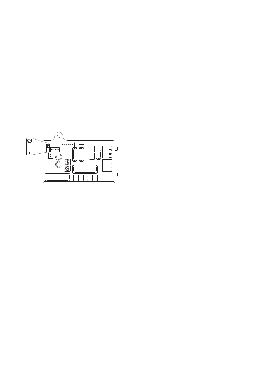
1. Switch of f the power, loosen the
cover screws and remove the cover.
2. Adjust the heater switch on the
PCB with a small plastic or wood
flat blade probe.
2-1 Slide the switch to ‘ON’:
Enables heater
2-2 Slide the switch to ‘1’:
Disables heater
Heater Element Switch ON/OFF
16 + TSL.C.060 CHANNEL HAND DRYER MANUAL
commissioning

+ The user is to shake excess water of f their hands.
+ The user then places their hands within the detection range of the sensor to
activatethehand dryer.
+ The motor will start and air is blown onto the user’s hands.
+ The motor will stop when the user’s hands are removed from the detection range.
maintenance
The hand dryer should be serviced on a regular basis to ensure long service life of
the unit.
+ Isolate the unit from the power supply before any servicing or maintenance work is
carried out.
+ Remove the cover by unscrewing the fixing screws on the underside of the cover.
+ Remove any dust or foreign body from the air intake and (both inside and outside
the dryer). Where necessary, use a brush or vacuum cleaner.
operation
+
TSL.C.060 CHANNEL HAND DRYER MANUAL + 17

All grades of stainless steel will stain or discolor if due care and attention is not
taken. The surface must be regularly cleaned to ensure a long service life of the
hand dryer.
Use a soft cloth or sponge with a mild solution of soapy water as part of the regular
washroom janitorial routine. Do not use abrasive or cream cleaners as these will
damage the surface finish.
If the hand dryer is subjected to a highly chlorinated environment e.g. swimming
pools or marine coastal locations, a further treatment, in addition to the regular
cleaning as described above, is recommended to use a household cleaning product
containing silicone.
If further information is required, contact The Splash Lab Team for more detailed
stainless steel care guidelines.
cleaning
+
+
+
+
18 + TSL.C.060 CHANNEL HAND DRYER MANUAL

If the dryer will not run:
+ First ensure that the breaker supplying the dryer is operational. If it is, disconnect
the power and remove the dryer cover. Taking suitable precautions to avoid shock
hazard, reconnect the power and check for voltage at the terminal block. Verify
that connections are made correctly.
The dryer cycles by itself or runs constantly:
+ Ensure that there is no obstruction on or in front of the IR sensor. Clean any dirt or
debris of f the sensor lens. If problem persists, replace sensor.
The dryer makes a loud noise and does not run for a complete cycle:
+ Ensure that the supply voltage is correct. Dryer will make a loud humming noise
if the input voltage is too high. Verify voltage requirement on unit rating label and
correct supply as required. (If circuit board module has been damaged, replace it
and the infra-red sensor module.)
The dryer runs but air stream is low pressure and/or low velocity:
+ Ensure that the supply voltage is correct. Dryer will run weakly if the input voltage
is too low. Verify voltage requirement on unit rating label and correct supply as
required.
initial installation
troubleshooting
We are always looking to improve. If these steps
did not solve your problem please contact us
and we will endeavor to help.
Tel: 310 410 5008
Email: info@thesplashlabusa.com
TSL.C.060 CHANNEL HAND DRYER MANUAL + 19

If the dryer will not run:
+ First ensure that the breaker supplying the dryer is operational. If it is, disconnect
the power and remove the dryer cover. Replace the CBM and IR sensor module.
Taking suitable precautions to avoid shock hazard, reconnect the power and
check for Voltage at the terminal block.
The IR sensor only sees close range objects:
+ Ensure that there is no obstruction on or in front of the IR sensor. Clean any dirt
or debris off the sensor lens. Check variable resistor for sensor range setting. If
problem persists, disconnect the power and remove the dryer cover and replace
CBM, IR sensor module.
The heater gets hot but no air stream is produced:
+ Disconnect the power. Remove the dryer cover. Check variable resistor for speed
setting. Disassemble the blower- motor/ fan housing. Replace the fan motor.
Reassemble.
in-service failure
troubleshooting
The dryer only blows cold air during a full cycle:
+ Disconnect the power. Remove the dryer cover and check/ ensure heater switch
is ON. Disassemble the blower- motor/ fan housing. Test the thermostat for open
circuit. Check the heater element for signs of burning or breakage. Damaged
element must be replaced.
The air stream is low pressure and velocity:
+ Check the output nozzle for obstructions, If none are present, disconnect the
power. Remove the dryer cover. Remove any dust/lint buildup from intake vent
slots. Check VR for speed setting. Disassemble the blower / motor / fan housing.
Check motor brushes for wear; if less than 1 1/4" is remaining. Replace brushes.
20 + TSL.C.060 CHANNEL HAND DRYER MANUAL
This manual suits for next models
5
Table of contents
Other Splash Lab Dryer manuals

Popular Dryer manuals by other brands

Maytag
Maytag MEDB700BW0 installation instructions

Bosch
Bosch WTG86400KE Installation and operating instructions

Frigidaire
Frigidaire FAQE7077KB - 7.0 CF Chrome TRIM Drum 7... Use and care guide

LG
LG RT8DIH1Q owner's manual

ATC
ATC Z-2000M manual

Tricity Bendix
Tricity Bendix TM 221 W Operating & installation instructions


