Splash StecaGrid 3600 User manual

info@splashmonitoring.com www.splashmonitoring.com
StecaGrid Inverter –Domestic Installation
Inverter summary
Inverter Manufacturer
Steca
Inverter Model
StecaGrid 3600
Inverter Size
3600W
Maximum number of inverters connected to a single
SPLASH Monitoring STREAMbox
99
List of parts required for connection of inverter to SPLASH Monitoring
To enable you to connect the above inverter to SPLASH Monitoring you will need a SPLASH Monitoring STREAMbox
and connection cables, these parts are listed below.
Part description
Part number
Inverter Make / Model
As above
SPLASH Monitoring STREAMbox
SMSB HW - Hardwired network and inverter connections
Connection cable STREAMbox to inverter
Part numbers Steca D9F-RJ45 3m
Steca D9F-RJ45 10m
Connection cable STREAMbox to clients router or LAN
Part numbers SM CAT5 1m –1m CAT5 cable
SM CAT5 2m –2m CAT5 cable
SM CAT5 5m –5m CAT5 cable
SM CAT5 10m –10m CAT5 cable
Optional
USB to RS485 D9F Adapter

info@splashmonitoring.com www.splashmonitoring.com
Installation Guidelines
We have found that the most reliable long-term results are achieved when the Streambox, DL2 and their respective
power supplies are installed well away from daily operational areas. The problem is that the loss of the Splash
Monitoring service is not immediately obvious, so it can be many days or weeks before someone realises that their
system is not being updated. We are in the process of developing a mechanism to detect the loss of communication
which optionally sends an email alert to one or more nominated recipients, but it is always prudent to minimise the risk
of disruption byfollowing these guidelines:
If possible install the equipment and power supplies well away from daily operational areas such as someone’s desk or
work bench.
Try and secure the equipment by attaching it to a wall or shelf with screws, Velcro or double sided tape. This should
prevent it from slipping and becoming disconnected.
Always secure the STREAMbox power cord to the STREAMbox using the P clip supplied. The P clip should be
located on the back of the STREAMbox using one of the existing jack posts, as illustrated:
Always ensure the LAN cables you use are in sound condition with their retaining clips intact, and make sure they are
securelyfitted to the equipment bygiving them a gentle tug.
Always ensure that all cables are secured using cable ties to protect them from accidental snagging.
Never stretch cables to the point where any movement could cause them to become dislodged.
Always install the STREAMbox with the ridged heat sink outwards and the side vents unobstructed. It doesn’t matter
what orientation is used; horizontallyon its bottom (the flat black surface); or vertically on its side.
The equipment and power supplies will be labelled ‘DO NOT SWITCH OFF’, but you should inform people with access
to the installation area that this equipment should not be turned off;for example cleaning and maintenance personnel.
info@splashmonitoring.com www.splashmonitoring.com
Basic Connectivity
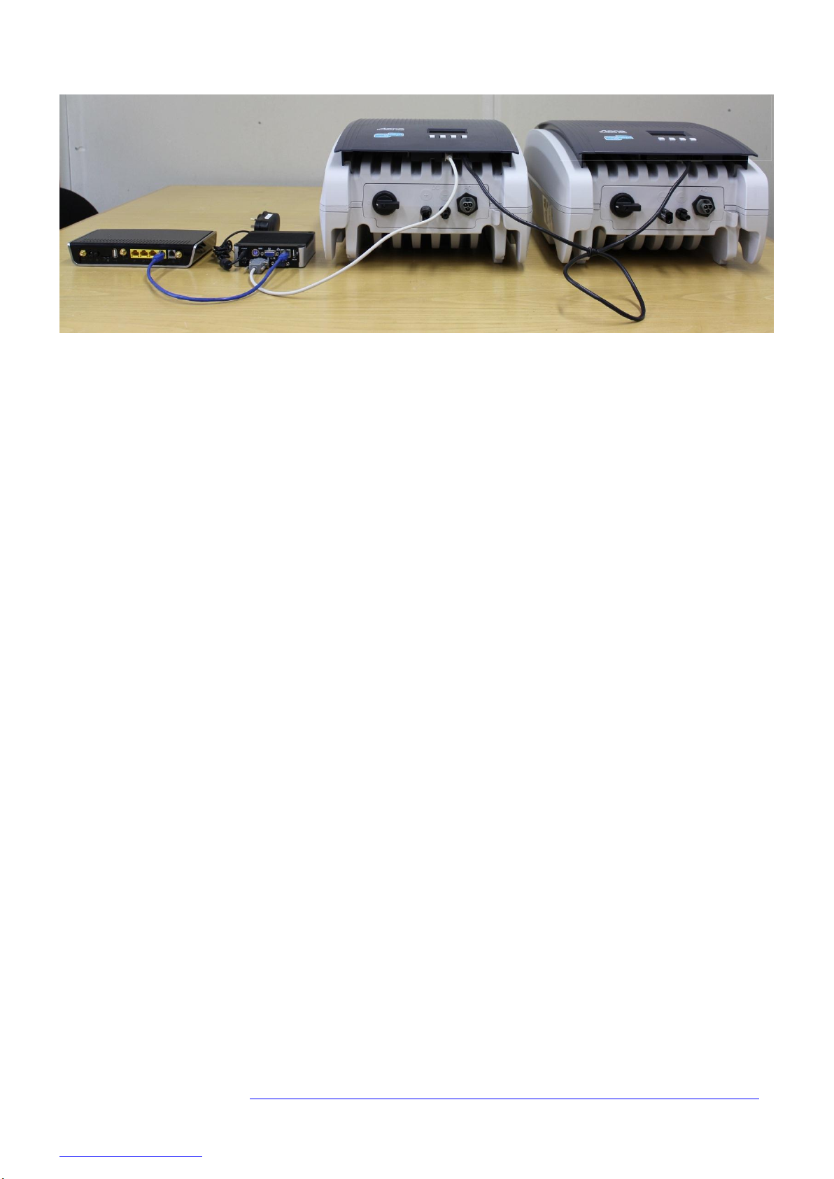
The photo above shows the connectivity between the various devices. The connections from left to right are:
1 –CAT5 or CAT6 LAN cable between the STREAMbox and your LAN, router or Network Access Device (blue cable).
2 –D9 to RJ45 cable between COM1 on the STREAMbox and the first inverter (beige cable).
3 –CAT5 or CAT6 extension cable between inverters (black cable).
The terminator switch to the left of the RJ45 sockets on the first inverter should be in the left hand position (unterminated),
as should all subsequent inverters except the last one where the terminator switch should be in the right hand position
(terminated).
Network Access Device: This maybe a Router, ADSL Modem, Switch or other network device connected to the Internet.
Please take care when connecting the inverter(s) to the STREAMbox, if the distances are long then SPLASH Monitoring
approved twisted pair cable is crucial.
Setting Up Your STREAMbox
Unless the STREAMbox has already been configured according to your specifications, it will be configured to acquire a
DHCP IP address from your router or DHCP server. For most domestic applications this will work without any
modification. However, if you do need to change its settings see below for guidance.
Trouble Shooting:
“No Stream Found” on the SM Web site:
This is because the web site hasn’t received any data from the STREAMbox.
Steca inverters can be interrogated for data if the AC power is connected, so make sure the inverter is powered
up.
Allow at least 10 minutes after powering up the STREAMbox before starting your diagnostic checks.
Check the connections between the STREAMbox and your router and ensure you have a solid green light at the
top left of the RJ45 socket and a flashing green light at the top right of the socket.
No solid green light could indicate: the STREAMbox is switched off (check the power light on the front of the
STREAMbox); or the router isn’t powered up, or the LAN cable isn’t connected to the router; or the LAN cable is
faulty. To eliminate the LAN cable and router, connect the LAN cable to a known working device like your laptop
or PC and if you can get a web session, then the LAN connectivity is OK.
Check the connection between the STREAMbox and the inverter. There’s not much you can do other than check
the physical connections at the STREAMbox, USBconverter and the inverter.
Try power cycling the STREAMbox –switch it off, wait 5 sec, switch it back on.
Try logging on to the STREAMbox: enter “splash” in your web browser’s address line, or if your STREAMbox has
a fixed IP address, enter that into your web browser. For instructions on how to use the STREAMbox’s ‘Web
Information Page’ go to http://www.splashmonitoring.com/assets/SM-STREAMbox-Web-Information-Page.html

info@splashmonitoring.com www.splashmonitoring.com
The most common issue we encounter is the site’s network firewall not allowing outbound traffic. This is rarely an
issue with domestic routers, but very common in managed commercial networks. Unless you have someone you
can ask (like a network administrator) a good way to detect this issue is to log onto the STREAMbox and run a
‘Healthcheck’ report. This will give you lots of information including whether the STREAMbox can ‘see’ the
internet.
The STREAMbox is notable to work with a proxyserver. If you have a proxyserver you will need tomake special
arrangements with your network administrator to have the STREAMbox circumnavigate it by issuing a fixed IP
address with appropriate privileges.
Generally there must only be on ‘master’ device on an RS422/RS485 bus. The STREAMbox is a master device
and as such can be the only one attached to your inverters, so make sure you don’t have another data logging
device attached to the RS422/RS485 bus. It will very likely work intermittently, but the data flow will be unreliable
and possibly corrupt if there are multiple master devices attached.
If you have multiple inverters attached to the STREAMbox, make sure each one has a unique address. You can
see the inverter’s address in the front panel display (on the StecaGrid: press ‘set’; down-arrow to ‘settings’; press
‘set’; down-arrow to ‘address’; press ‘set’.

info@splashmonitoring.com www.splashmonitoring.com
Inverter Status Codes:
On the Splash Monitoring web site we present four Labels for each inverter: “Full Status Code”; “Error Code”; “Warning
Code”; and “Information Code”. At any one time the inverter could be in a number of different states. For example it could
have a “Mains Voltage too high” error (Code Number 1) and at the same time have an “Isolation Error” (Code Number 11).
In these circumstances the STREAMbox will send each error alternately on subsequent scans. On the web site you will
see the “Error Code” flip-flop between these two values on each scan.
In this example the “Full Status Code” will be “401” which is the sum of the “Mains Voltage too high” flag “00000001” and
the “Isolation Error” flag “00000400” from the table below.
Separating the Errors, Warnings and Information codes means you can set different levels of alert on the web site. For
example: if the “Error Code” is greater than 0, send an SMS to a maintenance engineer; whereas if the “Warning Code” is
greater than 0, send an email to yourself. For information on how to set up alerts see the “Alerts” button on your SPLASH
Monitoring Dashboard.
Code
Number
Flag
Error description
Error(F)
Warning(W)
Information(I)
Permanent *
0
00000000
NoErrors or Warnings or Information
1
00000001
Mains voltage too high
E
2
00000002
Locked (used in older application)
I
3
00000004
Locked (used in older application)
I
4
00000008
Mains voltage too low
E
5
00000010
Locked (used in older application)
I
6
00000020
Locked (used in older application)
I
7
00000040
Mains frequencytoo high
E
8
00000080
Mains frequencytoo low
E
9
00000100
Residual current too high
E
10
00000200
Mains DC current too high
E
11
00000400
Isolation error
E
*
12
00000800
Invalid countrycode or no countrycode selected
E
*
13
00001000
DC-Input voltage too high
E
*
14
00002000
DC-Input voltage too low
W
15
00004000
Internal error: Error
E
*
16
00008000
Internal error:Warning
W
*
17
00010000
Internal error: Information
I
*
18
00020000
Derating temperature
W
19
00040000
Derating 10 minutes average value
W
20
00080000
Derating external (p.E. EVU)
W
21
00100000
Derating temperature > 30Min
W
22
00200000
Derating 10 minutes average value > 30Min
W
23
00400000
Derating external (p.E. EVU) > 30Min
W
24
00800000
Date/time not set
I
25
01000000
Option card error
I
*
26
02000000
24h no energy injection
E
*
27
04000000
PE connection lost (just not implemented)
E
*
28
08000000
L and N changed (just not implemented)
E
*
29
10000000
Second line connected to N (just not implemented)
E
*
30
20000000
Grid error (Disconnection by ENS or grid islanding
detected)
E
*
31
40000000
ENS Self Test failed
E
32
80000000
Fan error detected
W

info@splashmonitoring.com www.splashmonitoring.com
Trouble Shooting:
“No Stream Found” on the SM Web site:
This is because the web site hasn’t received any data from the STREAMbox.
Allow at least 10 minutes after powering up the STREAMbox before starting your diagnostic checks.
Check the connections between the STREAMbox and your router and ensure you have a solid green light at the
top left of the RJ45 socket and a flashing green light at the top right of the socket.
No solid green light could indicate: the STREAMbox is switched off (check the power light on the front of the
STREAMbox); or the router isn’t powered up, or the LAN cable isn’t connected to the router; or the LAN cable is
faulty. To eliminate the LAN cable and router, connect the LAN cable to a known working device like your laptop
or PC and if you can get a web session, then the LAN connectivity is OK.
Check the connection between the STREAMbox and the inverter. There’s not much you can do other than check
the physical connections at the STREAMbox, USBconverter and the inverter.
Try power cycling the STREAMbox –switch it off, wait 5 sec, switch it back on.
Try logging on to the STREAMbox: enter “splash” in your web browser’s address line, or if your STREAMbox has
a fixed IP address, enter that into your web browser. For instructions on how to use the STREAMbox’s ‘Web
Information Page’ go to http://www.splashmonitoring.com/assets/SM-STREAMbox-Web-Information-Page.html
The most common issue we encounter is the site’s network firewall not allowing outbound traffic. This is rarely an
issue with domestic routers, but very common in managed commercial networks. Unless you have someone you
can ask (like a network administrator) a good way to detect this issue is to log onto the STREAMbox and run a
‘Healthcheck’ report. This will give you lots of information including whether the STREAMbox can ‘see’ the
internet.
The STREAMbox is notable to work with a proxyserver. If you have a proxyserver you will need tomake special
arrangements with your network administrator to have the STREAMbox circumnavigate it by issuing a fixed IP
address with appropriate privileges.
Generally there must only be on ‘master’ device on an RS422/RS485 bus. The STREAMbox is a master device
and as such can be the only one attached to your inverters, so make sure you don’t have another data logging
device attached to the RS422/RS485 bus. It will very likely work intermittently, but the data flow will be unreliable
and possibly corrupt if there are multiple master devices attached.
Other Splash Inverter manuals

Popular Inverter manuals by other brands

MSW Motor Technics
MSW Motor Technics S-POWER UPS 800 PSW user manual

Outline
Outline NG01 user manual

blubase
blubase roboost Roof Tiles Portrait manual

Mitsubishi Electric
Mitsubishi Electric FR-D720-070 instruction manual

Samlexpower
Samlexpower PSE-12125A owner's manual

CARLO GAVAZZI
CARLO GAVAZZI G38900014 user manual


Mastervolt
Mastervolt Whisper 6 user manual

Parkside
Parkside PSE 2800 A1 Operation and safety notes

Champion Global Power Equipment
Champion Global Power Equipment 201110 quick start guide

Kostal
Kostal PLENTICORE plus Short manual

Sealey
Sealey PSI300.V2 instructions

UnitedPower
UnitedPower IG3600S instruction manual