CARLO GAVAZZI G38900014 User manual

G38xx14 Configuration Software
2001 Carlo Gavazzi Industri A/S. All rights reserved.
1
INTRODUCTION
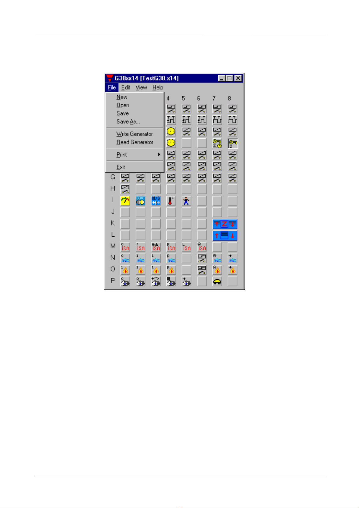
The G38xx14 program has been designed for configuration of the G38900014 master generator.
All functions in the generator are represented by graphic symbols. To each channel function are
related parameters and comments, which can be edited locally in the PC and transferred to the
master generator through RS232. Likewise, data from the master generator can be uploaded and
edited.
Hardware Requirements
The program operates under Windows 95/98 and NT and requires at least:
• 486 processor with 8 Mbytes RAM or higher.
• A free serial port (Com1 or Com2).
• 5 Mbytes hard disk for installation.
• Screen resolution of 640 x 480 pixels, 256 colours or higher.
• Mouse or other pointing tool desirable, but not necessary.
Installation
Insert disk 1 in the A-drive and run the program “Setup.exe”. This will guide you through the
installation process. After installation, the program can be started by clicking G38xx14.
Start up of program
When G38xx14 is started, two windows will open:
To the left, the main window showing the 128 channels available in Dupline and menus. To the
right, the properties window, which for each function shows the parameters related to this
particular function.

G38xx14 Configuration Software
FUNCTIONS IN THE MAIN WINDOW
File menu
The file menu contains the usual functions:
New: Start from the beginning with default data
Open: Open existing file
Save: Save file
Save As: Save file under new name
Write Generator: Write data to the Generator
Read Generator: Read data from the Generator
Print: The following options are available:
Print-out of:
Address Listing
Master Channels
Real time Channels or
Logic Settings
SMS Setup
2001 Carlo Gavazzi Industri A/S. All rights reserved.
2

G38xx14 Configuration Software
Exit: Exit program
Edit menu
Basic Set-up: General information and major part of set-up of the G38900014 generator
Logic Set-up: Configuration of logic functions
Holiday Set-up: Set-up of holiday period. The holiday set-up is active when the current
date falls within any of the set time intervals
Two Dupline
networks: Two channel generators G38900014 can be connected via the
communication cable. Thereby addresses, ie master commands, can be
transferred from one network to the other
SMS Set-up: For sending status and receiving commands to/from a GSM-phone via the
Dupline GSM8 modem. Access to the Master Generator is Password and
“dial up number” protected.
View menu
Language: You can select 3 preferred languages or select other languages to be
immediately available in your View-Language menu
Serial port: Selection of Com 1 or Com 2 port, for connection of the G38900014
generator
Help menu
General information: You can call the Help menu at any time by pressing F1
About program: Shows the opening screen
2001 Carlo Gavazzi Industri A/S. All rights reserved.
3

G38xx14 Configuration Software
Selection of channel functions
When the basic settings have been made under “Basic Set-up”, the functions of the remaining
channels to be used are defined as follows:
Activate one of the channels, then click on right mouse button for pop-up menu. Click on the
desired channel type with left mouse button. The channel is thereby assigned a symbol indicating
the selected channel type. Click on the symbol with left mouse button, and the parameters which
can be set for that particular channel function can be viewed in the properties window.
The arrow keys can also be used to select channel function in the pop-up menu.
Furthermore, channel function can be selected by clicking on different letters. To be able to select
functions by clicking on letters, click on the Title bar. The letters and the related channel functions
can be seen by clicking F1 for help:
2001 Carlo Gavazzi Industri A/S. All rights reserved.
4

G38xx14 Configuration Software
Tool tip
When the curser is positioned on a channel button, a bar appears indicating channel number,
describing channel type and showing the user-defined channel description.
2001 Carlo Gavazzi Industri A/S. All rights reserved.
5

G38xx14 Configuration Software
FUNCTIONS IN THE PROPERTIES WINDOW
Basic Set-up
ID can be set up for the Master Generator.
When using “Two Dupline Networks”, the ID
must be set to “00”
Events can be sent to printer or
sent/received from SMS
Counter can be set up to
2, 4, 6 or 8 digits
The text window is for entering general information, eg name of user, date of configuration, etc.
By clicking in the first checkbox, time and date is transferred from the PC to the G38900014. The
program shows the updated time and date from the Windows System for checking. If the PC does
not show the correct time, the clock can be adjusted in the usual way, ref. Windows Handbook.
By clicking in the second checkbox, the G38900014 automatically switches between summer and
winter time.
Under Basic Set-up the user selects the amount of channels he wants to use. Also multiplexing
can be selected here as well as the channels on which the time shall be output on Dupline.
2001 Carlo Gavazzi Industri A/S. All rights reserved.
6

G38xx14 Configuration Software
2001 Carlo Gavazzi Industri A/S. All rights reserved.
7
Logic Set-up
Selection of logic
block
Channel used as
output for logic
function
Channel used as
input for logic
function
Triggering on
leading or trailing
edge
Text field for
comments. A text
field for each logic
block
Selection of type
of function: AND,
OR or XOR
Logic functions are divided into 8 blocks. Each block consists of 8 gate definitions and a text
window for description. For all gate fields there are Tool-Tips showing valid entries. Click on F1 for
help. All inputs are (+) as standard. If an input should be (-), the (-) is put in front of the address, eg
-D4.
Use the Up- and Down-keys to move between the lines and the Left- and Right-keys to move the
cursor within the same line. Write A, O or X when the cursor is in the function field. The logic line is
deleted by placing the cursor in the function field and pressing the space key.
Edge triggering is possible. < / > means triggering on the leading edge, while < \ > means
triggering on the trailing edge of a given address. The edge sign toggles on pressing < / >.

G38xx14 Configuration Software
Monostable (Pushbutton), Blank and Bistabile (Toggle switch) channels
The channel is to
be used in the
intruder alarm.
When the intruder
alarm is activated,
this channel too
may give a signal
to start the
Intruder alarm.
When “Print when On” is selected, this
indicates that whenever the channel goes
from off-condition to on-condition, the
channel and its description is sent out on a
printer on the parallel port.
If the “Channel Events output to” in the
Basic Setup is set to “SMS Message”, the
change will be sent as an SMS message.
User description of the
channel. The text is
shown in Tool Tip on
the channel buttons in
the main window.
For every channel type there is a field for user description. Blank channels do not require any
parameters. For a monostable channel, the function can be inverted, and for a bistable channel, it
is selected whether the channel is to be used in the Intruder alarm.
2001 Carlo Gavazzi Industri A/S. All rights reserved.
8

G38xx14 Configuration Software
Timer channels
Selection of
function of timer
channel
The On-delay
is started by a
short pulse
Entering of
On-delay
Additional channel
with which the
function is enabled
Entering of
Off-delay
When the timer function is changed, the icon of the channel button is also changed.
2001 Carlo Gavazzi Industri A/S. All rights reserved.
9

G38xx14 Configuration Software
Real-time channels
Time entries for
channel ON and
channel OFF
Selection of days
of the week for
automatic switch-
ing on and off.
Days are selected
with left mouse
button
You need only enter a
time indication for
switching ON or switching
OFF
In this case the
channel will switch
off on weekdays at
23:00, but not on
Saturdays and
Sundays
Note: By entering a minus
in the time field, the ON-
time/OFF-time is deleted
Disabled since no
time has been
defined for neither
switching on nor
switching off
Editing of real-time channels. Use the Right- and Left-keys to move the cursor within the lines.
2001 Carlo Gavazzi Industri A/S. All rights reserved.
10

G38xx14 Configuration Software
2001 Carlo Gavazzi Industri A/S. All rights reserved.
11
Master Function
Cursor position
indicates selected
channel
Channel not
controllable by
master function, ie
either another
master function or
an alarm channel
Pop-Up menu
appears by clicking
right mouse button
The master function
is to include a real
time function
When a real time
function is included,
a matrix can be
opened in which to
enter switch times
When the properties window is active, the master function can also be edited by means of the
arrow keys and the keys 0, 1 and X.
Activate F1 for additional help on this function.

G38xx14 Configuration Software
Roller Blind Functions
Roll time defines for
how long the Roller
blind must be in
operation before it
stops
Master function
operates on these
channels
Selection of how
the Master function
operates on the
selected Up/Down
channels
This function is
to include the
adjustment of
tiltin
g
blinds
A channel or flag can be
entered by which the up-
direction or the down-
direction of the roller blinds
is given priority
Delay before the
roller blind
changes direction
The reverse Up
time defines for how
long the roller blinds
must run in the
opposite direction
after expiry of the
roll time. Applies
only to Tilting Blinds
Roll time defines for
how long the Roller
blind must be in
operation before it
sto
p
s
Master function channels consist of both an Up-channel and a Down-channel. Operating the
master up will cause all roller blinds comprised by this master to start moving up. Either
simultaneously or one by one with 2 secs intervals (sequentially).
2001 Carlo Gavazzi Industri A/S. All rights reserved.
12

G38xx14 Configuration Software
AnaLink Sensors
Motion Detector
Input range
defined for
Analink sensor
G8911 1010
-30°C to +60°C
Entry of the channel
with which to
disable the channel
With this control
output, the channel
can be used to
switch on a relay for
instance
Select this option to
invert the switching
function in relation
to the limit values
Entry of upper and
lower limit values
Select this option to
open a second
entry form into
which a second pair
of limit values can
be entered
Entry of the address
which is to enable
the second pair of
limit values
When selecting this
option, the Analink
signal is provided
by another Analink
channel.
Entry of the channel
from which the
alternative analog
value is to be read.
The motion
detector activates
the siren/alarm
signal in the
Intruder alarm.
When the Intruder
alarm is
activated, this
channel too may
give a signal to
start the Intruder
alarm
Number of allowed pulses within a 10
secs time frame before the motion
detector gives out its alarm signal
Entry of off delay
2001 Carlo Gavazzi Industri A/S. All rights reserved.
13

G38xx14 Configuration Software
ISA alarm
Only one
Acknowledge,
Reset, Lamp test
and Siren channel
can be assigned
ISA Operation mode
either Standard or
Auto-reset.
In Auto-reset mode
the Reset channel
cannot be selected
By activating the
Disable channel,
the detector is
removed from the
alarm surveillance
Entry of On-
delay after
which the alarm
is activated
2001 Carlo Gavazzi Industri A/S. All rights reserved.
14

G38xx14 Configuration Software
Water and Smoke alarm
By activating the set
Disable channel, the
detector is removed
from the alarm
surveillance
The water and
smoke alarm
are designed
identically
Only one Alarm
siren and one
Alarm signal
channel can be
selected for the
water alarm
2001 Carlo Gavazzi Industri A/S. All rights reserved.
15

G38xx14 Configuration Software
Intruder alarm
The armouring and
desarmouring delays
apply to manual -,
door lock- and code lock
armouring
The detector channels
can be disabled by
another channel, as is
the case with water-
and smoke detectors
Additional channels
can be selected to flash
together with the alarm
output channel
Click here to call a
matrix in which the
desired channels are
selected
Insert flash interval
Only one Alarm
siren and one Alarm
signal channel
can be selected
2001 Carlo Gavazzi Industri A/S. All rights reserved.
16

G38xx14 Configuration Software
2001 Carlo Gavazzi Industri A/S. All rights reserved.
17
Common siren
Selection of alarms
using common siren
The set siren time
applies to this
channel only.
The times are
identical with the
times specified
under the individual
alarms

G38xx14 Configuration Software
BASIC CHANNEL TYPES
A basic channel has its own specific function. The different functions have their associated
parameters which determine the operation of the channel. All basic channel types can be
controlled by a master channel and can be read and written via logic.
Monostable channel
Operation: A monostable channel (push button) transmits the function directly from transmitter to
receiver, ie normal Dupline point to point operation.
Parameters: Invert Function.
Flip-flop channel
Operation: A bistable channel (toggle switch) changes the status of the receiver for each new activation
of the transmitter. Used to turn on and off a function.
Parameters: A bistable channel can be used in the Intruder alarm. Example: When the light is switched
on, the Intruder alarm goes on.
Timer On-delay/Timer Off-delay
Operation: Timer On-delay:
Channel controlled by a timer. The receiver will turn on upon uninterrupted transmission for
the On-delay period. The timer restarts counting upon each start of transmission. Only upon
uninterrupted transmission for the On-delay period will the receiver turn on.
Channel Off-delay:
Channel controlled by a timer. The timer restarts counting upon start of transmission
whereby the receiver will turn on. When the transmission on the channel stops, the receiver
will remain active until the Off-delay has elapsed.
Parameters: Hours, minutes, seconds from 0,0,0 to 99,59,59.
The On-delay can be started by a short pulse (one shot on energization). If another short
pulse is given before elapse of the On-delay, the delay restarts. The On-delay will also run
when a continuous pulse is given. In that case, the Off-delay will only start when the
continuous pulse has stopped. Example: When the light in the bathroom has been on for 5
min (On-delay), the fan switches on for 10 min (Off-delay).
Timer Recycler
Operation: Channel controlled by a timer. When transmission takes place on this channel, the receiver
will turn on and off at the specified time intervals.
Parameters: Hours, minutes, seconds from 0,0,0 to 99,59,59.
2000 Carlo Gavazzi Industri A/S. All rights reserved.
18

G38xx14 Configuration Software
Blank channel
Operation: Channel not assigned for any operation. Since the transmitter signal and the receiver signal
are separated, transmission on this channel will not affect the output. Transmission can only
be used as input for Logic operations. The output may be controlled by either a master
function or by the logic functions.
Parameters: None.
Basic channel types with special functions
Real time
Operation: Turn-on/turn-off function is controlled by the built-in real time clock of the generator. Any
transmission pulse on this channel will toggle the output status regardless of whether it was
set manually or by a real-time switching event.
Parameters: 4 settings can be defined, each consisting of Switch-on time, Switch-off time, Operation days
of week and Holiday.
Master channel
Operation: A master channel can operate on all basic channel types. When transmission takes place on
this channel, the switch pattern is transferred to the selected basic channels to force these
into the predefined status.
Parameters: Definition of the switch pattern.
A real time function can be included and switch times entered.
The selected channels cannot change status as a result of transmission or Logic before the
master function is deactivated.
If more than one master channel have been defined, the one with the highest channel no.
will have the highest priority, eg master channel B1 will override A8, if both channels are
active at the same time. Each master channel can be freely assigned turn-on - turn-off -
ignore status for a random number of the basic channel types.
A master function cannot control another master function. Nor can a master function
influence channels with superior functions, eg water-, smoke-, intruder alarm.
The channels controlled by a master function will perform their individual functions as if
transmission had taken place on the channel.
2000 Carlo Gavazzi Industri A/S. All rights reserved.
19
Table of contents
Other CARLO GAVAZZI Inverter manuals
Popular Inverter manuals by other brands

Generac Power Systems
Generac Power Systems Guardian 005324-0 owner's manual

PAW
PAW SolexMega-Kaskade HZ Installation and commissioning instructions

SMA
SMA 10000TL user manual

Sportsman
Sportsman GEN4000DF-SS Step-By-Step Quick Start Guide

Honda
Honda E4500 owner's manual

Agilent Technologies
Agilent Technologies E4400B Configuration guide