Splash Bootloader User manual

E info@splashmonitoring.com Web. www.splashmonitoring.com
Technische Alternative Bootloader – Domestic Installation
Introduction
This document is intended to be a brief guide to the steps you need to take to set up your Bootloader. It assumes the
Controller (UVR1611 / UVR61) is already installed and connected to the solar sensors.
Installation Guidelines
We have found that the most reliable long-term results are achieved when the Streambox, Bootloader and their respective
power supplies are installed well away from daily operational areas. The problem is that the loss of the Splash Monitoring
service is not immediately obvious, so it can be many days or weeks before someone realises that their system is not
being updated. We are in the process of developing a mechanism to detect the loss of communication which optionally
sends an email alert to one or more nominated recipients, but it is always prudent to minimise the risk of disruption by
following these guidelines:
•If possible install the equipment and power supplies well away from daily operational areas such as someone’s
desk or work bench.
•Try and secure the equipment by attaching it to a wall or shelf with screws, Velcro or double sided tape. This
should prevent it from slipping and becoming disconnected.
•Always secure the STREAMbox power cord to the STREAMbox using the P clip supplied. The P clip should be
located on the back of the STREAMbox using one of the existing jack posts, as illustrated:
•Always ensure the LAN cables you use are in sound condition with their retaining clips intact, and make sure they
are securely fitted to the equipment by giving them a gentle tug.
•Always ensure that all cables are secured using cable ties to protect them from accidental snagging.
•Never stretch cables to the point where any movement could cause them to become dislodged.
•Always install the STREAMbox with the ridged heat sink outwards and the side vents unobstructed. It doesn’t
matter what orientation is used; horizontally on its bottom (the flat black surface); or vertically on its side.
•The equipment and power supplies will be labelled ‘DO NOT SWITCH OFF’, but you should inform people with
access to the installation area that this equipment should not be turned off; for example cleaning and
maintenance personnel.

Setting Up Your Bootloader
If the Bootloader has not already been configured by your supplier, then here are the steps you’ll need to take:
You will need:
•The Bootloader is powered directly from the UVR1611, or in the case of a UVR61 it needs a separate low voltage
power supply
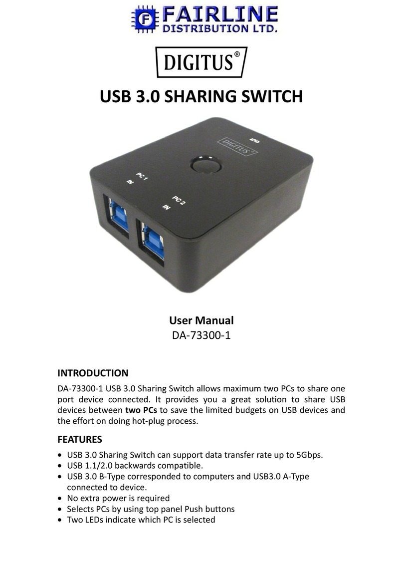
•A USB to small USB cable
•A Windows PC connected to the internet
•CAT5 or CAT6 cables to connect the Bootloader(s) and STREAMbox to the network
•Technische Alternative “Memory Manager” software on your PC
•Technische Alternative BL-NET Bootloader manual
•HTML and GIF files for the Bootloader
•An IP address for the Bootloader**
** Choosing an IP Address:
By default the STREAMbox will scan IP addresses aaa.bbb.ccc.210 through aaa.bbb.ccc.219, where aaa.bbb.ccc is the
network address provided by your router. You can find this address by going to the command prompt on your network
attached Windows PC and typing “ipconfig /all” at the command prompt. You should see something like:
Take the first three octets from the Default Gateway address (192.168.12) in the above example and add .210 to the end.
Therefore the IP address for the first Bootloader in this example will be 192.168.12.210. Subsequent Bootloaders attached
to the same network will be given IP addresses of 192.168.12.211, 192.168.12.212 and so on.
Configuration:
1. Plug the UVR1611 or separate power supply into the Bootloader.
2. Connect the USB cable from your PC to the Bootloader and start the Memory Manager software (see below for
instructions on how to get Memory Manager).
3. Reset the Bootloader IP address to your chosen address. See below for detailed instructions.
4. Connect the STREAMbox to the network and power it up.

5. After about 2 minutes check web access to the STREAMbox by entering http://splash/ into your web browser.
This requires a network name resolver (DNS) to be accessible on your network which isn’t always available, so it
may not work. The password is the first 5 characters of your fingerprint (see separate document for instructions
on the Streambox’s Web Information Page). The STREAMbox acquires an IP address from the DHCP server, so
if you’re able to determine this address you can use that instead of http://splash. **
6. After about 5 minutes log onto the Splash Monitoring web site and enter your fingerprint into the Dashboard and
click “Scan”. If the installation was successful you should see data from the Bootloader(s) appear.
7. If you have data on the Dashboard then you can go on to configure your site as described in the “Getting Started”
document.
** You can ascertain the IP address of the STREAMbox by plugging a monitor into the VGA socket on the back of the
STREAMbox, then switch off and back on to re-boot. At the end of the boot sequence the STREAMbox’s IP address will
be displayed on the monitor. Enter this IP address into your web browser to get the STREAMbox web information page.
Alternatively you could try entering ‘arp –a’ at the command prompt on your network attached Windows PC. This will
sometimes give the STREAMbox’s IP address as “splash.local (aaa.bbb.ccc.ddd) …..” where aaa.bbb.ccc.ddd is the
STREAMbox’s IP address.
Getting the Memory Manager Software
1. Remove any previous Memory Manager installs from your PC.
2. Download Memory Manager for the Bootloader from:
http://www.ta.co.at/en/downloads/software/memory-manager
Setting the IP address on the Bootloader.
1. Start Memory Manager.
2. Click Setup.
3. Run a COM test to see if it recognizes a T.A. Device
4. If you see T.A. as above example, click cancel and select the radio button that corresponds to the correct
COM port (in this case COM6). Click Save.

5. If you don't see a T.A. device in step 3, then you need to go to Control Panel-> Device Manager and find
the Serial USB Port. You may have to unplug/disable other USB devices until you can assign it to a Port
that the Memory Manager can communicate with (COM1-COM6) using the Properties -> Port Settings ->
Advanced -> COM Port Number.
6. Run Memory Manager -> Setup -> TEST COM, and you should get a T.A. status on the port you assigned in step
5.
7. Select the corresponding COM Port and click SAVE.
8. If you are processing several Bootloaders and are certain you are plugging the Bootloader into the same
USB port each time, leave the same COM port selected.
9. In Memory Manager -> Configure Bootloader, set the IP address of your Bootloader to the required IP address
10. Set the Subnet-Mask to 255.255.255.0 unless otherwise required.
11. Each Bootloader on the same network must have a unique BLD Number, so we suggest you set the BLD
Number to the same as the last octet of the IP address. Ie, for IP address 192.168.66.210 set the BLD Number to
210
12. The Gateway is not used so set it to 0.0.0.0, HTTP Port is always 80 and TA Port is not used so leave it at 40000.
13. Click OK, then Save.

14. The correct firmware, ‘on-line diagram html’ and ‘on-line diagram.gif’ should have already been installed on the
Bootloader by your supplier. However, if you need to reload them please obtain the appropriate versions of these
files from Splash Monitoring and consult your Bootloader manual for instructions on how to load them.
15. Plug the Bootloader into the LAN with an Ethernet cable.
16. In Memory Manager, enter the IP address and click Test IP, making certain that the IP matches what was set in
the Bootloader.
17. If this does not show a “success” result, it may be that your PC is not configured to communicate on the chosen
IP network. See separate Trouble-Shooting Guide.
18. Browse the IP address you set with "/GRAFIK.htm" added to the end (eg. 192.168.66.210/GRAFIK.htm), which
should show you the raw Bootloader values, or in the case of some Internet Explorer versions, you may need to
right click and "View Source" to see the result.
19. If after repeated attempts this process is unsuccessful, consult the separate Trouble-Shooting Guide available at
www.splashmonitoring.com/help .
Table of contents
