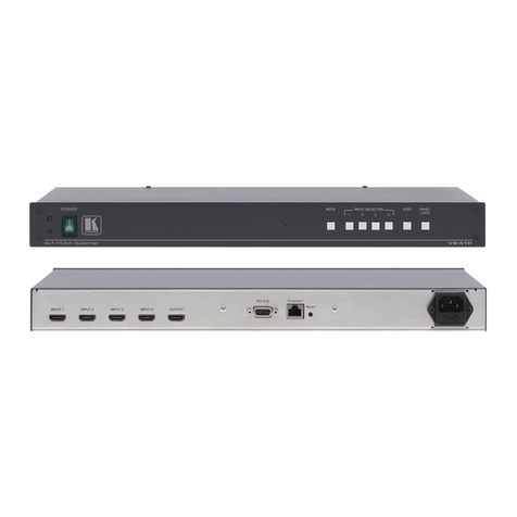
Kramer VS-41HDCP User manual

KRAMER ELECTRONICS LTD.
USER MANUAL
MODEL:
VS-41HDCP
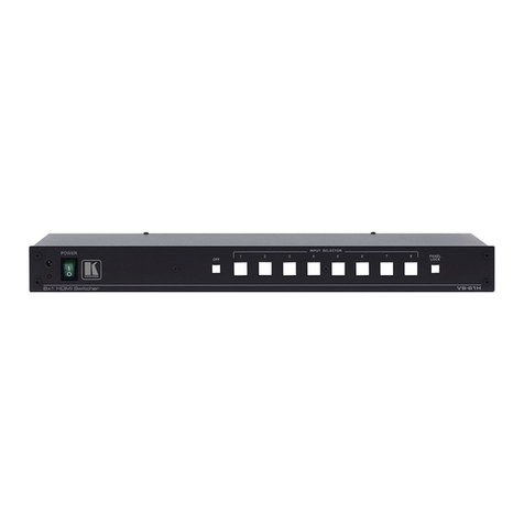
4x1DVI Switcher
P/N: 2900
-000522 Rev 1

Step 1: Check what’s in the box
VS-41HDCP Quick Start Guide
Step 2: Install the VS-41HDCP
Step 3: Connect the inputs and output
Mount the machine in a rack (using the RK-1 rack adapter) or place on a table.
This page guides you through a basic installation and first-time use of your .
For more detailed information, see VS-41HDCP
the user manual. You can download the latest
manual at .
VS-41HDCP
http://www.kramerelectronics.com
Save he original box and packaging materials in case your Kramer product needs to be returned to the
factory for service.
Always switch off the power on each device before connecting it to your .VS-41HDCP
For best results, we recommend that you always use Kramer high-performance cables to connect AV
equipment to the .VS-41HDCP
The 4x1 DVI Switcher
1 power adapter (5V DC)
VS-41HDCP
RC-IR3 IR remote control transmitter with batteries and user manual
4 rubber feet
1 Quick start sheet
1 User Manual
Step 4: Connect the power
Connect the 5V DC power adapter to the and plug the adapter into the mains
electricity.
VS-41HDCP
Switch on the power to each device.
1. Connect the power supply.
2. Connect the new output display.
3. Press the EDID button.
4. Wait for the input buttons to stop blinking in sequence.
To acquire the default EDID, skip step 2 above.
Step 5: Operate the VS-41HDCP
Operate the also via the RS-232, remote control contact closure and IR remote
control. VS-41HDCP
Computer
Graphics
Source (PC)
Display PC Control
Device
Acquire the EDID:
Operate via the front panel buttons:


VS-41HDCP – Contents i
Contents
1Introduction 1
2Getting Started 2
2.1 Achieving the Best Performance 2
3Overview 3
3.1 Defining EDID 4
3.2 About HDCP 4
4Defining the VS-41HDCP 4x1 DVI Switcher 5
5Connecting a VS-41HDCP 4x1 DVI Switcher 6
5.1 Connecting to the VS-41HDCP via RS-232 7
6Operating the VS-41HDCP 8
6.1 Setting the EDID 8
6.2 Controlling via the REMOTE Terminal Block Connector 9
6.3 Controlling the VS-41HDCP via the ETHERNET Port 9
6.4 Operating the VS-41HDCP using a Web Browser 13
6.5 Log On to the VS-41HDCP Web Pages 14
7Firmware Upgrade 18
8Technical Specifications 19
8.1 Default Communication Parameters 19
9Default EDID 20
10 Kramer Protocol 21
10.1 Switching Protocols 21
10.2 Kramer Protocol 3000 22
10.3 Kramer Protocol 2000 24
Figures
UFigure 1: VS-41HDCP 4x1 DVI Switcher Front PanelU5
UFigure 2: VS-41HDCP 4x1 DVI Switcher Rear PanelU5
UFigure 3: Connecting a VS-41HDCP 4x1 DVI SwitcherU7
UFigure 4: Connecting the Contact Closure Remote Control PINsU9
UFigure 5: Local Area Connection Properties WindowU10
UFigure 6: Internet Protocol (TCP/IP) Properties WindowU11
UFigure 7: Connect ScreenU12
UFigure 8: Device Properties ScreenU13
UFigure 9: Java Test Page Success MessageU14
UFigure 10: The Loading PageU14
UFigure 11: First Time Security WarningU15
UFigure 12: VS-41HDCP Switching Matrix PageU16
UFigure 13: Configurations PageU17

VS-41HDCP - Introduction 1
1 Introduction
Welcome to Kramer Electronics! Since 1981, Kramer Electronics has been
providing a world of unique, creative, and affordable solutions to the vast range of
problems that confront the video, audio, presentation, and broadcasting
professional on a daily basis. In recent years, we have redesigned and upgraded
most of our line, making the best even better! Our 1,000-plus different models now
appear in 11 groups that are clearly defined by function.
Our 1,000-plus different models now appear in 11 groups that are clearly defined by
function: GROUP 1: Distribution Amplifiers; GROUP 2: Switchers and Matrix
Switchers; GROUP 3: Control Systems; GROUP 4: Format/Standards Converters;
GROUP 5: Range Extenders and Repeaters; GROUP 6: Specialty AV Products;
GROUP 7: Scan Converters and Scalers; GROUP 8: Cables and Connectors;
GROUP 9: Room Connectivity; GROUP 10: Accessories and Rack Adapters;
GROUP 11: Sierra Products.
Congratulations on purchasing your Kramer VS-41HDCP 4x1 DVI Switcher. The
VS-41HDCP is ideal for conference room presentations and advertising
applications, as well as for rental and staging.

2 VS-41HDCP - Getting Started
2 Getting Started
We recommend that you:
•Unpack the equipment carefully and save the original box and packaging
materials for possible future shipment
•Review the contents of this user manual
•Use Kramer high-performance high-resolution cables
•Use only the power cord that is supplied with this machine
i
Go to http://www.kramerelectronics.com to check for up-to-date user
manuals, application programs (where appropriate), and to check if
firmware upgrades are available.
2.1 Achieving the Best Performance
To achieve the best performance:
•Use only good quality connection cables to avoid interference, deterioration in
signal quality due to poor matching, and elevated noise levels (often
associated with low quality cables)
•Avoid interference from neighboring electrical appliances that may adversely
influence signal quality
•Position your Kramer VS-41HDCP away from moisture, excessive sunlight
and dust
!
Caution: No operator serviceable parts inside the unit
Warning: Use only the Kramer Electronics input power wall
adapter that is provided with the unit
Warning: Disconnect the power and unplug the unit from the wall
before installing

VS-41HDCP - Overview 3
3 Overview
The VS-41HDCP is a high quality 4x1 switcher for DVI signals that supports up to
2.25Gbps bandwidth per graphic channel (suitable for resolutions up to UXGA at
60Hz, and for all HD resolutions). It equalizes the signal and switches one of the
four inputs to a single DVI output.
In particular, the VS-41HDCP:
•Is HDCP (High Definition Digital Content Protection) compliant
•Has four input selector buttons
•Includes a MUTE button to disconnect the output and a PANEL LOCK button
to prevent unwanted tampering with the buttons on the front panel
•Features a USB connector for setup and programming
•Features EDID PassThru. Passes EDID/HDCP signals from source to display
•Features enhanced EDID (Extended Display Identification Data) - The unit
can store and recall an EDID setting in non-volatile memory from either the
default EDID or a connected output, allowing convenient and reliable
connection to the source
•Is compact in size. Two units can be rack mounted side-by-side in a 1U rack
space with the optional Kramer RK-1 rack kit
Control the VS-41HDCP using the front panel buttons, or remotely via:
•RS-232 serial commands (using Kramer 2000 and 3000 Protocols)
transmitted by a touch screen system, PC, or other serial controller
•The Kramer infrared remote control transmitter
•The ETHERNET
•Remote control contact closure

4 VS-41HDCP - Overview
3.1 Defining EDID
The Extended Display Identification Data (EDID) is a data-structure provided by a
display, to describe its capabilities to a graphics card (that is connected to the
display’s source). The EDID enables the VS-41HDCP to “know” what kind of
monitor is connected to the output. The EDID includes the manufacturer’s name,
the product type, the timing data supported by the display, the display size,
luminance data and (for digital displays only) the pixel mapping data.
EDID is defined by a standard published by the Video Electronics Standards
Association (VESA).
3.2 About HDCP
The High-Bandwidth Digital Content Protection (HDCP) standard developed by Intel
protects digital video and audio signals transmitted over DVI or HDMI connections
between two HDCP-enabled devices to eliminate the reproduction of copyrighted
material. To protect copyright holders (such as movie studios) from having their
programs copied and shared, the HDCP standard provides for the secure and
encrypted transmission of digital signals.

VS-41HDCP - Defining the VS-41HDCP 4x1 DVI Switcher 5
4 Defining the VS-41HDCP 4x1 DVI Switcher
Figure 1: VS-41HDCP 4x1 DVI Switcher Front Panel
#
Feature
Function
1 IR Receiver The yellow LED lights when receiving signals from the Infrared
remote control transmitter
2 ON LED Lights when receiving power
3 MUTE Button Press to toggle disconnecting the output
4 INPUT SELECTOR Buttons Press an INPUT button to select that input (from 1 to 4)
5 EDID Button Press to acquire the EDID. This button illuminates when
configuring the EDID
6 PANEL LOCK Button Press to toggle disengaging the front panel buttons
Figure 2: VS-41HDCP 4x1 DVI Switcher Rear Panel
#
Feature
Function
1 INPUT DVI Connectors Connect to the DVI sources (from 1 to 4)
2 REMOTE Terminal Block
Connectors Connect to a contact closure switch (see Sec ion 6.1
3
)
OUTPUT DVI Connector Connect to the DVI acceptor
4 RS-232 9-pin D-sub Port Connects to the PC or the RS-232 Remote Controller
5 SETUP/PROG USB Connector Connect to a computer for firmware upgrade
6 PROG. Button Push in for “Program” to upgrade to the latest Kramer
firmware (see Section 7
7
), or release for Normal ( he
factory default)
ETHERNET Connector Connects to the PC or other Ethernet Controller
8 5V DC +5V DC connector for powering the unit

6 VS-41HDCP - Connecting a VS-41HDCP 4x1 DVI Switcher
5 Connecting a VS-41HDCP 4x1 DVI Switcher
i
Always switch off the power to each device before connecting it to your
VS-41HDCP. After connecting your VS-41HDCP, connect its power and
then switch on the power to each device.
To connect the VS-41HDCP 4x1 DVI Switcher (as illustrated in Figure 3), do the
following:
1. Connect up to four computer graphics sources to the inputs (1 to 4).
You do not have to connect all the DVI sources.
2. Connect the OUTPUT DVI connector to a DVI acceptor (for example, a
display).
3. If required, connect a PC and/or controller to the RS-232 port and/or the
ETHERNET port (see Section 6.3
4. Connect the 5V DC power adapter to the power socket and connect the
adapter to the mains electricity (not shown in
).
Figure 3).
5. If required, acquire the EDID (see Section 6.1
Press an INPUT SELECTOR button (from 1 to 4) to choose which DVI input to
route to the output.
).

VS-41HDCP - Connecting a VS-41HDCP 4x1 DVI Switcher 7
RS-232
Display
DVI
Computer Graphics
Source 4
DVI
Computer
Graphics
Source 1
DVI
Figure 3: Connecting a VS-41HDCP 4x1 DVI Switcher
5.1 Connecting to the VS-41HDCP via RS-232
You can connect to the VS-41HDCP via an RS-232 connection using, for example,
a PC. Note that a null-modem adapter/connection is not required.
To connect to the VS-41HDCP via RS-232:
•Connect the RS-232 9-pin D-sub rear panel port on the VS-41HDCP unit via
a 9-wire straight cable (only pin 2 to pin 2, pin 3 to pin 3, and pin 5 to pin 5
need to be connected) to the RS-232 9-pin D-sub port on your PC

8 VS-41HDCP - Operating the VS-41HDCP
6 Operating the VS-41HDCP
This section describes how to:
•Acquire the EDID (see Section 6.1
•Control the machine via the REMOTE terminal block connector (see
)
Section 6.2
•Control the machine via the ETHERNET port (see
)
Section 6.3
•Control the machine via the Web pages (see
)
Section 6.4
6.1 Setting the EDID
)
You can acquire or change the EDID (see Section 6.1.1) or reset the machine to the
default EDID (see 6.1.2Section
If the connected output (for which EDID has already been acquired) is
disconnected, the EDID button blinks and then ceases blinking when reconnecting
the same output. When a new output is connected the EDID button blinks to
indicate that new EDID information must be acquired.
).
6.1.1 Acquiring / Changing the EDID
You can work with the default EDID or acquire or change an EDID via the
connected output. Use the EDID button to acquire the output EDID information.
To acquire or change the EDID of a new output display:
1. Connect the power supply.
2. Connect the new output display device.
The EDID button blinks.
3. Press the EDID button.
The INPUT buttons blink in sequence until the EDID is acquired.
6.1.2 Resetting the Default EDID
To reset the default EDID, disconnect the output and repeat the steps in Section
6.1.1
.

VS-41HDCP - Operating the VS-41HDCP 9
6.2 Controlling via the REMOTE Terminal Block Connector
The contact closure remote control pins operate in a similar way to the INPUT
SELECTOR button. Using the contact closure remote control you can select the
DVI input. To do so, temporarily connect the required input pin (IN 1, IN2, IN 3 or IN
4) on the REMOTE terminal block connector to the GND (Ground) pin, as Figure 4
illustrates.
!
DO NOT connect more than one PIN to the GND PIN at the same time.
To select IN 2,
the 2 PIN
to the G PIN
temporarily
connect
To select IN 3,
the 3 PIN
to the G PIN
temporarily
connect
To select IN 1,
temporarily
connect he 1 PIN
to the G PIN
To select IN 4,
the 4 PIN
to the G PIN
temporarily
connect
Figure 4: Connecting the Contact Closure Remote Control PINs
6.3 Controlling the VS-41HDCP via the ETHERNET Port
You can connect the VS-41HDCP via the Ethernet, using a crossover cable (see
Section 6.3.1) for direct connection to the PC or a straight through cable (see
6.3.2Section
6.3.1 Connecting the ETHERNET Port directly to a PC (Crossover
Cable)
) for connection via a network hub or network router.
You can connect the Ethernet port of the VS-41HDCP to the Ethernet port on your
PC, via a crossover cable with RJ-45 connectors.
i
This type of connection is recommended for identification of the factory
default IP address of the VS-41HDCP during the initial configuration.

10 VS-41HDCP - Operating the VS-41HDCP
After connecting the Ethernet port, configure your PC as follows:
1. Right-click the My Network Places icon on your desktop.
2. Select Properties.
3. Right-click Local Area Connection Properties.
4. Select Properties.
The Local Area Connection Properties window appears.
5. Select the Internet Protocol (TCP/IP) and click the Properties Button (see
Figure 5).
Figure 5: Local Area Connection Properties Window
6. Select Use the following IP Address, and fill in the details as shown in
Figure 6.
7. Click OK.

VS-41HDCP - Operating the VS-41HDCP 11
Figure 6: Internet Protocol (TCP/IP) Properties Window
6.3.2 Connecting the ETHERNET Port via a Network Hub (Straight-
Through Cable)
You can connect the Ethernet port of the VS-41HDCP to the Ethernet port on a
network hub or network router, via a straight-through cable with RJ-45 connectors.
6.3.3 Configuring the Ethernet Port
To configure the Ethernet port, download the P3K Wizard Ethernet configuration
software. Extract the file to a folder and create a shortcut on your desktop to the file.
Follow these steps to configure the port:
1. Double click the desktop icon
The Connect screen appears as follows:

12 VS-41HDCP - Operating the VS-41HDCP
192 . 168. 1 . 39
50000
Figure 7: Connect Screen
2. Select the method to connect to the Ethernet port of the VS-41HDCP.
Select:
Ethernet, if you know the IP address number or the machine name.
The default name for the machine is KRAMER_XXXX (the four digits
are the last four digits of the machine’s serial number)
Serial, if you are connected via a serial port
3. Click OK.
The P3K Wizard screen appears.

VS-41HDCP - Operating the VS-41HDCP 13
V S-4 1 H DC P
VS-4 1HDCP
0
0
12-1 2-12-1 2-12-12
50000
5000
01.00.00.0803
KRAMER_0006
Connected to IP 192.168.1.39
Figure 8: Device Properties Screen
4. If required, make changes and click Set. If not, click Close.
6.4 Operating the VS-41HDCP using a Web Browser
The embedded Web pages can be used to remotely operate the VS-41HDCP using
a Web browser and an Ethernet connection.
Before attempting to connect:
•Perform the procedures in Section 6.3
•Ensure that the Java™ software is installed and functioning correctly on your
computer. If not, download it from
.
www.java.com
•Ensure that your browser is supported—Microsoft IE (V6.0 and higher),
Google Chrome, Firefox (V3.0 and higher).
To check that Java is installed and running correctly, browse to
http://www.java.com/en/download/help/testvm.xml
This page runs a test and displays a Java success (see Figure 9) or failure
message.

14 VS-41HDCP - Operating the VS-41HDCP
Figure 9: Java Test Page Success Message
If you do not see the success message, follow the instructions on the page to:
•Load and enable Java
•Enable Javascript in your browser
6.5 Log On to the VS-41HDCP Web Pages
To log on to VS-41HDCP Web pages:
1. Open your Internet browser.
2. Type the unit’s IP number in the Address bar of your browser.
The Loading page appears.
Figure 10: The Loading Page

VS-41HDCP - Operating the VS-41HDCP 15
The first time that you run the program, the Warning-Security screen appears:
Figure 11: First Time Security Warning
3. Click Run.
The main switching control Home page is displayed which shows a graphical
interpretation of the front panel (see Figure 12).
The Web pages let you control the VS-41HDCP via the Ethernet. The menu
appears on the left side of the screen. There are two remote operation Web pages:
•The PANEL main page (see Section 6.5.1
•The configurations page (see
)
Section 6.5.2
A description of each Web page is displayed if you hover your mouse over the
question mark
)
that appears on the left side of the screen.

16 VS-41HDCP - Operating the VS-41HDCP
6.5.1 The PANEL Main Page
The VS-41HDCP main page inputs to the output by clicking the audio and/or video
signal indicators (purple and blue, respectively).
Figure 12: VS-41HDCP Switching Matrix Page
You can perform the following operations via this Web page:
•Select an input to switch to the output by clicking an input selector button
•Acquire the EDID (see Section 6.1
•Click the Lock button to lock or unlock the front panel
)
•Click the Mute button to mute the audio signal

VS-41HDCP - Operating the VS-41HDCP 17
6.5.2 The CONFIGURATIONS Page
The Configurations page lets you view some Ethernet settings and change others
(see Figure 13). Fields with a white background are editable; fields with a blue
background are read-only.
To change the configuration definitions:
1. Click CONFIGURATIONS.
The Configurations Web page appears.
2. Modify the values as required.
3. Click the blue Submit button to apply changes or Cancel to abandon them.
A confirmation window appears asking if you are sure you want to change the
network settings.
4. Click Yes.
A window appears informing you that the configuration has been successfully
changed.
5. Click OK.
6. If the IP address has been changed, close your browser and reload the Web
page using the new IP address.
Figure 13: Configurations Page
Other manuals for VS-41HDCP
2
Table of contents
Other Kramer Switch manuals

Kramer
Kramer VP-438 User manual

Kramer
Kramer VP-4x1 CS User manual

Kramer
Kramer KIT-400 User manual

Kramer
Kramer WP-211T User manual

Kramer
Kramer VS-211UHD User manual

Kramer
Kramer VS-4x4FW User manual

Kramer
Kramer VS-421 User manual

Kramer
Kramer TP-590T User manual

Kramer
Kramer PSE-2 User manual

Kramer
Kramer VS-44DT User manual

Kramer
Kramer VP-773AMP User manual

Kramer
Kramer VM-218DTxr User manual

Kramer
Kramer VP-429H2 User manual

Kramer
Kramer VP-558 User manual

Kramer
Kramer AFM-20DSP User manual

Kramer
Kramer VP-443 User manual

Kramer
Kramer VP-23DS User manual

Kramer
Kramer VM-218DTxr User manual

Kramer
Kramer PT201VGA User manual

Kramer
Kramer VIA CONNECT PRO User manual