S+S GLS 350/150 GENIUS+ User manual

Operating Instructions
Metal detector
GLS
We reserve the right to change the con-
tents due to product innovation or tech-
nical improvement.
Please state type of equipment and se-
rial number when contacting us.
Please read these instructions and keep
the manual safe!
Please observe and follow the safety
notes!
S+S Separation and Sorting Technology GmbH
Regener Straße 130 * D-94513 Schönberg
Telephone: +49 8554 308-0 * Fax: +49 8554 2606
Internet: http://www.se-so-tec.com
Service: Telephone: +49 8554 308-180
1 GLSII-BA-EN-0106.doc

Manufacturer:
S+S Separation and Sorting Technology GmbH
D-94513 Schönberg, Germany
Contact:
S+S Separation and Sorting Technology GmbH
Regener Straße 130
D-94513 Schönberg, Germany
Tel.: +49 8554 3080
Fax.: +49 8554 2606
Internet: www.se-so-tec.com
Represented by:
2GLSII-BA-EN-0106.doc

Contents
Contents
1General notes 5
1.1 Introduction 5
1.2 Fields of applications 5
1.3 Application reasons 5
1.4 System identification 5
1.5 Symbols used 5
1.6 Important functional notes 6
1.7 Overall view 6
2Design and method operation 7
2.1 Functional principle 7
2.2 Functional elements 8
2.3 Combination scopes 8
3Dimensions and technical data 9
3.1 Technical data sheet, see annex 9
3.2 Interfaces, see technical data sheet in the annex 9
3.3 Environmental conditions for operation, storage, and transport 9
3.4 Noise levels 9
4Safety 10
4.1 Use to the intended purpose 10
4.2 Dangers arising from non-compliance with safety notes 10
4.3 Safety notes for the operator 10
4.4 Safety notes during operating, maintenance and cleaning 10
4.5 Safety information for commissioning 10
4.6 Safety information for storage and transport 11
4.7 Notes on residual risks 11
4.8 Notes on stable standing requirements 11
4.9 Consequences of unauthorized modification 11
4.10 Inadmissible operation 11
5Commissioning 12
5.1 Mechanical installation 12
5.2 Connections 14
5.2.1 Control Unit PRIMUS / SENSITY 14
5.2.2 Control Unit GENIUS+ 14
6Errors and fault rectification 15
7Maintenance and cleaning 16
7.1 Maintenance 16
7.2 Cleaning 16
7.2.1 Advice 16
7.2.2 Cleaning instructions 16
7.2.3 are advice for stainless steel 16
3


1. General notes
1 General notes
1.1 Introduction
The texts and illustrations in this instruction manual are for the exclusive purpose of explaining how to
operate and handle the GLS metal detector. S+S accepts no responsibility for damage resulting from
the use or misuse of this equipment. All appropriate safety rules and regulations for the use of this
equipment must be adhered to. If you have any questions with regard to the installation and operation
of this equipment please do not hesitate to contact us.
This instruction manual must not be copied, saved on computer or otherwise reproduced without prior
permission of S+S. Nor should any extract of this instruction manual be similarly reproduced.
1.2 Fields of applications
Metal detectors of the series GLS are used in plastics, wood, food, chemical and pharmaceutical indus-
tries for the inspection of metallic - magnetic and nonmagnetic- impurities in packed or unpacked goods
on a conveying line without interrupting the production flow. The GLS series metal detectors can be
used in similar applications in other industry areas.
1.3 Application reasons
• Product liability
• ISO 9000
• TQM (Total Quality Management)
• Protection of machines and operators
1.4 System identification
The information in this operating instructions only applies to the GLS metal detector. A label with the
respective data is attached at every system.
1.5 Symbols used
Symbol Signal word Meaning
Danger Warning: Possibility of severe or even fatal personal injuries.
Danger The lightning symbol is an explicit warning that there is danger from
electric current.
Warning Warning: Possibility of minor personal injuries or property damage.
Caution Warning: Possibility of defects or destruction of the equipment.
Important
information Indicates an important information for the function.
Important
hint Indicates an important hint for the function.
5

1. General notes
1.6 Important functional notes
The GLS metal detector offers best possible reliability for the detection and separation of metal con-
taminations.
Despite detection, however, the following circumstances still may be the cause for not separated metal
particles:
- Occurrence of metal conglomerations, i.e.
accumulations of many metal particles in one batch of the product flow, with a resulting malfunction
of the separating mechanism (jamming of products, overfilling of eject container, etc.)
- The distance between products is too small, which means that a metal signal cannot be clearly
assigned to the respective product.
- The conveyor speed is too high or too low.
- Type, size, and position of the metal contamination.
For these reasons no general guarantee can be given that the unit will operate with
100% accuracy.
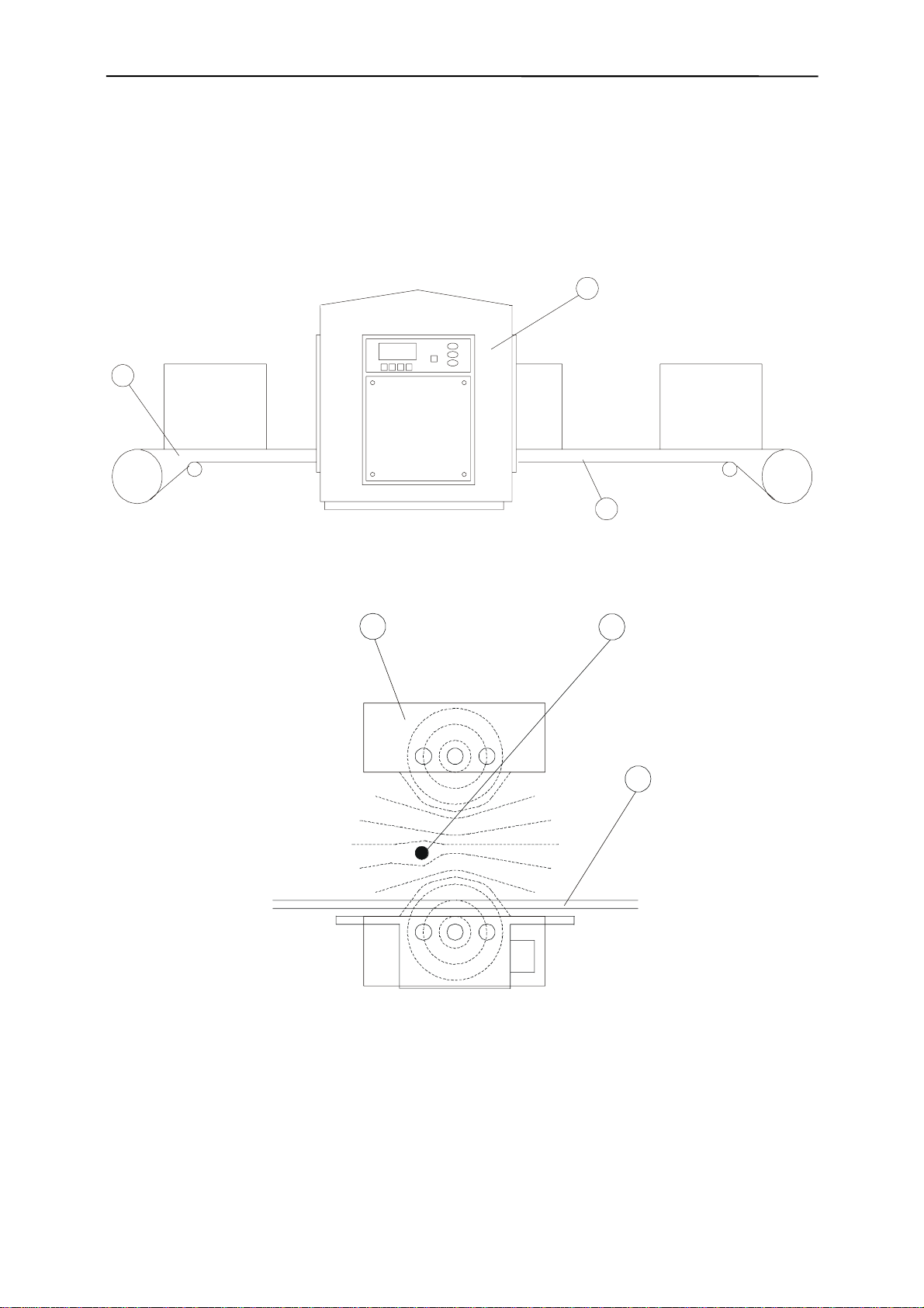
1.7 Overall view
6
2. Design and method of operation
2 Design and method operation
2.1 Functional principle
The material to be inspected (bulk or lump material) passes the detector head (2) on a belt conveyor
(1). The lower part of the belt can be put also through the detector head (3).
1
2
3
The material is penetrated within the aperture of the detector head by a high frequency electro-
magnetic field, which is generated by the control unit and the transmitter coil. Two identical voltages
are induced into the receiver coils, and are subtracted to zero if the system is in balance.
1
24
E
E
2
2
S
S
E
E
1
1
A metallic impurity (4) causes an unbalanced condition that generates a signal at the receiver. The
control unit processes this signal and triggers an output relay (see operational manual).
7

2. Design and method of operation
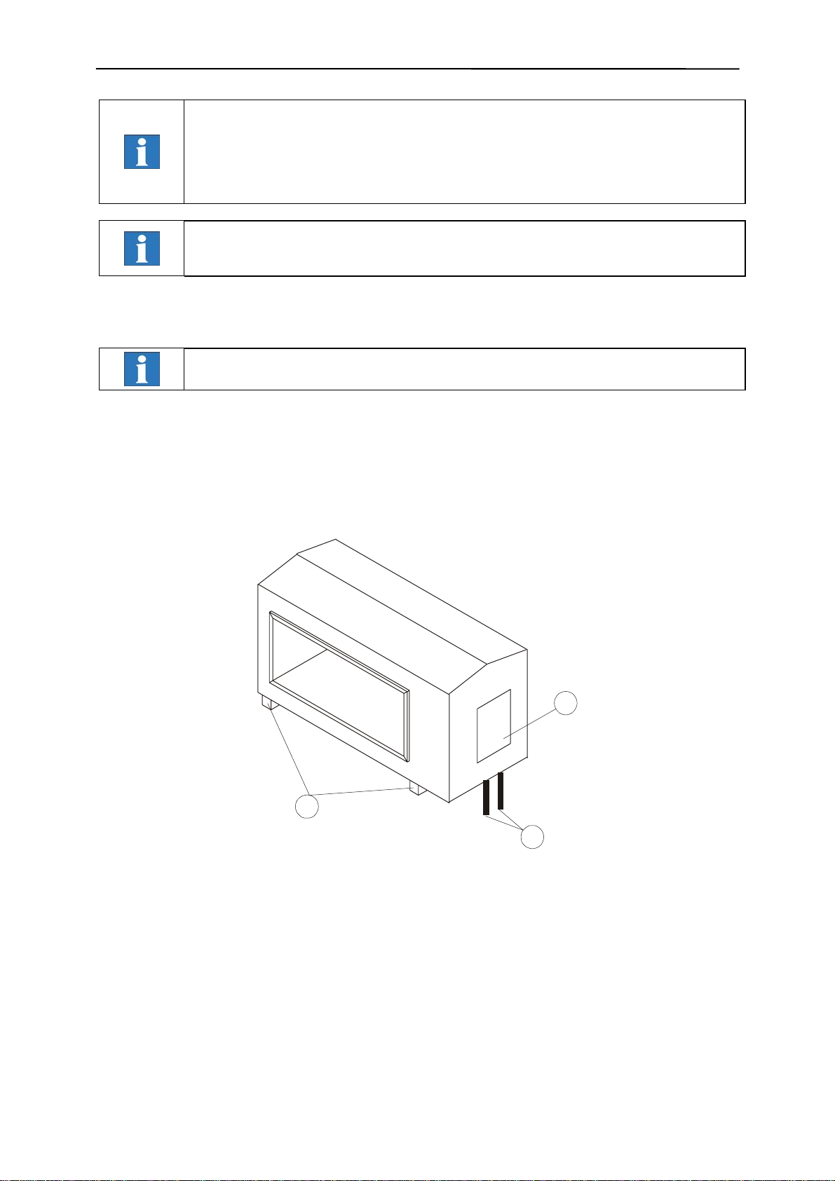
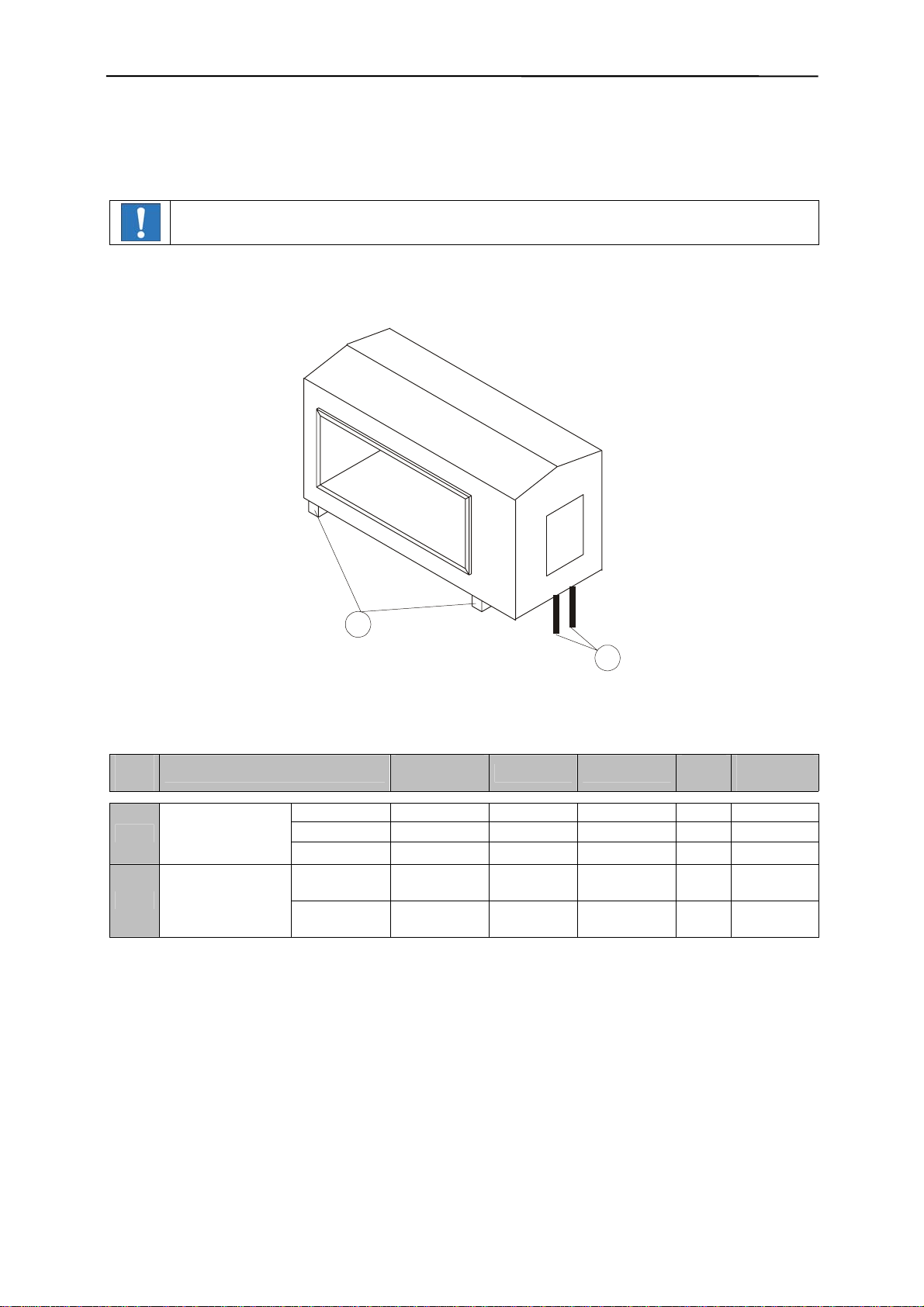
2.2 Functional elements
1
2
3
4
(1) Mounting elements for installation
(2) Coil connection box
(3) Connection cable for electronic unit
Options:
(4) Signalling device
2.3 Combination scopes
Different Control units can be used to control the detector head:
GENIUS+, PRIMUS or SENSITY.
8

3. Dimensions and technical data
3 Dimensions and technical data
3.1 Technical data sheet, see annex
3.2 Interfaces, see technical data sheet in the annex
3.3 Environmental conditions for operation, storage, and transport
The environment of the metal detector should be free of vibrations, of other influencing magnetic
fields, of chemical vapours such as softeners, chlorine, and similar substances. The metal detector
must not be exposed to direct sunlight. For the ambient temperature range please refer to the techni-
cal data sheet in the annex.
3.4 Noise levels
Sound pressure level measurements (in acc. with DIN 45 635)
Peak value of sound pressure level at distance of 1m from machine surface and 1.60m across the
floor, LpA, 1m, max.
Result:
Idling < 70 dB
Activated < 90 dB
Option signal horn or signal combination:
Activated < 105 dB
We reserve the right to change the contents due to product innovation or technical improve-
ment.
9

4. Safety
4 Safety
S+S equipment conforms with all official technical safety regulations. However, as a manufacturer we
believe it is our duty to make you aware of the following information.
The following safety and danger notes are intended for your protection, for the protection of
third parties, and for the protection of the equipment. The safety notes therefore should
always be observed! Please also observe the chapter on safety in the operating instruc-
tions of the control unit!
4.1 Use to the intended purpose
The intended purpose of the metal detector is the inspection of bulk or lump materials con-
veyed on belt conveyors, chutes or vibratory feeders with either the control unit GENIUS+,
PRIMUS or SENSITY. The metal detector system can be used for plastics, food, feed stuff,
chemical or recycling industry. The metal detector has to be fastened properly and stable.
At the operation field of the device, no steam (e.g. plasticizer) or other substances may
occur that attack cord insulation of PVC. Basically it is possible to also use the system in
other applications than the intended use stated herein, but such applications always require
the prior consultation and approval of S+S Separation and Sorting Technology GmbH.
4.2 Dangers arising from non-compliance with safety notes
Any non-observance of safety notes constitutes a danger for life and health.
4.3 Safety notes for the operator
The metal detector may only be operated in the intended purpose and in a perfect function-
ing condition. Particularly the covers of the detector connection boxes must be closed dur-
ing operation The operating instructions always have to be in a legible condition and com-
plete available. Ensure that up to date accident prevention procedures are in force prior to
commissioning. The operator may only appoint qualified personnel for operation, mainte-
nance and repair work. The electromagnetic field may cause malfunction of implants or may
affect health. People carrying implants, ie. heart pacemaker, should keep sufficient distance
to the detector head.
4.4 Safety notes during operating, maintenance and cleaning
Before opening the receiver and transmitter connection boxes remove dirt and moisture to
avoid them to get into the inside. Disconnect all power supplies or other connected circuits
Ingressed moisture must be removed.
In case of repairs of pc boards do not touch components or conducting paths with metallic
objects to avoid short circuits. Only qualified personnel should operate, maintain and re-
pair the equipment.
Signalling device option:
Always make sure that the electronics unit is not energised with mains or exter-
nal voltage before exchanging signalling elements!
4.5 Safety information for commissioning
When mounting the detector head there a risk of injury due to the weight of it.
Use suitable lifting gears for transportation.
Remove the lifting gear only after safe mounting.
If during installation the cable to the control unit has to be reconnected first close the
receiver/transmitter boxes before power up the system.
Please observe the information in 5.1 and 5.2.
10
4. Safety
4.6 Safety information for storage and transport
Always observe the information in paragraph 9 to avoid any transport damage and per-
sonal injuries.
4.7 Notes on residual risks
Electrical circuits may still be live even after having been isolated from the mains.
Switch off immediately if a fault occurs.
4.8 Notes on stable standing requirements
To avoid any loss of stable standing, the information for transport, commissioning and
operation must always be observed. Particularly take care that the detector head is bolted
4.9 Consequences of unauthorized modification
In case of unauthorized modification or repair work all the declarations and guarantees
given by the manufacturer will become void.
4.10 Inadmissible operation
For other applications as enumerated in 4.1 the GLS metal detector is not intended for –
that is regarded as inadmissible operation.
Inadmissible is the operation out of the specifications given in the technical data and the
operation under high mechanical static or dynamic loads (e.g. heavy system parts or
strong vibrations). Al It is furthermore not permitted to inspect any aggressive materials on
the conveyor, such as materials containing lyes, acids, and solvents, or materials that
react to electromagnetic fields, or living persons or animals.
It is not permitted to operate the metal detector in hazardous locations (explosion zones 0,
1, 20 und 21).
11

5. Commissioning
5 Commissioning
5.1 Mechanical installation
Use only enough stable lifting harnesses for big and heavy
detector heads.
Take care for a stable and vibrationproof mounting!
MZ
Metal-free zone must be strictly observed!
Within the metal-free zone no metallic parts must be situated.
For moving metal parts (pusher) the metal-free zone extends.
The dimensions of the metal-free zone are given in the at-
tached data sheet.
A nonmetallic slide (plastics or wood) must be used within
the aperture as a belt support.
The sliding board and also the run back belt underneath
should not touch the shaft walls inside of the detector
head opening.
The recommended gap between slide and detector is min.
10 mm.
Do not mount or operate the detector near sources of interferences (electric motors,
frequency and current converters). The required distance depends on the aperture size
of the detector head and the power of the source of interference.
12
5. Commissioning
Control unit mounted apart of the detector head:
Changes of the connection cables between the detector head GLS and the control unit
must be reconfirmed by S+S. Only original cables must be used
otherwise the CE-certification become unvalid.
The connections cable must be installed separate from other power and control lines
and carefully fixed or layed into a cable duct.
Installation of more then one GLS-coil:
In case that two or more GLS-coils are working in adjacent lines interferences can occur.
Therefore you need to reconfirm S+S.
Pay attention to the following order when mounting the GLS to conveying pipe:
Do not remove the plastic bars or replace them by other materials. This parts are not
only used as fastening elements but also as an electrical insulator.
1. If necessary disconnect the connection cable (3) (see also 5.2).
2. Put the belt and sliding board through the detector opening. Fasten the board and make sure that
neither the sliding board nor the belt touches the shaft walls inside of the detector opening.
3. For mounting the detector head use only the plastic bars.
4. Connect connector cable (3) according to picture 5.2.
1
2
3
13
5. Commissioning
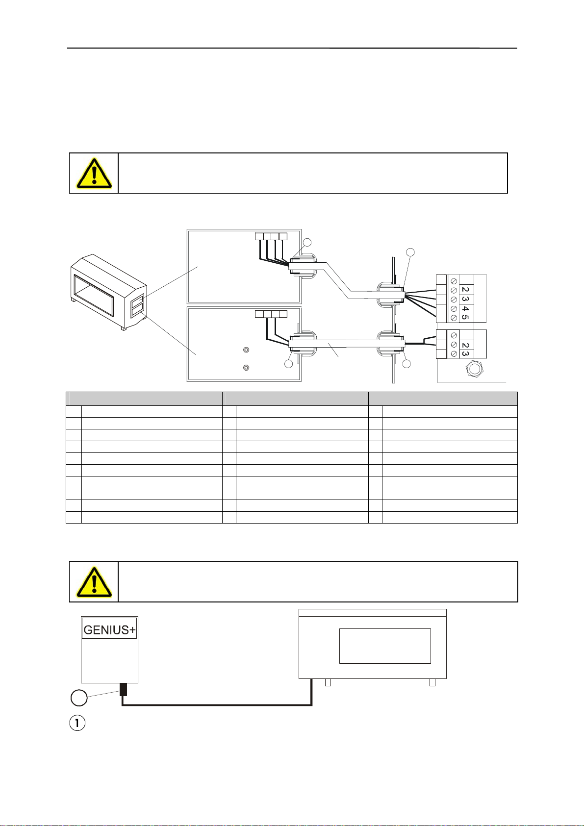
5.2 Connections
If the connection cable between detector head and control unit has been removed reconnect it accord-
ing to the sketch:
5.2.1 Control Unit PRIMUS / SENSITY
Electrical work should only be carried out by qualified personnel.
Before removing cover plates etc make sure the equipment is isolated from mains or
external voltage.
GLS metal detector Coil connection boxes Housing Control Unit
PRIMUS / SENSITY
Triax-Cable
11
Transmitter
Receiver
Receiver
Transmitter
1234
5678
9 9
9
9
Terminal coil connection box Connector receiver Connector transmitter
1 -----
1 white / brown 2 white / brown
2 2 x black (shield inside) 3 2 x black (shield inside)
3 yellow 4 yellow
4 green 5 green
5 -----
6 transparent 1 transparent
7 blue 2 blue
8 ----- 3 -----
9 shield outside
5.2.2 Control Unit GENIUS+
Electrical work should only be carried out by qualified personnel.
Before removing cover plates etc make sure the equipment is isolated from mains or ex-
ternal voltage.
GLS
1
Connector
The connection cable for control unit Genius+ and detector head can be plugged.
14

6. Errors and fault rectification
6 Errors and fault rectification
If you should have any questions, or if there should be any malfunctions, please contact
the manufacturer.
If you have any questions, please state the equipment type and serial number!
Service telephone: +49 (0) 85 54 - 30 8-180
15

7. Maintenance and cleaning
7 Maintenance and cleaning
Prior to any maintenance and cleaning work, disconnect the device from the mains
supply.
7.1 Maintenance
Although the GLS is maintenance-free, it is useful to check the equipment periodically:
- Check for loose bolts or nuts at the plastic bars
- Remove any objects laying on the detector head
- Remove any objects in the detector passage between slide and detector (remains of bulky goods
or accumulated dust)
- Check the throughput opening for damages and cracks, where water can enter?
- Check the connection cable for damages (i.e. the cable sheath).
7.2 Cleaning
7.2.1 Advice
- Please ensure you follow the instructions below.
- Specific machine components must be cleaned with specific substances. Please use the correct
materials and clean at regular intervals as suggested.
- Do not start cleaning until the machine has been switched off at the mains.
- If the building is being cleaned ensure the machines are covered up.
The following must not be used for cleaning:
- Sharp, hard or pointed objects
- Water or steam jet appliances
- Compressed air
- Hazardous and solvent-containing materials
- Cleaning agents that may attack the materials used
7.2.2 Cleaning instructions
We recommend cleaning the area with a soft, non-fibrous cloth using warm water and the appropriate
cleaning agent. Once weekly clean inside and underneath the detector thoroughly to remove dirt and
deposits. After cleaning wipe up any remaining drops of water with a dry, non-fibrous cloth. From time
to time apply oil to the stainless steel framework (eg Nirostol 55 cleaning and maintenance oil which
meets food industry standards).
7.2.3 are advice for stainless steel
The manufacturer uses only high-grade stainless steel. To prevent rust on the high-grade steel parts
do not use substances containing chloride (eg cleaning or disinfecting products) or site the machine in
an atmosphere containing chloride. If this is unavoidable the steel parts must be thoroughly rubbed
down immediately afterwards with cleaning oil eg Nirostol 55 cleaning and maintenance oil (which
meets food industry standards).
Important information for stainless steel models
Stainless steel models are extremely weatherproof and are therefore able to withstand most environ-
mental conditions.
However, even stainless steel can be susceptible to a slight film of rust.
These deposits are caused by contact corrosion and can be removed by following the instructions
below:
- Use a stainless steel cleaner: in principle any stainless steel cleaner may be used. Please ensure
you read the instructions prior to use.
- Use only cleaning agents that are halogen-free (ie without chlorides and fluorides), and salt and
hydrofluoric acid free.
- After each cleaning rinse the machine thoroughly with tap water
- Do not use the following: non-alloy materials or substances, abrasive cloths, cleaning agents con-
taining salt or hydrofluoric acid, chrome, silver or brass cleaners.
16
8. Spare parts
8 Spare parts
If you should have any questions please state equipment type and serial number!
Spare parts and wearing parts must always be obtained from the manufacturer of from a
supplier that is certified by the manufacturer.
8.1 Spare parts drawing
1
2
8.2 Spare parts list
Item
No. Part Drawing
no. Material Part No. Sp/
Con+ Article
no.
for DH<350 Z0007315 polyamide 77008033 Sp 84799080
for DH≥350 Z0010960 polyamide 77021768 Sp 84799080
1
Mounting ele-
ments for instal-
lation for DH≥700 on request polyamide on request Sp 84799080
Receiver
cable
44005410 Sp 85444290
2 Electronic con-
nection cable 1) Transmitter
cable 04015444 Sp 85444290
*Sp/Con = Spare part / Consumable
1) Please state the cable length when ordering!
17

9. Shipping, preservation, waste disposal, transport, storage
9 Shipping, preservation, waste disposal, transport, storage
9.1 Shipping, preservation, waste disposal
1. Choose packing that is suitable for the type and size of unit, taking into account
whether the shipment is for export by sea or airfreight, or for national or international
road transport The packing material must protect the goods from all damage under
normal transport conditions.
2. Depending on the size, weight and nature of the goods packing in cardboard boxes,
boxed pallets etc is only suitable for road transport.
Use reinforced card, corrugated cardboard, blister packing and shredded paper to fill
and protect the goods.
Electrostatic sensitive components (electronic boards, electronic modules, etc.) must
be packed in antistatic foil or foil bags prior to packing! (this is essential!)
Stick additional warning labels on the outside of the packaging eg “Attention, elec-
tronic equipment, do not drop,” etc. The packing should be sealed with adhesive tape
and, where the weight exceeds 50 kg, additionally with wrapping tape.
2a. When packing for international road transport use the instructions above (see point
2). Larger and heavier shipments must also be protected as for export in wooden
crates. Care must be taken to ensure that the goods inside the packing are protected
against corrosion.
Any parts that will corrode easily must be wrapped in oil paper or corrosion-protective
foil. Care must be taken to prevent the components moving around within the pack-
aging.
2b. International air freight shipments must be packed in wooden crates or on export
paltainers.
Care must be taken that the goods are secure and well-protected inside the packing.
Any parts liable to corrode must be wrapped in oil paper, protective foil or sprayed
with anti-corrosion spray.
2c. Sea-freight must be packed in seaworthy export crates. These crates can be ob-
tained from specialist suppliers.
The crates must be lined with oil paper to make them resistant to sea water and pre-
vent corrosion. In addition the goods must be protected against corrosion by use of a
spray or be wrapping in protective foil.
Care must be taken to ensure that the goods cannot move around inside the crate.
After packing the sea-freight crates must be properly closed.
The sea crates must also be fastened externally with securing tapes.
During loading care must be taken not to damage the external packaging.
The carrier must certify that the shipment has been accepted and loaded correctly by
detailing this on the bill of lading, loading list etc.
3.
Waste disposal: Observe the national waste disposal regulations.
18
9. Shipping, preservation, waste disposal, transport, storage
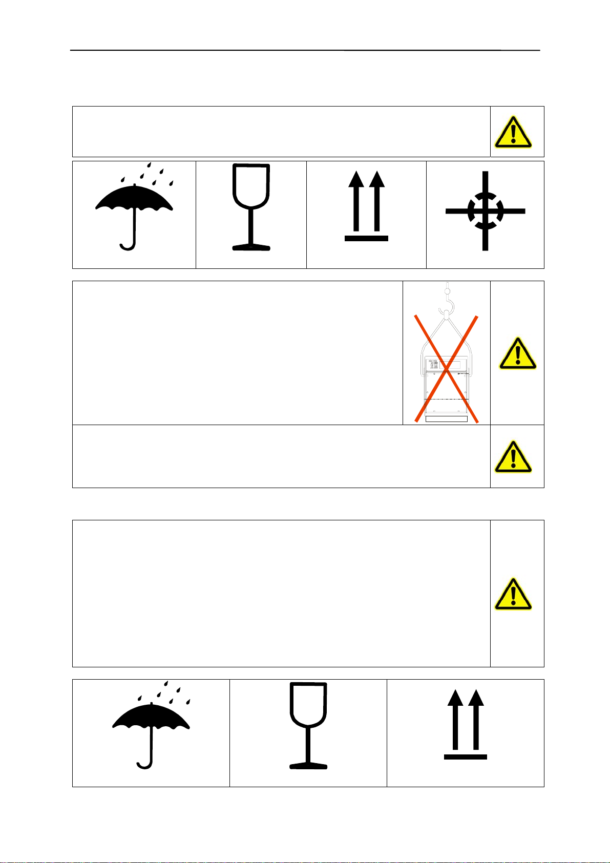
9.2 Transport
• In order to avoid injury or damage to the unit it must be handled properly. In addition to
following the instructions below, general health and safety good practice and specific
accident prevention guidelines should be observed.
• For correct handling and storage comply with the following symbols:
Protect against moisture
Careful: glass
Up
Centre of gravity
• Do not lift the metal detector head at the through put opening.
• Use a lifting gear attached to the mounting brackets or lifting eyes.
• Do not compress the side walls of the unit or any attached parts by pulling obliquely on
ropes or chains.
• Only remove handling safeguards once all installation work has been completed.
• When handling in a loading area make sure the unit cannot topple over or slip.
• Damage caused during transportation must always be reported to the manufacturer.
9.3 Storage
• If possible the unit should be stored in a closed room until final installation.
• If the unit is stored in the open it must be covered over with tarpaulins and open un-
derneath, to allow condensation to drain off.
• Avoid any higher temperature fluctuations. It is possible that condensed water that has
formed in the packing cannot properly drain and may corrode equipment surfaces. If a
formation of condensed water cannot be avoided, suitable desiccants e.g. in the form
of bags must be placed in the packing.
• If the unit has been packed for transportation by sea the packaging must not be dam-
aged or opened during transit and storage.
• For storage temperature and permissible air humidity please refer to the technical data
sheet.
• For correct storage comply with all storage and handling symbols:
Protect against moisture
Careful: glass
Up
19

10. Annex
10 Annex
• Technical data sheet
• Installation suggestions for tunnel metal detectors
• Circuit diagrams, wiring diagrams, etc.
• Signalling device (option) operating instructions
20
Table of contents
Popular Metal Detector manuals by other brands


Kellyco
Kellyco Minelab X-Terra Quick start referen

Waldbeck
Waldbeck Yukon instruction manual

DeepTech
DeepTech Vista MINI instruction manual

Fisher Research Labs
Fisher Research Labs Gemini-3 operating manual

Quest Engineering
Quest Engineering V60 instruction manual

Minelab
Minelab PRO-FIND 25 Instruction guide