S+S HYGRASREG TW-W Repair manual
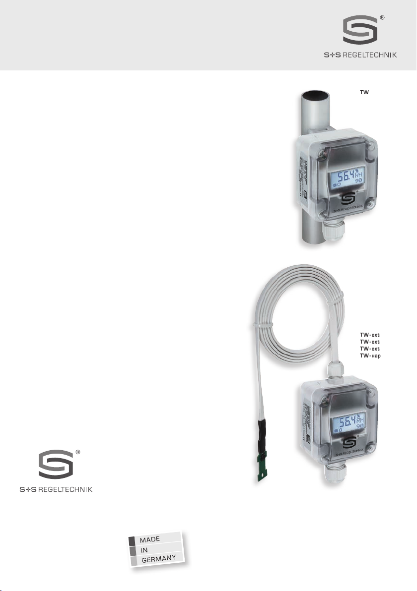
HYGRASREG® TW
D G F r
Herzlichen Glückwunsch!
Sie haben ein deutsches Qualitätsprodukt erworben.
Congratulations!
You have bought a German quality product.
Félicitations!
Vous avez fait l’acquisition d’un produit allemand de qualité.
Примите наши поздравления !
Вы приобрели качественный продукт, изготовленный в Германии.
D
Bedienungs- und Montageanleitung
Taupunktwächter,
incl. Spannband ⁄ mit abgesetztem Fühlerkopf,
mit aktivem ⁄ schaltendem Ausgang
G
Operating Instructions, Mounting & Installation
Dew point control switches
including strap ⁄ with detached sensor head,
with active ⁄ switching outputs
F
Notice d’instruction
Contrôleur de point de rosée,
y compris collier de serrage ou avec sonde déportée,
avec sortie active ⁄ en tout ou rien
r
Руководство по монтажу и обслуживанию
Реле контроля точки росы,
вкл. хомут ⁄ с вынесенной чувствительной головкой,
с активным ⁄ релейным выходом
TW - extern
TW - external
TW - externe
TW - наружный
TW
6003-2900-2015-000 32900-2017 V101 12 ⁄ 2016
S+S REGELTECHNIK GMBH
PIRNAER STRASSE 20
90411 NÜRNBERG ⁄GERMANY
FON +49 (0) 911 ⁄ 519 47-0
FAX +49 (0) 911 ⁄ 519 47-70
www.SplusS.de
HYGRASREG® TW
D G F r
TW
~107
72
64
15
9
10
30
10
54
14.8
43.3
M16x1.5
~107
72
~107
72
64
15
9
10
30
10
54
14.8
43.3
M16x1.5
~107
72
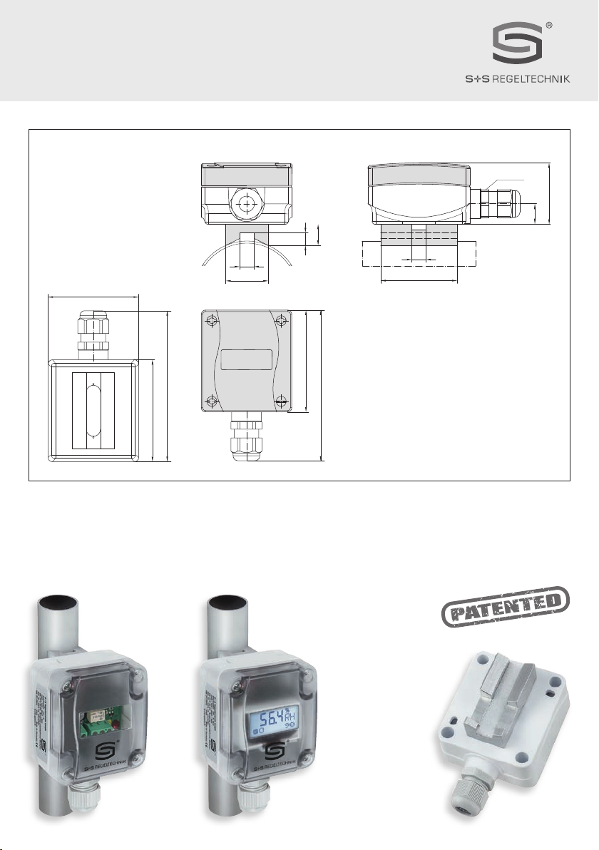
Maßzeichnung
Dimensional drawing
Plan coté
Габаритный чертеж
TW
prodynamische Querkonvektion
pro-dynamic cross convection
convection transversale prodynamique
Высокоэффективная поперечная конвекция
TW
mit Spannband zur direkten Rohrmontage
including strap for installation directly on pipes
y compris collier de serrage pour montage direct sur tube
с хомутом непосредственный монтаж на трубах

DHYGRASREG®TW
Rev. 2017 - V15 DE
Patentiertes Qualitätsprodukt (prodynamische Querkonvektion Patent-Nr. DE10 2012 015 726.6)
Der Taupunktwächter
HYGRASREG
®
TW
wird auf Kühl- ⁄ Kaltwasserleitungen oder auf kühlen Flächen montiert. Er erfasst die Betauung zuverlässig
mit seinem Feuchte- und Temperatursensor (keine Leitfähigkeitsmessung)
und liefert aufgrund
seiner patentierten Messmethode, der
prodynami-
schen Querkonvektion
,
ein exaktes Messergebnis (mit LED-Statusanzeige),
wahlweise mit ⁄ ohne Display
.
Die Taupunkttemperatur ist die Temperatur,
bei der die Luft den Sättigungszustand erreicht und Wasser zu kondensieren beginnt. Durch den stetigen Messbereich von 0...100 % r.H. beim
TW-U
und einstellbarem Schaltpunkt beim
TW-W
von 75...100 % r.H., können z.B. Kühldecken so betrieben werden, dass vor der Betauung der Rohre oder
Kühldecken bzw. des zu überwachenden Objektes der Schaltausgang des Taupunktwächters, der DDC aktiviert wird, dadurch z.B. die Heizung oder
andere Stellglieder zuschalten und somit eine Betauung verhindert wird.
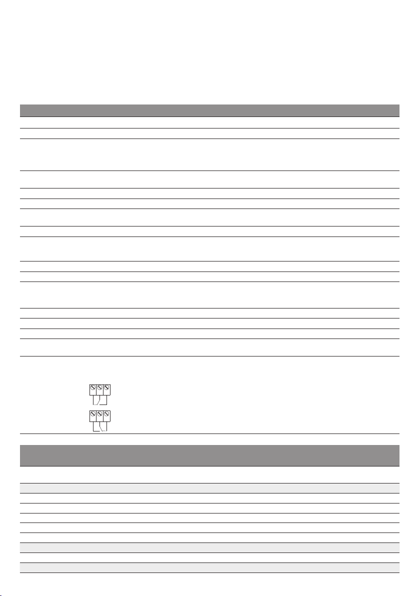
TECHNISCHE DATEN
Spannungsversorgung: 24 V AC (± 20 %) und 15...36 V DC
Leistungsaufnahme: < 1,1 VA ⁄ 24 V DC ; < 2,2 VA ⁄ 24 V AC
Messbereich: detektiert wird die Betauung
0...100 % r.H. beim
TW-U
, stetig
75...100 % r. H. beim
TW-W
, schaltend
(Schaltpunkt über Potentiometer einstellbar, Auslieferungszustand 75 % r.H.)
Sensoren:
digitaler Feuchtesensor mit integriertem Temperatursensor,
kleine Hysterese, hohe Langzeitstabilität
Sensorschutz: Membranfilter
Ausgangssignal: 0-10 V oder potentialfreier Wechsler (24 V), 1 A ohmsche Last
Prozessanschluss: Endlosspannband mit Schloss aus Metall, 300 mm, für Rohre bis 3 ''
(ist im Lieferumfang enthalten)
elektrischer Anschluss: 0,14 - 1,5 mm², über Schraubklemmen
Gehäuse: aus Kunststoff, Werkstoff Polyamid, 30 % glaskugelverstärkt,
mit Schnellverschlussschrauben (Schlitz ⁄ Kreuzschlitz -Kombination),
Farbe Verkehrsweiß (ähnlich RAL 9016), Deckel ist transparent!
Abmaße Gehäuse: 72 x 64 x 43,3 mm (Tyr 1)
Kabelverschraubung: M 16x 1,5 ; mit Zugentlastung, auswechselbar, max. Innendurchmesser 10,4 mm
Montage:
TW
mit Spannband zur direkten Rohrmontage
oder zur direkten Montage auf geraden Oberflächen (z.B. Wänden, Decken)
TW - extern
mit abgesetztem Fühlerkopf (Kabellänge KL = 1,5 m) zur Rohrmontage
Schutzklasse: III (nach EN 60 730)
Schutzart: IP 65 (nach EN 60 529)
Normen: CE-Konformität, elektromagnetische Verträglichkeit nach EN 61326, EMV-Richtlinie 2014 ⁄ 30 ⁄ EU
Optional:
Display mit Beleuchtung,
zweizeilig, Ausschnitt ca. 36 x15 mm (B x H),
zur Anzeige der Ist-Feuchte und des SchaltzustandsdesRelais
FUNKTION
Der Relaisausgang ist angesteuert (Kontakt 13-11 geschlossen)
bei Unterschreitung des
eingestellten Schaltpunkts
(Auslieferungszustand 75 % r.H.) und
öffnet (Kontakt 12-11 geschlossen) im Fehlerfall (Netzausfall, Kondensation).
LED kurze Impulse =
Relais aktiv → Schaltpunkt unterschritten
IST-Feuchte
< eingestellter Schaltpunkt (nicht betaut)
LED lange Impulse =
Relais inaktiv → Schaltpunkt überschritten
IST-Feuchte
> eingestellter Schaltpunkt (betaut)
HYGRASREG
®
TW
– Taupunktwächter, incl. Spannband (± 3 %), Deluxe
HYGRASREG
®
TW - extern
– Taupunktwächter, mit abgesetztem Fühlerkopf (± 3 %), Deluxe
Typ ⁄ WG01 Messbereich
Feuchte
Ausgang
Feuchte
Montageart Display Art.-Nr.
TW Sensor intern
TW-W 75...100 % r. H. Wechsler zur direkten Rohrmontage 1202-1015-0001-000
TW-W DISPLAY 75...100 % r. H. Wechsler zur direkten Rohrmontage ■1202-1015-1201-020
TW-U 0...100 % r. H. 0 -10 V zur direkten Rohrmontage 1201-1011-1001-020
TW-U/W 0...100 % r. H. 0 -10 V + Wechsler zur direkten Rohrmontage 1202-1012-1001-020
TW-U/W DISPLAY 0...100 % r. H. 0 -10 V + Wechsler zur direkten Rohrmontage ■1202-1012-1201-020
TW - extern Sensor extern
TW-W EXTERN 75...100 % r. H. Wechsler zur Rohrmontage 1202-1015-0021-030
Aufpreis:
Display mit Beleuchtung,
zweizeilig
13 11 12
13 11 12

DMontage und Installation
Rev. 2017 - V15 DE
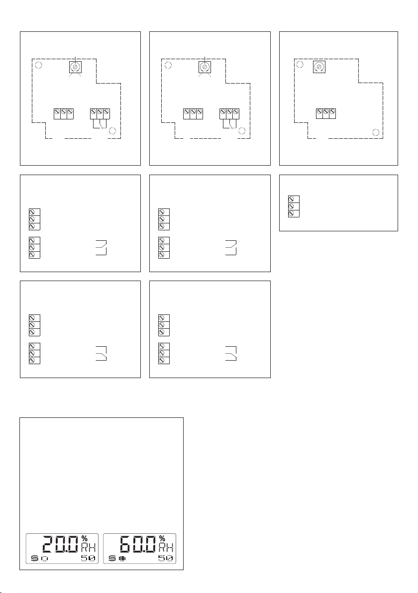
ANZEIGE IM DISPLAY
Standardmäßig wird im Display in der ersten Zeile
die
relative Feuchte
angezeigt.
In der zweiten Zeile ist links die Information
zum
Schaltzustand der Relais
(als Kreis) sichtbar,
sowie rechts der jeweilige
Schaltwert
in % r. H.
(Schaltpunkt über Potentiometer einstellbar,
Auslieferungszustand 75 % r.H.).
○
Kreis, leer
= Relais im Ruhestand
●
Kreis, voll
= Relais angezogen
Anschlussbild
TW - U
1
2
3
GND
UB+ Versorgungsspannung 24V AC/DC
Ausgang Betauung 0-10 V (stetig)
1
2
3
13
11
12
GND
Schliesser
(nicht betaut)
Öffner
(betaut)
UB+ Versorgungsspannung 24V AC/DC
Wechsler
(24 V)
Ausgang Betauung 0-10 V (stetig)
1
2
3
13
11
12
frei
GND
Schliesser
(nicht betaut)
Öffner
(betaut)
UB+ Versorgungsspannung 24V AC/DC
Wechsler
(24 V)
Anschlussbild
(betaut)
r. H.
>
Schaltpunkt
Anschlussbild
(betaut)
r. H.
>
Schaltpunkt
TW - UW TW - W
1
2
3
13
11
12
Ausgang Betauung 0-10 V (stetig)
GND
Schliesser
(nicht betaut)
Öffner
(betaut)
UB+ Versorgungsspannung 24V AC/DC
Wechsler
(24 V)
1
2
3
13
11
12
frei
GND
Schliesser
(nicht betaut)
Öffner
(betaut)
UB+ Versorgungsspannung 24V AC/DC
Wechsler
(24 V)
Anschlussbild
(nicht betaut)
r. H.
<
Schaltpunkt
Anschlussbild
(nicht betaut)
r. H.
<
Schaltpunkt
TW - UW TW - W
1 2 3
max.
+
min.
–
Offset ±10%
GND
UB+ 24V AC/DC
Ausgang Betauung
0-10V
13 11 121 2 3
max.
100%
87,5%
min.
75%
(default)
Schliesser
Öffner
UB+ 24V AC/DC
frei
GND
Potentiometer
Einstellung
Schaltpunkt
75%...100% r.H.
13 11 121 2 3
max.
100%
min.
75%
(default)
87,5%
Potentiometer
Einstellung
Schaltpunkt
75%...100% r.H.
Schliesser
Öffner
GND
UB+ 24V AC/DC
Ausgang Betauung
0-10V
Schaltbild
TW - W
Schaltbild
TW - UW
Schaltbild
TW - U

DWichtige Hinweise
– Dieses Gerät darf nur in schadstofffreier, nicht kondensierender Luft, ohne Über- oder Unterdruck am Sensorelement eingesetzt werden.
– Bei Aussen- und Kanalfühlern schützt der Sinterfilter des Sensorelementes den Feuchtesensor vor eventuellen Staubbelastungen.
Dieser Filter sollte bei Verunreinigung ⁄ Verschmutzung regelmäßig gewartet werden.
– Staub- und Verunreinigungen verfälschen das Messergebnis und sind zu vermeiden.
Geringe Verunreinigungen und Staubablagerungen können mit Druckluft beseitigt werden.
– Das Berühren des Feuchteelementes ist unbedingt zu vermeiden, da dies zu erheblichen Fehlmessungen führt.
– Bei Verunreinigungen empfehlen wir eine werksseitige Reinigung und Neukalibrieung.
– Chemikalien oder andere Reinigungsmittel dürfen unter keinen Umständen auf den Sensor gelangen.
– Die relative Feuchte von 0 ...100 % wird durch das Ausgangssignal von 0 -10 V abgebildet. Der Arbeitsbereich des Gerätes umfasst 10... 95 % r.H.,
ausserhalb dieses Bereiches kann es zu Fehlmessungen bzw. zu erhöhten Abweichungen kommen.
–
Beim Anschluss mehrerer Fühler (0 -10 V) an eine gemeinsame Spannungsversorgung mit 24V AC (Wechselspannung) ist auf die Polung zu achten, da
sonst die Wechselspannungsquelle kurz geschlossen werden kann. Die Spannungsausgänge sind kurzschlussfest, ein Anlegen einer Überspannung
oder der Spannungsversorgung am Spannungsausgang zerstört das Gerät.
– Beim Betrieb des Gerätes ausserhalb des Spezifikationsbereiches entfallen alle Garantieansprüche.
Als AGB gelten ausschließlich unsere sowie die gültigen „Allgemeinen Lieferbedingungen für Erzeugnisse und Leistungen der Elektroindustrie“
(ZVEI Bedingungen) zuzüglich der Ergänzungsklausel „Erweiterter Eigentumsvorbehalt“.
Außerdem sind folgende Punkte zu beachten:
– Vor der Installation und Inbetriebnahme ist diese Anleitung zu lesen und die alle darin gemachten Hinweise sind zu beachten!
– Der Anschluss der Geräte darf nur an Sicherheitskleinspannung und im spannungslosen Zustand erfolgen. Um Schäden und Fehler am Gerät
(z.B. durch Spannungsinduktion) zu verhindern, sind abgeschirmte Leitungen zu verwenden, eine Parallelverlegung zu stromführenden Leitungen zu
vermeiden und die EMV- Richtlinien zu beachten.
– Dieses Gerät ist nur für den angegebenen Verwendungszweck zu nutzen, dabei sind die entsprechenden Sicherheitsvorschriften des VDE,
der Länder, ihrer Überwachungsorgane, des TÜV und der örtlichen EVU zu beachten.
Der Käufer hat die Einhaltung der Bau- und Sicherungsbestimmung zu gewährleisten und Gefährdungen aller Art zu vermeiden.
– Für Mängel und Schäden, die durch unsachgemäße Verwendung dieses Gerätes entstehen, werden keinerlei Gewährleistungen und Haftungen
übernommen.
– Folgeschäden, welche durch Fehler an diesem Gerät entstehen, sind von der Gewährleistung und Haftung ausgeschlossen.
– Die Installation der Geräte darf nur durch Fachpersonal erfolgen.
– Es gelten ausschließlich die technischen Daten und Anschlussbedingungen der zum Gerät gelieferten Montage- und Bedienungsanleitung,
Abweichungen zur Katalogdarstellung sind nicht zusätzlich aufgeführt und im Sinne des technischen Fortschritts und der stetigen Verbesserung
unserer Produkte möglich.
– Bei Veränderungen der Geräte durch den Anwender entfallen alle Gewährleistungsansprüche.
– Dieses Gerät darf nicht in der Nähe von Wärmequellen (z.B. Heizkörpern) oder deren Wärmestrom eingesetzt werden, eine direkte Sonnen-
einstrahlung oder Wärmeeinstrahlung durch ähnliche Quellen (starke Leuchte, Halogenstrahler) ist unbedingt zu vermeiden.
– Der Betrieb in der Nähe von Geräten, welche nicht den EMV- Richtlinien entsprechen, kann zur Beeinflussung der Funktionsweise führen.
– Dieses Gerät darf nicht für Überwachungszwecke, welche dem Schutz von Personen gegen Gefährdung oder Verletzung dienen und
nicht als Not-Aus-Schalter an Anlagen und Maschinen oder vergleichbare sicherheitsrelevante Aufgaben verwendet werden.
– Die Gehäuse- und Gehäusezubehörmaße können geringe Toleranzen zu den Angaben dieser Anleitung aufweisen.
– Veränderungen dieser Unterlagen sind nicht gestattet.
– Reklamationen werden nur vollständig in Originalverpackung angenommen.
Vor der Installation und Inbetriebnahme ist diese Anleitung zu lesen und die alle darin gemachten Hinweise sind zu beachten!
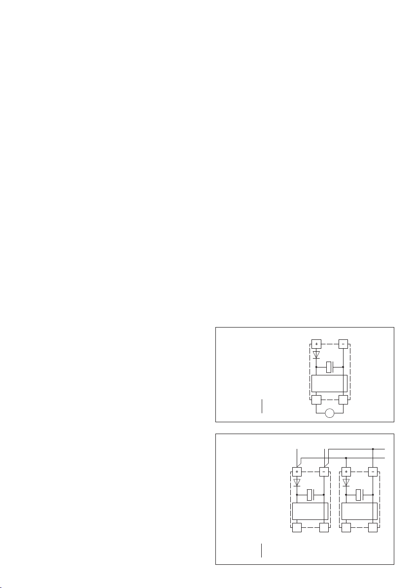
Schaltbild
Parallelbetrieb
Schaltbild
Einzelbetrieb
VERSORGUNGSSPANNUNG:
Als Verpolungsschutz der Betriebsspannung ist bei dieser Gerätevariante
eine Einweggleichrichtung bzw. Verpolungschutzdiode integriert. Diese
interne Einweggleichrichtung erlaubt auch den Betrieb mit AC-Versorgungs-
spannung bei 0 -10 V Geräten.
Das Ausgangssignal ist mit einem Messgerät abzugreifen. Hierbei wird die
Ausgangsspannung gegen das Nullpotenial (OV) der Eingangsspannung ge-
messen!
Wird dieses Gerät mit
DC- Versorgungsspannung
betrieben, ist der Be-
triebsspannungseingang UB+ für 15...36 V DC - Einspeisung und UB– bzw.
GND als Masseleitung zu verwenden!
Werden mehrere Geräte von einer 24 V
AC- Spannung
versorgt, ist
darauf zu achten, dass alle „positiven“ Betriebsspannungseingänge (+) der
Feldgeräte miteinander verbunden sind, sowie alle „negativen“ Betriebs-
spannungseingänge (–) = Bezugspotential miteinander verbunden sind (pha-
sengleicher Anschluss der Feldgeräte). Alle Feldgeräteausgänge müssen auf
das gleiche Potential bezogen werden!
Bei Verpolung der Versorgungsspannung an einem der Feldgeräte würde
über dieses ein Kurzschluss der Versorgungsspannung erzeugt. Der somit
über dieses Feldgerät fließende Kurzschlussstrom kann zur Beschädigung
dieses Gerätes führen.
Achten Sie daher auf die korrekte Verdrahtung!
Schaltung Schaltung
0-10V
0V/GND
0-10V
0V/GND
Versorgung mit
AC 24V~ 0V
DC 15-36V = GND
AC 24V~ 0V
DC 15-36V = GND
Schaltung
0-10V
0V/GND
V
Versorgung mit

GHYGRASREG®TW
Rev. 2017 - V15 GB
Patented quality product (pro-dynamic cross convection patent no. DE 10 2012 015 726.6)
The dew point control switch
HYGRASREG
®
TW
is installed on cooling ⁄ cold-water piping or on cooled surfaces. It reliably detects formation of dew
by means of its humidity and temperature sensor (no conductivity measurement)
and, thanks
to its patented measuring method,
pro-dynamic cross
convection
, yields an exact measurement result (with LED status display),
with ⁄ without display
. Dew point temperature is that temperature at
which air reaches the state of saturation and water vapour starts to condensate. Facilitated by the continuous measuring range from 0...100 % r.H.
of the
TW-U
and the adjustable switchpoint for the
TW-W
of 75...100 % r.H., it is possible to operate cooling ceilings, for example, so that the
switching output of the dew point control switch, the DDC, is activated and then triggers a heater or other control elements, thereby preventing the
formation of dew on pipes or cooling ceilings or on the property to be monitored.
TECHNICAL DATA
Power supply: 24 V AC (± 20 %) and 15...36 V DC
Power consumption: < 1.1 VA ⁄ 24 V DC; < 2.2VA ⁄ 24 V AC
Measuring Range: formation of dew is detected at
0...100 % r.H. on the
TW-U
, continuous
75...100 % r.H. on the
TW-W
, switching
(switchpoint adjustable by potentiometer, factory setting 75 % r.H.)
Sensors:
digital humidity sensor with integrated temperature sensor,
small hysteresis, high long-term stability
Sensor protection: membrane filter
Output signal: 0-10 V or potential-free changeover contact (24 V), 1 A ohmic load
Process connection: endless metal strap with metal tightener, 300 mm, for pipes up to 3 " diameter
(included in the scope of delivery)
Electrical connection: 0.14 - 1.5 mm², via terminal screws
Enclosure: plastic, material polyamide, 30 % glass-globe-reinforced,
with quick-locking screws (slotted ⁄ Phillips head combination),
colour traffic white (similar to RAL 9016), enclosure cover is transparent!
Enclosure dimensions: 72 x 64 x 43.3 mm (Tyr 1)
Cable gland: M 16x 1.5, including strain relief, exchangeable, max. inner diameter 10.4mm
Mounting:
TW
with strap for direct mounting on pipes or
for direct mounting on flat surfaces (e.g. walls, ceilings)
TW - external
with detached sensor head (cable length KL = 1.5 m) for mounting on pipes
Protection class: III (according to EN 60 730)
Protection type: IP 65 (according to EN 60 529)
Standards: CE conformity, electromagnetic compatibility according to EN 61 326, EMC directive 2014 ⁄ 30 ⁄ EU
Optional: two-line
display with illumination,
cutout approx. 36 x15 mm (W x H),
for displaying actual humidity and the switching status of the relay
FUNCTION
The relay output is triggered (contact 13-11 closed) if the
pre-set switchpoint
(factory setting 75 % r.H.)
is not reached and opens (contact 12 -11 closed) in the event of an error (power failure, condensation).
LED short pulses =
relay active → switchpoint not reached
ACTUAL humidity
< pre-set switchpoint (no condensation)
LED long pulses =
relay inactive → switchpoint exceeded
ACTUAL humidity
> pre-set switchpoint (condensation)
13 11 12
13 11 12
HYGRASREG
®
TW
– Dew point control switches including strap (± 3 %), Deluxe
HYGRASREG
®
TW - external
– Dew point control switches with detached sensor head (± 3 %), Deluxe
Type ⁄ WG01 Measuring Range
Humidity
Output
Humidity
Mounting Display Item No.
TW Sensor internal
TW-W 75...100 % r. H. Changeover contact for mounting directly on pipes 1202-1015-0001-000
TW-W DISPLAY 75...100 % r. H. Changeover contact for mounting directly on pipes ■1202-1015-1201-020
TW-U 0...100 % r. H. 0 -10 V for mounting directly on pipes 1201-1011-1001-020
TW-U/W 0...100 % r. H. 0 -10 V + Changeover contact for mounting directly on pipes 1202-1012-1001-020
TW-U/W DISPLAY 0...100 % r. H. 0 -10 V + Changeover contact for mounting directly on pipes ■1202-1012-1201-020
TW - external Sensor external
TW-W EXTERN 75...100 % r. H. Changeover contact for mounting on pipes 1202-1015-0021-030
Extra charge: Two-line
display with illumination
GMounting and Installation
Rev. 2017 - V15 GB
READOUT IN THE DISPLAY
By default, the first line of the display shows
the
relative humidity
.
The second line shows the information about
the
switching status of the relay
(as a circuit) on the left,
and the respective
switching value
in % r.H. on the right
(switchpoint adjustable by potentiometer,
factory setting 75 % r.H.).
○
Circuit, empty
= relay in idle state
●
Circuit, full
= relay energised
1 2 3
max.
+
min.
–
Offset ±10%
GND
UB+ 24V AC/DC
Output bedewing
0-10V
13 11 121 2 3
max.
100%
87,5%
min.
75%
(default)
Normally
open contact
Breaker
UB+ 24V AC/DC
free
GND
Potentiometer
Swithpoint
setting
75%...100% r.H.
13 11 121 2 3
max.
100%
min.
75%
(default)
87,5%
Normally
open contact
Breaker
GND
UB+ 24V AC/DC
Output bedewing
0-10V
Potentiometer
Swithpoint
setting
75%...100% r.H.
Schematic diagram
TW - W
Schematic diagram
TW - UW
Schematic diagram
TW - U
Connecting diagram
TW - U
1
2
3
GND
UB+ supply voltage 24V AC/DC
Output bedewing 0-10V (continuous)
1
2
3
13
11
12
GND
UB+ supply voltage 24V AC/DC
Normally open contact
(no dew)
Breaker
(dew)
changeover
(24 V)
Output bedewing 0-10V (continuous)
1
2
3
13
11
12
free
GND
UB+ supply voltage 24V AC/DC
Normally open contact
(no dew)
Breaker
(dew)
changeover
(24 V)
Connecting diagram
(condensation)
r.H.
>
switchpoint
Connecting diagram
(condensation)
r.H.
>
switchpoint
TW - UW TW - W
1
2
3
13
11
12
Output bedewing 0-10V (continuous)
GND
UB+ supply voltage 24V AC/DC
Normally open contact
(no dew)
Breaker
(dew)
changeover
(24 V)
1
2
3
13
11
12
free
GND
UB+ supply voltage 24V AC/DC
Normally open contact
(no dew)
Breaker
(dew)
changeover
(24 V)
Connecting diagram
(no condensation)
r.H.
<
switchpoint
Connecting diagram
(no condensation)
r.H.
<
switchpoint
TW - UW TW - W
GGeneral notes
– This device must only be used in non-precipitating air without above-atmospheric or below-atmospheric pressure at the sensor element.
– On outdoor and duct sensors, the sinter filter of the senor element protects the humidity sensor against potential dust exposure.
In case of pollution ⁄ contamination, this filter should be cleaned on a regular basis.
– Dust and pollution falsify measurement results and are to be avoided. Slight pollution and dust sediments can be removed by using compressed air.
– Touching the humidity element is under any circumstances to be avoided, as that would result in considerable mismeasurements.
– In case of pollution, we recommend cleaning and recalibration in the factory.
– In any case, the sensor must not get in contact with chemicals or other cleaning agents.
– The relative humidity of 0...100 % is indicated by an output signal of 0 -10 V or 4 ... 20 mA.
– The device operating range covers 10.0...99.9% r.H. Beyond that range, mismeasurements or increased deviations may occur.
– When several sensors (0 -10V) are connected to one voltage supply of 24 V AC, correct polarity must be regarded as otherwise the alternating
voltage source may be short-circuited.
– The voltage outputs are short-circuit proof. Applying overvoltage or voltage supply to the voltage output will destroy the device.
– If this device is operated beyond the specified range, all warranty claims are forfeited.
Our “General Terms and Conditions for Business“ together with the “General Conditions for the Supply of Products and Services of the Electrical and
Electronics Industry“ (ZVEI conditions) including supplementary clause “Extended Retention of Title“ apply as the exclusive terms and conditions.
In additionIn addition, the following points are to be observed:
– These instructions must be read before installation and putting in operation and all notes provided therein are to be regarded!
– Devices must only be connected to safety extra-low voltage and under dead-voltage condition. To avoid damages and errors the device (e.g. by
voltage induction) shielded cables are to be used, laying parallel with current-carrying lines is to be avoided, and EMC directives are to be observed.
– This device shall only be used for its intended purpose. Respective safety regulations issued by the VDE, the states, their control authorities, the
TÜV and the local energy supply company must be observed. The purchaser has to adhere to the building and safety regulations and has to prevent
perils of any kind.
– No warranties or liabilities will be assumed for defects and damages arising from improper use of this device.
– Consequential damages caused by a fault in this device are excluded from warranty or liability.
– These devices must be installed by authorised specialists only.
– The technical data and connecting conditions of the mounting and operating instructions delivered together with the device are exclusively valid.
Deviations from the catalogue representation are not explicitly mentioned and are possible in terms of technical progress and continuous improve-
ment of our products.
– In case of any modifications made by the user, all warranty claims are forfeited.
– This device must not be installed close to heat sources (e.g. radiators) or be exposed to their heat flow.
Direct sun irradiation or heat irradiation by similar sources (powerful lamps, halogen spotlights) must absolutely be avoided.
– Operating this device close to other devices that do not comply with EMC directives may influence functionality.
– This device must not be used for monitoring applications, which serve the purpose of protecting persons against hazards or injury,
or as an EMERGENCY STOP switch for systems or machinery, or for any other similar safety-relevant purposes.
– Dimensions of enclosures or enclosure accessories may show slight tolerances on the specifications provided in these instructions.
– Modifications of these records are not permitted.
– In case of a complaint, only complete devices returned in original packing will be accepted.
These instructions must be read before installation and putting in operation and all notes provided therein are to be regarded!
Connecting scheme
Parallel operation
Connecting scheme
Individual operation
SUPPLY VOLTAGE:
For operating voltage reverse polarity protection, a one-way rectifier or
reverse polarity protection diode is integrated in this device variant.
This internal one-way rectifier also allows operating 0 - 10V devices on AC
supply voltage.
The output signal is to be tapped by a measuring instrument. Output volt-
age is measured against zero potential (O V) of the input voltage!
When this device is operated on
DC supply voltage
, the operating voltage
input UB+ is to be used for 15...36 V DC supply and UB – or GND for ground
wire!
When several devices are supplied by one 24 V
AC voltage supply
, it is to
be ensured that all ”positive“ operating voltage input terminals (+) of the
field devices are connected with each other and all ”negative“ operating
voltage input terminals (–) (= reference potential) are connected together
(in-phase connection of field devices). All outputs of field devices must be
referenced to the same potential!
In case of reversed polarity at one field device, a supply voltage short-
circuit would be caused by that device. The consequential short-circuit
current flowing through this field device may cause damage to it.
Therefore, pay attention to correct wiring!
Circuitry Circuitry
0...10V
0V/GND
0...10V
0V/GND
Power supply
AC 24V~ 0V
DC 15-36V = GND
Circuitry
0...10V
0V/GND
V
Power supply
AC 24V~ 0V
DC 15-36V = GND
FHYGRASREG®TW
Rev. 2017 - V15 FR
Produit de qualité breveté (convection transversale prodynamique, n° de brevet DE 10 2012 015 726.6)
Le contrôleur de point de rosée
HYGRASREG
®
TW
est monté sur des plafonds frigorifiques et des conduites frigorifiques ⁄ d'eau froides ou des
surfaces froides. À l'aide de son capteur d'humidité et de température
(pas de mesure de la conductivité), il mesure la condensation avec une grande
fiabilité et fournit, grâce à
son procédé de mesure breveté, de la
convection transversale prodynamique
, un résultat de mesure exact (avec affi-
chage d'état à LED),
au choix avec ⁄ sans écran.
La température de rosée est la température à laquelle l’air devient saturant et à laquelle l’eau
commence à se condenser. Grâce à la plage de mesure analogique de 0 à 100 % h.r. du
TW-U
et au seuil de commutation réglable du
TW-W
de
75...100 % h.r., des plafonds frigorifiques par ex. peuvent être mis en service en activant la sortie de commutation du contrôleur de point de rosée
du DDC avant la formation de rosée sur les tuyaux ou sur les plafonds frigorifiques et ⁄ ou sur l’objet à surveiller, faisant fonctionner le chauffage ou
d’autres organes de réglage et évitant ainsi la formation de rosée.
CARACTÉRISTIQUES TECHNIQUES
Alimentation en tension: 24 V ca (± 20 %) et 15...36 V cc
Consommation électrique : < 1,1 VA ⁄ 24 V cc ; < 2,2 VA ⁄ 24 V ca
Plage de mesure : la rosée est détectée
0...100 % h.r. avec
TW-U
, en continu
75...100 % h.r. avec
TW-W
, en tout ou rien
(le point de commutation est réglable via le potentiomètre, configuration d'usine 75 % h.r.)
Capteurs :
capteur d'humidité numérique, avec capteur de température intégré,
faible hystérésis, haute stabilité à long terme
Protection de capteur : filtre à membrane
Signal de sortie : 0 -10 V ou inverseur libre de potentiel (24 V), charge ohmique 1 A
Raccordement process : collier de serrage sans fin avec verrouillage en métal, 300 mm, pour tuyaux jusqu'à 3 ''
(compris dans la livraison)
Raccordement électrique : 0,14 - 1,5 mm², par bornes à vis
Boîtier :
matière plastique, polyamide, renforcé à 30 % de billes de verre,
avec vis de fermeture rapide (association fente ⁄ fente en croix),
couleur blanc signalisation (similaire à RAL 9016). Le couvercle est transparent !
Dimensions du boîtier : 72 x 64 x 43,3 mm (Tyr 1)
Presse-étoupe : M 16x 1,5; avec décharge de traction, remplaçable, diamètre intérieur max. 10,4 mm
Montage:
TW
avec collier de serrage pour un montage direct sur tube
ou pour un montage direct sur des surfaces planes (par ex. murs, plafonds)
TW - externe
avec sonde déportée (Longueur de câble KL = 1,5 m) pour montage sur tube
Classe de protection : III (selon EN 60 730)
Indice de protection : IP 65 (selon EN 60 529)
Normes : conformité CE, compatibilité électromagnétique selon EN 61 326, Directive "CEM" 2014 ⁄ 30 ⁄ EU
En option :
écran avec rétro-éclairage
à deux lignes, découpe env. 36 x15 mm (l x h),
pour l'affichage de l'humidité réelle et l'état de commutation du relais
FONCTION
La sortie relais est activée (contacts 13-11 fermés)
lorsque le
point de commutation réglé
(configuration d'usine 75 % h.r.) n'est pas atteint
et s'ouvre (contacts 12 -11 fermés) en cas de défaut (panne de secteur, condensation).
DEL impulsions courtes =
relais actif → point de commutation pas atteint
humidité réelle
< point de commutation réglé (absence d'humidité)
DEL impulsions longues =
relais inactif → point de commutation dépassé
humidité réelle
> point de commutation réglé (présence d'humidité)
13 11 12
13 11 12
HYGRASREG
®
TW
– Contrôleur de point de rosée, y compris collier de serrage (± 3 %), Deluxe
HYGRASREG
®
TW - externe
– Contrôleur de point de rosée, avec sonde déportée (± 3 %), Deluxe
Désignation ⁄ WG01 plage de mesure
humidité
sortie
humidité
type de montage écran référence
TW capteur interne
TW-W 75...100 % h.r. inverseur pour montage direct sur tube 1202-1015-0001-000
TW-W DISPLAY 75...100 % h.r. inverseur pour montage direct sur tube ■1202-1015-1201-020
TW-U 0...100 % h.r. 0 -10 V pour montage direct sur tube 1201-1011-1001-020
TW-U/W 0...100 % h.r. 0 -10 V + inverseur pour montage direct sur tube 1202-1012-1001-020
TW-U/W DISPLAY 0...100 % h.r. 0 -10 V + inverseur pour montage direct sur tube ■1202-1012-1201-020
TW - externe capteur externe
TW-W EXTERN 75...100 % h.r. inverseur pour montage sur tube 1202-1015-0021-030
Supplément :
écran avec rétro-éclairage
, affichage à deux lignes

FMontage et installation
Rev. 2017 - V15 FR
AFFICHAGE SUR L'ÉCRAN
La première ligne de l'écran affiche par défaut
l'
humidité relative
.
La deuxième ligne indique à gauche
l'
état de commutation du relais
(sous forme d'un cercle),
et à droite le
point de commutation
en % h.r.
(le point de commutation est réglable via
le potentiomètre, configuration d'usine 75 % h.r.).
○
Cercle, vide
= relais au repos
●
Cercle, plein
= relais excité
1 2 3
max.
+
min.
–
Offset ±10%
GND
UB+ 24V AC/DC
Output bedewing
0-10V
13 11 121 2 3
max.
100%
87,5%
min.
75%
(default)
Normally
open contact
Breaker
UB+ 24V AC/DC
free
GND
Potentiometer
Swithpoint
setting
75%...100% r.H.
13 11 121 2 3
max.
100%
min.
75%
(default)
87,5%
Normally
open contact
Breaker
GND
UB+ 24V AC/DC
Output bedewing
0-10V
Potentiometer
Swithpoint
setting
75%...100% r.H.
Schéma de raccordement
TW - W
Schéma de raccordement
TW - UW
Schéma de raccordement
TW - U
Schéma de raccordement
TW - U
1
2
3
GND
UB+ supply voltage 24V AC/DC
Output bedewing 0-10V (continuous)
1
2
3
13
11
12
GND
UB+ supply voltage 24V AC/DC
Normally open contact
(no dew)
Breaker
(dew)
changeover
(24 V)
Output bedewing 0-10V (continuous)
1
2
3
13
11
12
free
GND
UB+ supply voltage 24V AC/DC
Normally open contact
(no dew)
Breaker
(dew)
changeover
(24 V)
Schéma de raccordement
(présence d'humidité)
h.r.
>
point de commutation
Schéma de raccordement
(présence d'humidité)
h.r.
>
point de commutation
TW - UW TW - W
1
2
3
13
11
12
Output bedewing 0-10V (continuous)
GND
UB+ supply voltage 24V AC/DC
Normally open contact
(no dew)
Breaker
(dew)
changeover
(24 V)
1
2
3
13
11
12
free
GND
UB+ supply voltage 24V AC/DC
Normally open contact
(no dew)
Breaker
(dew)
changeover
(24 V)
Schéma de raccordement
(absence d'humidité)
h.r.
<
point de commutation
Schéma de raccordement
(absence d'humidité)
h.r.
<
point de commutation
TW - UW TW - W

FGénéralités
–
Cet appareil ne doit être utilisé que dans un air non pollué, sans risque de condensation, sans risque de surpression ou dépression sur l’élément sensible.
–
Dans le cas des sondes extérieures et des sondes pour montage en gaine, le filtre fritté de l’élément sensible protège la sonde d’humidité contre la
pénétration des particules de poussières. Il est conseillé de nettoyer le filtre régulièrement des impuretés.
–
Il faut éviter la présence de poussières et d’impuretés, puisqu’elles altèrent le résultat de mesure.
De faibles quantités d’impuretés et de poussières dépo-sées peuvent être éliminées par soufflage à l’air comprimé.
–
Il faut impérativement éviter de toucher le capteur d’humidité, car ceci provoquerait de graves erreurs de mesure.
–
En cas d’impuretés, il est conseillé de procéder à un nettoyage à l’usine et de l’étalonner à nouveau.
–
En aucun cas, le capteur ne doit entrer en contact avec des produits chimiques ou d’autres détergents.
–
L’humidité relative de 0…100 % est représenté par le signal de sortie 0 -10 V . La plage de fonctionnement de l’appareil va de 10,0 jusqu’à 95 % h.r.,
une utilisation en dehors de cette plage peut entraîner des mesures erronées ou des incertitudes de mesure plus élevées.
–
Si plusieurs sondes (0 -10 V) sont connectées à une seule source d’alimentation en courant alternatif 24 V, il faut respecter la polarisation,
car sinon la source de tension alternative peut être mise en court-circuit. Les sorties en tension sont protégées contre les courts - circuits,
l’application d’une surtension ou l’application de la tension d’alimentation à la sortie en tension causera la destruction de l’appareil.
–
Nous déclinons toute garantie dans le cas où l’appareil serait utilisé en dehors de la plage des spécifications.
Seules les CGV de la société S+S, les «Conditions générales de livraison du ZVEI pour produits et prestations de l’industrie électronique» ainsi que la
clause complémentaire « Réserve de propriété étendue» s’appliquent à toutes les relations commerciales entre la société S+S et ses clients.
Il convient en outre de respecter les points suivants :
–
Avant de procéder à toute installation et à la mise en service, veuillez lire attentivement la présente notice et toutes les consignes qui y sont précisées !
– Les raccordements électriques doivent être exécutés HORS TENSION. Ne branchez l’appareil que sur un réseau de très basse tension de sécurité.
Pour éviter des endommagements ⁄ erreurs sur l’appareil (par ex. dus à une induction de tension parasite), il est conseillé d’utiliser des câbles
blindés, ne pas poser les câbles de sondes en parallèle avec des câbles de puissance, les directives CEM sont à respecter.
– Cet appareil ne doit être utilisé que pour l’usage qui est indiqué en respectant les règles de sécurité correspondantes de la VDE, des Länders,
de leurs organes de surveillance, du TÜV et des entreprises d’approvisionnement en énergie locales. L’acheteur doit respecter les dispositions
relatives à la construction et à la sécurité et doit éviter toutes sortes de risques.
– Nous déclinons toute responsabilité ou garantie pour les défauts et dommages résultant d’une utilisation inappropriée de cet appareil.
– Nous déclinons toute responsabilité ou garantie au titre de tout dommage consécutif provoqué par des erreurs commises sur cet appareil.
– L’installation des appareils doit être effectuée uniquement par un spécialiste qualifié.
– Seules les données techniques et les conditions de raccordement indiquées sur la notice d’instruction accompagnant l’appareil sont applicables,
des différences par rapport à la présentation dans le catalogue ne sont pas mentionnées explicitement et sont possibles suite au progrès technique
et à l’amélioration continue de nos produits.
– En cas de modifications des appareils par l’utilisateur, tous droits de garantie ne seront pas reconnus.
– Cet appareil ne doit pas être utilisé à proximité des sources de chaleur (par ex. radiateurs) ou de leurs flux de chaleur, il faut impérativement éviter
un ensoleillement direct ou un rayonnement thermique provenant de sources similaires (lampes très puissantes, projecteurs à halogène).
– L’utilisation de l’appareil à proximité d’appareils qui ne sont pas conformes aux directives « CEM » pourra nuire à son mode de fonctionnement.
– Cet appareil ne devra pas être utilisé à des fins de surveillance qui visent à la protection des personnes contre les dangers ou les blessures ni
comme interrupteur d’arrêt d’urgence sur des installations ou des machines ni pour des fonctions relatives à la sécurité comparables.
– Il est possible que les dimensions du boîtier et des accessoires du boîtier divergent légèrement des indications données dans cette notice.
– Il est interdit de modifier la présente documentation.
– En cas de réclamation, les appareils ne sont repris que dans leur emballage d’origine et si tous les éléments de l’appareil sont complets.
Avant de procéder à toute installation et à la mise en service, veuillez lire attentivement la présente notice et toutes les consignes qui
y sont précisées !
Schéma de raccordement
en parallèle
Schéma de raccordement
individuel
TENSION D’ALIMENTATION :
Cette variante d’appareil est dotée d’une protection contre l’inversion de
polarité, c.-à.-d. elle comprend un redressement demi-onde (diode de re-
dressement). Grâce à cette diode de redressement intégrée, les appareils
0 -10 V peuvent également être alimentés en courant alternatif.
Le signal de sortie doit être prélevé avec un appareil de mesure. Ce
faisant, la tension de sortie est mesurée par rapport au potentiel zéro (O V)
de la tension d’entrée !
Si cet appareil est
alimenté en courant continu
, il faut utiliser l’entrée de
tension de service UB+ pour l’alimentation en 15…36 V cc et UB- ou GND
comme câble de masse !
Si plusieurs appareils sont
alimentés en 24 V ca
, il faut veiller à ce que
toutes les entrées de tension « positives » (+) des appareils de terrain
soient reliées entre elles de même que toutes les entrées de tension
« négatives » (–) = potentiel de référence soient reliées entre elles (les
appareils de terrain doivent être branchés en phase). Toutes les sorties
d’appareil de terrain doivent se référer au même potentiel !
Une inversion de la polarisation de la tension d’alimentation sur un des
appareils de terrain provoquerait un court-circuit. Le courant de court-
circuit passant par cet appareil de terrain peut endommager cet appareil.
Veillez donc au raccordement correct des fils !
Circuitry Circuitry
0...10V
0V/GND
0...10V
0V/GND
Power supply
AC 24V~ 0V
DC 15-36V = GND
Circuitry
0...10V
0V/GND
V
Power supply
AC 24V~ 0V
DC 15-36V = GND

rHYGRASREG®TW
Rev. 2017 - V15 RU
Запатентованный высококачественный прибор (высокоэффективная поперечная конвекция: патент №DE 10 2012 015 726.6)
Реле контроля точки росы
HYGRASREG
®
TW
устанавливается на трубопроводах для охлаждающей/холодной воды или на охлажденных
поверхностях. Его датчик влажности и температуры (проводимость не измеряется)
надежно контролирует образование конденсата и
благодаря
запатентованному методу измерения,
высокоэффективная поперечная конвекция
,
предоставляет результат высокой точности (со светодиодами
для индикации состояния),
на выбор с дисплеем или без дисплея
. Температура точки росы— это температура, при которой воздух переходит
в состояние насыщения, вследствие чего начинает конденсироваться вода. При использования, например, для охлаждающих потолков
неизменный диапазон измерения реле
TW-U
(0...100 % отн. влажн.) и регулируемый порог переключения реле
TW-W
(75...100 % отн. влажн.)
позволяют активировать переключающий выход реле контроля точки росы и устройств с ПЦУ еще до образования конденсата на трубах,
охлаждающем потолке или других контролируемых объектах, вследствие чего включаются, например, отопление или другие исполнительные
элементы, предотвращающие образование конденсата.
ТЕХНИЧЕСКИЕ ДАННЫЕ
Напряжение питания: 24Вперем. тока (±20%) и15…36В пост. тока
Потребляемая мощность: < 1,1В А ⁄ 24В пост. тока; < 2,2В А ⁄ 24В перем. тока
Диапазон измерения: контролируется образование конденсата
0...100 % отн. влажн.,
TW-U
, аналоговый выход
75...100 % отн. влажн.,
TW-W
, релейный выход
(порог переключения настраивается потенциометром, состояние поставки: 75% отн.влажн.)
Чувствительные элементы:
цифровой датчик влажности, с интегрированным датчиком температуры,
с малым гистерезисом, высокой долговременной стабильностью
Защита чувствительного элемента: мембранный фильтр
Выходной сигнал: 0–10 B или беспотенциальный переключающий (24В), омическая нагрузка 1А
Монтаж ⁄ подключение: бесконечная стяжная лента (хомут) с замком из металла, 300 мм, для труб до 3дюймов
(содержится в комплекте поставки)
Эл. подключение: 0,14–1,5мм², по винтовым зажимам
Корпус: пластик, полиамид, 30% усиление стеклянными шариками,
с быстрозаворачиваемыми винтами (комбинация шлиц ⁄ крестовой шлиц),
цвет– транспортный белый (аналогичен RAL 9016), крышка прозрачная!
Размеры корпуса: 72 x 64 x 43,3 мм (Tyr 1)
Присоединение кабеля: M16x 1,5; с разгрузкой от натяжения, сменное исполнение, макс. внутренний диаметр 10,4мм
Монтаж:
TW
с хомутом для непосредственного монтажа на трубах
или для непосредственного монтажа на прямых поверхностях (например, стены, потолки)
TW - наружный
с вынесенной чувствительной головкой (длина кабеля KL = 1,5 м) монтаж на трубах
Класс защиты: III (согласно EN 60 730)
Степень защиты: IP 65 (согласно EN 60 529)
Нормы: соответствие CE-нормам, электромагнитная совместимость согласно EN 61326, директива 2014 ⁄ 30 ⁄ EU
Опционально:
дисплей с подсветкой,
двухстрочный, вырез ок. 36 x15мм (ширина x высота),
для индикации измеренной влажности и состоянии переключения реле
ПРИНЦИП РАБОТЫ
Релейный выход срабатывает (контакт 13–11 замкнут), если значение влажности ниже
настроенного
порога переключения
(состояние поставки: 75% отн. влажн.) и размыкается (контакт 12–11 замкнут)
в случае неисправности (сбой питания, конденсация).
Короткие импульсы светодиода =
Реле активное → ниже порога переключения
Измеренная влажность
< настроенного порога переключения (без конденсата)
Длинные импульсы светодиода =
Реле неактивное → выше порога переключения
Измеренная влажность
> настроенного порога переключения (с конденсатом)
HYGRASREG
®
TW
– Реле контроля точки росы, вкл. хомут (± 3 %), Deluxe
HYGRASREG
®
TW - наружный
– Реле контроля точки росы, с вынесенной чувствительной головкой (± 3 %), Deluxe
Тип ⁄ WG01
Диапазон измерения
влажность
Выход
влажность
Тип монтажа Дисплей Арт. №
TW Чувств. элемент встроенный
TW-W 75...100 % отн. вл. переключатель
непосредственный монтаж на трубах
1202-1015-0001-000
TW-W DISPLAY 75...100 % отн. вл. переключатель
непосредственный монтаж на трубах
■1202-1015-1201-020
TW-U 0 …100 % отн. вл. 0–10В
непосредственный монтаж на трубах
1201-1011-1001-020
TW-U/W 0 …100 % отн. вл. 0–10В +
переключатель непосредственный монтаж на трубах
1202-1012-1001-020
TW-U/W DISPLAY 0 …100 % отн. вл. 0–10В +
переключатель непосредственный монтаж на трубах
■1202-1012-1201-020
TW - наружный Чувств. элемент наружный
TW-W EXTERN 75...100 % отн. вл. переключатель монтаж на трубах 1202-1015-0021-030
Дополнительная плата:
Дисплей с подсветкой,
двухстрочный
13 11 12
13 11 12

rМонтаж и подключение
Rev. 2017 - V15 RU
ПОКАЗАНИЕ НА ДИСПЛЕЕ
В стандартном исполнении на дисплее в первой строке
отображается
относительная влажность
.
Во второй строке слева отображается информация
о
состоянии переключения реле
(в виде круга),
а справа— соответствующее
значение срабатывания
в % отн. влажн. (порог переключения настраивается
потенциометром, состояние поставки: 75% отн.влажн.).
○
Круг, пустой
= реле в состоянии покоя
●
Круг, заполненный
= реле с притянутым якорем
1 2 3
max.
+
min.
–
Offset ±10%
GND
UB+ 24V AC/DC
Output bedewing
0-10V
13 11 121 2 3
max.
100%
87,5%
min.
75%
(default)
Normally
open contact
Breaker
UB+ 24V AC/DC
free
GND
Potentiometer
Swithpoint
setting
75%...100% r.H.
13 11 121 2 3
max.
100%
min.
75%
(default)
87,5%
Normally
open contact
Breaker
GND
UB+ 24V AC/DC
Output bedewing
0-10V
Potentiometer
Swithpoint
setting
75%...100% r.H.
Схема подключения
TW - W
Схема подключения
TW - UW
Схема подключения
TW - U
Схема соединения
TW - U
1
2
3
GND
UB+ supply voltage 24V AC/DC
Output bedewing 0-10V (continuous)
1
2
3
13
11
12
GND
UB+ supply voltage 24V AC/DC
Normally open contact
(no dew)
Breaker
(dew)
changeover
(24 V)
Output bedewing 0-10V (continuous)
1
2
3
13
11
12
free
GND
UB+ supply voltage 24V AC/DC
Normally open contact
(no dew)
Breaker
(dew)
changeover
(24 V)
Схема соединения
(с конденсатом)
отн. влажн.
>
порога переключения
Схема соединения
(с конденсатом)
отн. влажн.
>
порога переключения
TW - UW TW - W
1
2
3
13
11
12
Output bedewing 0-10V (continuous)
GND
UB+ supply voltage 24V AC/DC
Normally open contact
(no dew)
Breaker
(dew)
changeover
(24 V)
1
2
3
13
11
12
free
GND
UB+ supply voltage 24V AC/DC
Normally open contact
(no dew)
Breaker
(dew)
changeover
(24 V)
Схема соединения
(без конденсата)
отн. влажн. < порога переключения
Схема соединения
(без конденсата)
отн. влажн. < порога переключения
TW - UW TW - W

rУказания к продуктам
– Прибор допускается применять только в воздухе без конденсата и вредных веществ, при отсутствии пониженного или повышенного давления вблизи
чувствительного элемента.
–
В случае датчиков для наружной и канальной установки защита чувствительного элемента датчика влажности от возможного скопления пыли
обеспечивается металлокерамическим фильтром. В случае загрязнения или забивания пылью данный фильтр нуждается в регулярном техническом
обслуживании.
– Пыль и загрязнение могут искажать результаты измерения, поэтому их следует избегать.
– Незначительные загрязнения и отложения пыли могут быть устранены потоком сжатого воздуха.
– Следует в любом случае избегать прикосновения к чувствительному элементу, поскольку это ведет к значительным погрешностям измерения.
– В случае загрязнения мы рекомендуем очистку и перекалибровку в заводских условиях.
– Категорически недопустим контакт чувствительного элемента с химическими реактивами и чистящими ⁄ моющими средствами.
– Относительная влажность 0 ...100 % соответствует выходному сигналу 0 –10В.
–
Рабочий диапазон прибора равен 10,0...99,9% относительной влажности; за его пределами возможны ошибочные измерения и повышенные отклонения.
– При подключении нескольких датчиков (0–10В) к общему источнику напряжения 24В переменного тока следует учитывать полярность;
в противном случае возможно короткое замыкание источника переменного напряжения.
– Выходы напряжения защищены от короткого замыкания, приложение завышенного напряжения (или питающего напряжения к выходу напряжения)
выводит прибор из строя.
– При эксплуатации прибора вне рабочего диапазона, указанного в спецификации, гарантийные претензии теряют силу.
В качестве Общих Коммерческих Условий имеют силу исключительно наши Условия, а также действительные «Общие условия поставки продукции и
услуг для электрической промышленности» (ZVEI) включая дополнительную статью «Расширенное сохранение прав собственности».
Помимо этого, следует учитывать следующие положения:
– Перед установкой и вводом в эксплуатацию следует прочитать данное руководство; должны быть учтены все приведенные в нем указания!
– Подключение прибора должно осуществляться исключительно к безопасно малому напряжению и в обесточенном состоянии.
Во избежание повреждений и отказов (например, вследствие наводок) следует использовать экранированную проводку, избегать параллельной
прокладки токоведущих линий и учитывать предписания по электромагнитной совместимости.
– Данный прибор следует применять только по прямому назначению, учитывая при этом соответствующие предписания VDE (союза немецких
электротехников), требования, действующие в Вашей стране, инструкции органов технического надзора и местных органов энергоснабжения.
Надлежит придерживаться требований строительных норм и правил, а также техники безопасности и избегать угроз безопасности любого рода.
– Мы не несем ответственности за ущерб и повреждения, возникающие вследствие неправильного применения наших устройств.
– Ущерб, возникший вследствие неправильной работы прибора, не подлежит устранению по гарантии.
– Установка приборов должна осуществляться только квалифицированным персоналом.
– Действительны исключительно технические данные и условия подключения, приведенные в поставляемых с приборами руководствах по монтажу и
эксплуатации. Отклонения от представленных в каталоге характеристик дополнительно не указываются, несмотря на их возможность в силу
технического прогресса и постоянного совершенствования нашей продукции.
– В случае модификации приборов потребителем гарантийные обязательства теряют силу.
– Не разрешается использование прибора в непосредственной близости от источников тепла (например, радиаторов отопления) или создаваемых ими
тепловых потоков; следует в обязательном порядке избегать попадания прямых солнечных лучей или теплового излучения от аналогичных источников
(мощные осветительные приборы, галогенные излучатели).
– Эксплуатация вблизи оборудования, не соответствующего нормам электромагнитной совместимости (EMV), может влиять на работу приборов.
– Недопустимо использование данного прибора в качестве устройства контроля ⁄ наблюдения, служащего для защиты людей от травм и угрозы для
здоровья ⁄ жизни, а также в качестве аварийного выключателя устройств и машин или для аналогичных задач обеспечения безопасности.
– Размеры корпусов и корпусных принадлежностей могут в определённых пределах отличаться от указанных в данном руководстве.
– Изменение документации не допускается.
– В случае рекламаций принимаются исключительно цельные приборы в оригинальной упаковке.
Перед установкой и вводом в эксплуатацию следует прочитать данное руководство; должны быть учтены все приведенные в нем указания!
Схема соединения
Параллельное подключение
Схема соединения
Одиночное подключение
НАПРЯЖЕНИЕ ПИТАНИЯ:
В качестве защиты от неправильного подключения рабочего напряжения в
данный вариант прибора интегрирован однополупериодный выпрямитель
или диод защиты от напряжения обратной полярности. В случае приборов,
рассчитанных на напряжение 0–10 В, этот встроенный выпрямитель
до-
пускает также эксплуатацию при питании напряжением переменного тока.
Выходной сигнал следует снимать измерительным прибором. Выходное
напряжение при этом измеряется относительно нулевого потенциала (0 В)
входного напряжения!
Если прибор запитывается напряжением
постоянного тока
, следует исполь-
зовать вход рабочего напряжения UB+ (для питания напряжением 15...36 В)
и UB– ⁄ GND (в качестве корпуса)!
Если для питания нескольких приборов используется напряжение
24 В переменного тока, необходимо следить за тем, чтобы все
положительные входы рабочего напряжения (+) полевых устройств были
соединены друг с другом. Это относится также ко всем отрицательным
входам рабочего напряжения (–) = опорного потенциала (синфазное
подключение полевых устройств). Все выходы полевых устройств должны
относиться к одному потенциалу!
Подключение питающего напряжения одного из полевых устройств с
неверной полярностью ведёт к короткому замыканию напряжения питания.
Ток короткого замыкания, протекающий через данное устройство, может
привести к его повреждению.
Следите за правильностью проводки!
Circuitry Circuitry
0...10V
0V/GND
0...10V
0V/GND
Power supply
AC 24V~ 0V
DC 15-36V = GND
Circuitry
0...10V
0V/GND
V
Power supply
AC 24V~ 0V
DC 15-36V = GND
HYGRASREG® TW
D G F r
Irrtümer und technische Änderungen vorbehalten.
Errors and technical changes excepted.
Sous réserve d’erreurs et de modifications techniques.
Возможны ошибки и технические изменения.
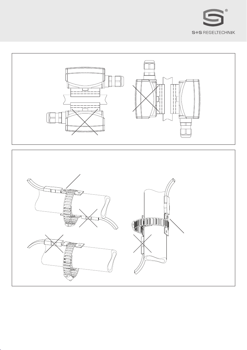
Montageschema
Mounting diagram
Schéma de montage
Схема монтажа
Montageschema
Mounting diagram
Schéma de montage
Схема монтажа
TW - extern
TW - external
TW - externe
TW - наружный
TW
Sensor
oben /außen
Sensor
on top / outside
Capteur
en haut / à l’extérieur
Датчик
сверху/ снаружи
Sensor
außen / seitlich
Sensor
outside / at the side
Capteur
à l’extérieur / sur le côté
Датчик
снаружи/ сбоку
© Copyright by S+S Regeltechnik GmbH
Nachdruck, auch auszugsweise, nur mit Genehmigung von S+S Regeltechnik GmbH gestattet.
Reprints, in part or in total, are only permitted with the approval of S+S Regeltechnik GmbH.
La reproduction des textes même partielle est uniquement autorisée après accord de la société S+S Regeltechnik GmbH.
Перепечатка, в том числе в сокращенном виде, разрешается лишь с согласия S+S Regeltechnik GmbH.
HYGRASREG® TW
D G F r
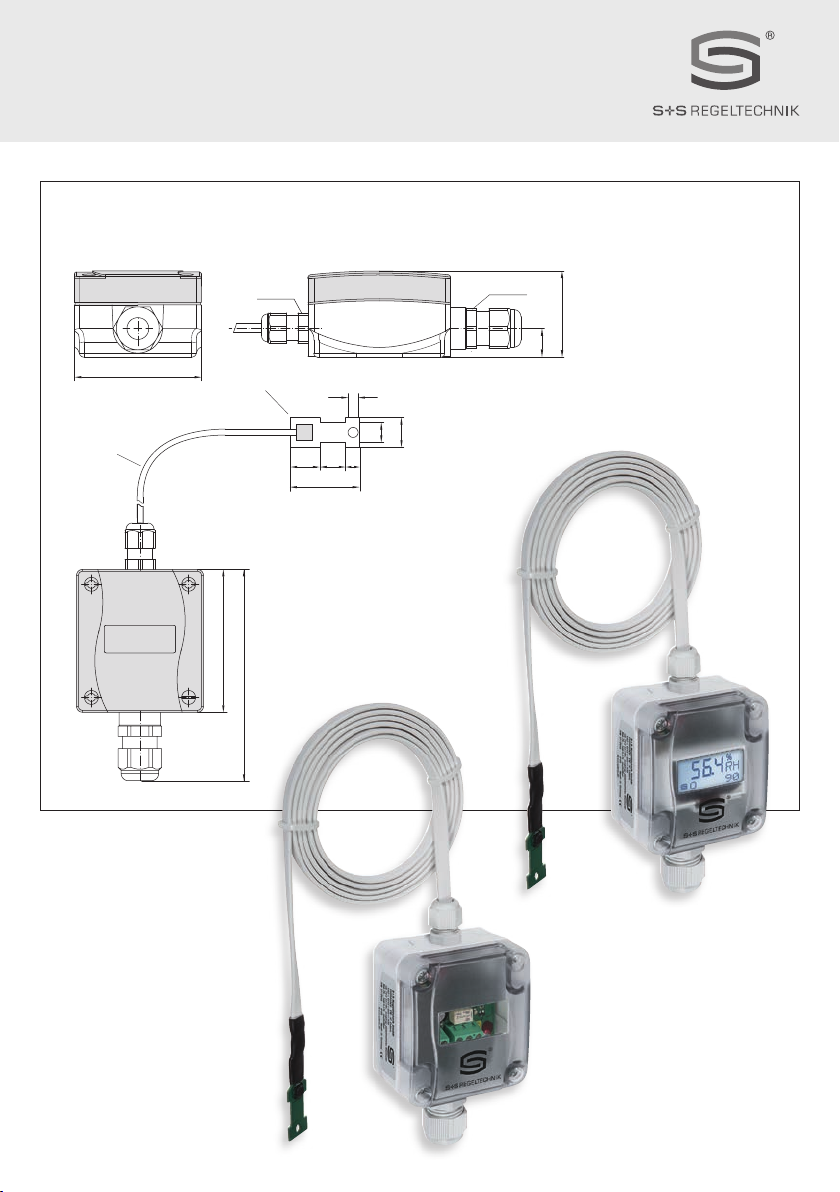
Maßzeichnung
Dimensional drawing
Plan coté
Габаритный чертеж
TW - extern
TW - external
TW - externe
TW - наружный
TW - extern
mit abgesetzten Fühlerkopf
zur Rohrmontage
TW - external
with detached sensor head
for mounting on pipes
TW - externe
avec sonde déportée
pour montage sur tube
TW - наружный
с вынесенной чувствительной
головкой монтаж на трубах
15
Sensor
~107
72
KL
35
15
10
13 7
ø
3
M12x1.5
64
14.8
43.3
M16x1.5
15
Sensor
~107
72
KL
35
15
10
13 7
ø
3
M12x1.5
64
14.8
43.3
M16x1.5
This manual suits for next models
11
Table of contents
Languages:
Popular Switch manuals by other brands

C&C TECHNIC
C&C TECHNIC Smart View IC-714-IA user manual

SMC Networks
SMC Networks TigerSwitch SMC6708L2 INT Specification sheet

Comelit
Comelit IPSWC160A manual

Moxa Technologies
Moxa Technologies SPL-24 Quick installation guide

StarTech.com
StarTech.com SV211HDUC quick start guide

Kontron
Kontron CP6930-1 user guide

Videotec
Videotec SM84A operating instructions

Hama
Hama Premium Silver USB 2.0 Hub 1:4 Operating instruction

foxunhd
foxunhd FX-SDI-401 operating instructions

Brocade Communications Systems
Brocade Communications Systems DCX-4S quick start guide

Silicon Graphics
Silicon Graphics VBOB owner's guide

HP
HP 1810-48G Quick setup guide


