Sporty's SP-400 User manual

111
AIR BAND TRANSCEIVER
SP-400
OPERATING MANUAL
(DRAFT)

FCC ID :DY7RT8059
2
Table of Contents
1. General Information ・・・・・・・・・・・・・・・・・・・・・・・・ 1
Features ・・・・・・・・・・・・・・・・・・・・・・・・・・・・・・ 1
2. Controls ・・・・・・・・・・・・・・・・・・・・・・・・・・・・・・ 2
Top View ・・・・・・・・・・・・・・・・・・・・・・・・・・・・・・ 3
Left Side View ・・・・・・・・・・・・・・・・・・・・・・・・・・・ 3
Front Side View ・・・・・・・・・・・・・・・・・・・・・・・・・・ 4
Right Side View ・・・・・・・・・・・・・・・・・・・・・・・・・・ 5
3. Method of Charging with Battery ・・・・・・・・・・・・・・・・・ 6
4. SP-400 Operating Instructions ・・・・・・・・・・・・・・・・・・ 7
(1) Frequency Selection ・・・・・・・・・・・・・・・・・・・・・・・ 7
(2) Reception of Weather Channel Broadcasts ・・・・・・・・・・・・・ 8
(3) Emergency Frequency (121.5MHz) ・・・・・・・・・・・・・・・・ 8
(4) Frequency Search (COMM) ・・・・・・・・・・・・・・・・・・・・ 8
(5) Manual Frequency Search (COMM & NAV) ・・・・・・・・・・・・・ 9
(6) Frequency Memory ・・・・・・・・・・・・・・・・・・・・・・・・ 9
(7) Memory Recall ・・・・・・・・・・・・・・・・・・・・・・・・・・ 9
(8) Memory Scan ・・・・・・・・・・・・・・・・・・・・・・・・・・ 10
(9) Memory Clear ・・・・・・・・・・・・・・・・・・・・・・・・・・ 10
(10) Transmitting ・・・・・・・・・・・・・・・・・・・・・・・・・・ 11
(11) VOR Display ・・・・・・・・・・・・・・・・・・・・・・・・・・ 11
(12) Localizer ・・・・・・・・・・・・・・・・・・・・・・・・・・ 13
(13) Localizer and Glide Path ・・・・・・・・・・・・・・・・・・・・・・ 13
(14) Key Lock ・・・・・・・・・・・・・・・・・・・・・・・・・・ 14
(15) Screen and Keypad Lighting ・・・・・・・・・・・・・・・・・・・ 14
5. Specifications ・・・・・・・・・・・・・・・・・・・・・・・・・・ 15

FCC ID :DY7RT8059
1
1. General Information
Features
SP-400 contains following function & Characteristic.
(1) Receive frequency is between 108MHz and 142.975MHz, and 10 channels of NOAA
(2) When receive frequency is between 108MHz and 117.950MHz, step-up or step-down
of the frequency will be 50kHz and it is between 118MHz and 142.975MHz, the step
will be 8.333kHz. (Equal to 25/3kHz)
(3) Transmit frequency is between 118MHz and 136.975MHz.
(4) Step-up or step-down of the frequency of the transmit frequency is 25kHz.
(5) FSS-primary-frequency is 122.1MHz.
If receive frequency was set up between 108MHz and 117.950MHz, transmit
frequency will be 122.1MHz.
(6) SP-400 contains these functions such as memory, search and scan and so on for
frequency.
(7) SP-400 possesses the Liquid Crystal Display (LCD) to indicate frequencies and
memory channels; it uses a Course Deviation Indicator (CDI) for the selected course
and is equipped with means for omni bearing selection.
(8) SP-400 indicates the selected course on the points of the compass when VOR
Navigation Signals are received.
And also indicates the Course Deviation for the selected course.
(9) SP-400 indicates the Course Deviation when a Localizer Signal and Glide slope
Signal is received.
(10) SP-400 equips the light for LCD and for keyboard.
(11) Electric power of SP-400 is supplied from battery pack of 8 "AA" size cells (R6P) or
Ni-MH Battery Pack.
(12) SP-400 acquires the FCC's license.
(13) SP-400 equips a Low Battery Indicator.
(14) Side tone for listening to your transmissions with a headset (volume controlled by
volume knob).
(15) Key lock
(16) Automatic noise limiter.

FCC ID :DY7RT8059
2
TOP
FRONT RIGHTSIDE
2. Controls
LEFTSIDE
A
B C
D E
F
G
H
I
J
L
M
N
O
P
Q
R
S
T
U
V
W
X
Y
K

FCC ID :DY7RT8059
3
Top View
(A) Antenna Connector
The flexible rubber antenna or an external antenna may be attached to this BNC connector.
(B) Earphone Jack
Using the optional Headset Adapter the earphone of a standard aviation noise-attenuating
headset may be plugged into this jack. The internal speaker is disabled when this jack is
used.
(C) Microphone Jack
Using the optional Headset Adapter the microphone of a standard aviation noise-
attenuating headset may be plugged into this jack. The internal microphone is disabled only
when this jack is used with a microphone connected to the adapter.
(D) Squelch
Rotate clockwise to increase squelch and counterclockwise to decrease squelch.
(E) On/Off and Volume Control
Combination on/off and volume control. Turn the knob clockwise from the OFF position to
turn the unit on and to increase volume. Turn the knob counterclockwise to decrease volume
and to turn the unit off.
(F) Wrist Strap Pin
The wrist strap (included as standard equipment) attaches to
this location.
Left Side View
(G) Push-To-Talk Button
This button activates the internal microphone or an external microphone when using the
optional headset adapter.
(H) Light Button
This button activates the back lighting for the screen and keypad.
(I) Battery Pack

FCC ID :DY7RT8059
4
Front View
(J) Screen
This LCD displays the current frequency, Course Deviation Indicator (CDI) and other
information to the operator.
(K) Internal Microphone
(L) Numeric Keypad
These keys are used whenever the SP-400 requires a numeric input such as setting the
frequency or Omni Bearing Selector (OBS).
(M) Emergency Frequency Key
(N) Reception of Weather Channel Broadcasts Key
This key is used to activate the Reception of Weather Channel Broadcasts mode.
(O) Clear Key
This key is used to clear erroneous key entries and to exit functions such as search, scan,
and memory storage and recall. This key is also used in combination with the Down key to
lock out all inputs to the keyboard.
(P) Omni Bearing Selector Key
This key is used to activate the Omni Bearing Selector (OBS) function for the Course
Deviation Indicator (CDI).
(Q) Memory Key
This key is used while storing frequencies in one of the 20 memory channels.
(R) Recall Key
This key is used to recall stored frequencies from the 20 memory channels.
(S) Up Key
This key is used to select the next higher frequency, select the next higher OBS setting or to
initiate search and scan functions.
(T) Down Key/Key Lock Key
This key is used to select the next lower frequency, select the next lower OBS setting or to
initiate search and scan functions. This key is also used in combination with the Clear key to
lock out all inputs to the keyboard.

FCC ID :DY7RT8059
5
(U) Memory Clear Key
This key is used to delete a selected memory channel.
(V) Internal Speaker
Right Side View
(W) Last Frequency
Lets you toggle between your last two frequencies.
(X) External Power Jack
The SP-400 may be powered externally, with or without a battery pack attached, or the
Ni-MH batteries charged by plugging the optional 12/24 Volt Cigarette Lighter Power
Adapter or the 115 Volt Wall Power Adapter into this location.
(Y) Battery Pack Release
Pushing this button releases the battery pack for removal.

FCC ID :DY7RT8059
6
3. Method of Charging with Battery
s
p
o
r
t
y
'
s
S
P
-
4
0
0
NAME FEATURE
A 120V Wall Power Adapter Charge & Adapter
B 12V / 24V Cigarette Lighter Adapter Charge & Adapter
C Desk Top Adapter Charge
INSERT
12V
9V
INPUT: 120V AC
OUTPUT: 12V DC/1000mA
INPUT:12-24V DC
OUTPUT:9V DC/1A
INPUT: 120V AC
OUTPUT: 12V DC/1000mA
SP-400 with Ni-MH Battery pack
A
12V
B
C A

FCC ID :DY7RT8059
7
4. SP-400 Operating Instructions
(1) Frequency Selection
1. If 118.000 MHz is being received and 118.700 MHz is desired.
2. Input “1” 1 is displayed and the 10 MHz column is flashing.
3. Input “1” 11 is displayed and the 1 MHz column is flashing.
4. Input “8” 118. is displayed and the 100kHz column is flashing.
5. Input “7” 118.7 is displayed and the 10kHz column is flashing.
6. Input “0” 118.70 is displayed and the 1kHz column is flashing.
7. Input “0” 118.700 is displayed.
If 4 or 9 is input in the 10kHz column, 0 is automatically selected for the 1kHz
entry and displayed.
If 2 or 7 is input in the 10kHz column, 5 is automatically selected for the 1kHz
entry and displayed.
If other number is input in the 10kHz column, the 1kHz column is flashing. And
only 0 and 5 can be inputted into a 1kHz column.
Note:
Any frequency outside of the range listed below will not be accepted. If this
happens, the unit will automatically return to its previous mode.
108.000 MHz to 117.950 MHz (50kHz step) – 200 NAV frequencies.
118.000 MHz to 142.975 MHz (8.33kHz step) – 3000 COMM frequencies.
If there is no input within five seconds during a frequency entry the unit will
automatically return to its previous mode.
If a wrong key is pressed while entering a frequency, press the CLR key and start
again.
NOTICE : CHANGES OR MODIFICATIONS NOT EXPRESSLY APPROVED BY THE
MANUFACTURER FOR COMPLIANCE COULD VOID THE USER’S AUTHORITY TO
OPERATE THE EQUIPMENT.
FCC ID :DY7RT8059
8
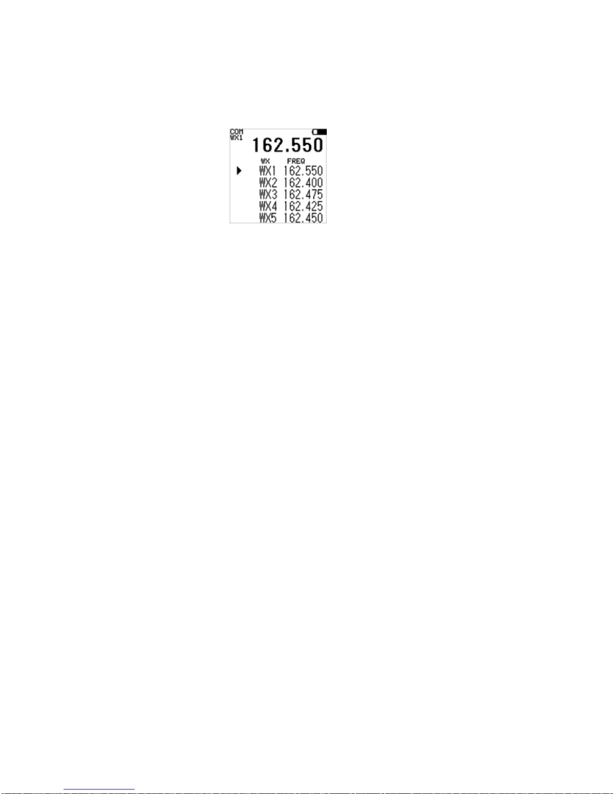
(2) Reception of Weather Channel Broadcasts
1. Press “3 WX” Weather Channels are pre-programmed at the factory.
2. Press UP or DWN to scroll through the saved channel and select the desired
frequency. (Under such a condition, Weater Channel Broadcast can be heard.)
3. Press the CLR key at any time to exit the memory recall function.
(3) Emergency Frequency (121.5MHz)
1. To access the Emergency Frequency, hold the "2 121.5" key for more than 1
second.
2. It shifts to 121.5MHz, and it comes to be able to send and receive the frequency
even in case of the state of key lock.
(4) Frequency Search (COMM)
1. If 122.700 is being received and you desire to search up or down:
2. Hold the UP or DWN key for more than 1 second and the receiver will search
through the frequencies in the selected direction. The message area of the screen
will now display SEARCH.
3. When a broadcasting signal is found the search will stop temporarily and the unit
will remain on that frequency.
4. If the signal is cut off for more than 2 seconds the receiver will return to search
mode until another signal is found.
5. During an upward or downward search the direction of the search may be
changed by pressing the appropriate key (UP or DWN) for more than 1 second.
To cancel the search mode press the key of CLR, UP or DWN.
Note:
When the upper frequency limit is reached (142.975 MHz) the search
automatically continues at the lower frequency limit (118.000 MHz).
FCC ID :DY7RT8059
9
(5) Manual Frequency Search (COMM & NAV)
1. Press the UP or DWN key to change the frequency manually by 8.33kHz
(COMM.) or 50kHz (NAV) steps.
(6) Frequency Memory
1. Enter the desired frequency either by direct selection or using the search mode.
2. Press the MEM key. The screen will display the first open memory channel (00 to
19) or 00 if all 20 channels are filled.
3. Press UP or DWN to scroll through the memory channels and select the desired
channel (00 to 19) to store the frequency. If a memory channel already has
frequency stored in it, that frequency will also be displayed with the channel
number on the memory channel list of the screen.
4. Press MEM to store the frequency in the select memory channel.
Press the CLR key at any time prior to step 4 to return to the unit to its previous
mode without saving the frequency.
Note:
If you select a channel that already contains a frequency, that frequency will be
erased when the new frequency is stored.
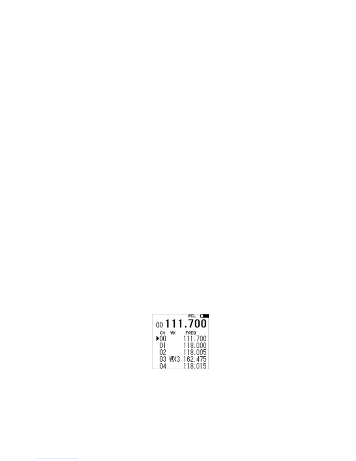
(7) Memory Recall
1. Press the RCL key. The unit will display and receive the frequency in the first
memory channel with a saved frequency.
2. Press UP or DWN to scroll through the saved channel and select the desired
frequency, or
3. Enter the desired memory channel such as 00 or 01.
Press the CLR key at any time to exit the memory recall function.
Note:
You cannot recall a vacant memory channel.
When you exit the memory recall function by pressing CLR the unit will remain
on the last frequency that was being received.

FCC ID :DY7RT8059
10
(8) Memory Scan
1. PresstheRCLkey.
2. Hold the UP or DWN key for more than 1 second and the receiver will search
through the frequencies in the selected direction. The message area of the screen
will now display SCAN.
3. When a broadcasting signal is found in one of the stored frequencies, the scan will
stop temporarily and the unit will remain on that frequency.
4. If the signal is cut off for more than 2 seconds the receiver will return to scan
mode unit another signal is found.
5. During an upward or downward scan the direction of the scan may be changed by
pressing the appropriate key (UP or DWN) for more than 1 second.
To cancel the scan mode press the key of CLR, UP or DWN.
Note:
You cannot scan vacant memory channel.
The scan mode does not work when there are no frequencies stored in memory
channels.
When you exit the memory scan function by pressing CLR the unit will remain on
the last frequency that was being received.
(9) Memory Clear
1. To clear a specific memory channel press and hold the CLR key followed by the
MEM key. Release the keys when the message area of screen displays MEM CLR.
The mode of the screen will now display MEM CLR.
2. Press the UP or DWN key to scroll through the memory channel and select the
channel to clear.
3. Press the 0 (also labeled MEM.CLR) key to clear the selected memory channel.
4. Additional memory channels may be cleared by once again pushing the UP or
DWN key to select a new channel and repeating step 3.
5. Press the CLR key to exit the memory clear function.
6. To clear all of the memory channels hold down the CLR key while using the
volume knob to turn the unit on.
Note:
You cannot clear a memory channel that does not have a frequency stored in it.
FCC ID :DY7RT8059
11
(10) Transmitting
1. If the unit is receiving a COMM frequency, 122.700 MHz for example, the screen
will display “122.700”.
2. Press the PTT key and the unit will broadcast over the selected frequency. The
screen will display “122.700” and “TX”.
3. Release the PTT key and the unit will return to receiving the selected frequency.
The screen will once again display “122.700”.
4. When any NAV frequency (108.000 MHz to 117.950 MHz) is selected the unit will
automatically broadcast on 122.100 MHz any time the PTT key is pushed.
5. When any WX channel frequency is selected the unit will automatically broadcast
on 122.100 MHz any time the PTT key is pushed.
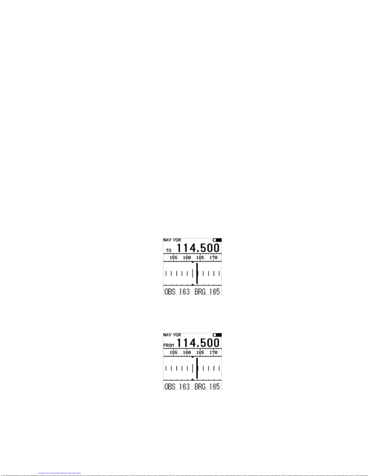
(11) VOR Display
1. Enter the desired VOR frequency, 114.500 MHz for example.
2. The unit will display the bearing to the station with the CDI needle initially
centered.
3. Press the CLR key to toggle between bearing to and radial from the station.

FCC ID :DY7RT8059
12
4. Unless otherwise changed the bearing to or radial from will not change. The CDI
needle will move to indicate the deviation from the selected bearing or radial as
the aircraft moves. Each division is a two-degree deviation beginning with the
side of the circle being two degrees. This gives the display the ability to show a
ten-degree deviation to the right or to the left.
5. To enter a desired bearing or radial press the OBS key followed by the desired
three digits. Three digits are required for every entry (30°would be entered as 0
3 0). No additional input is accepted to change the desired bearing or radial
unless the OBS key is pressed again. If all three digits are not entered within 5
seconds, the unit will automatically return to its previous mode.
6. The CDI needle will indicate the deviation from the selected bearing or radial.
7. An alternate method to enter a desire bearing or radial is to press the OBS key
followed by either the UP or DWN key. Hold this key until the desired bearing or
radial is obtained.
8. The CDI needle will indicate the deviation from the selected bearing or radial.
9. If at any time the actual bearing to or radial from the station is desired press the
OBS key and then press CLR key. The CDI needle will now be centered.
To exit the VOR mode enter a COMM or Localizer frequency.
FCC ID :DY7RT8059
13
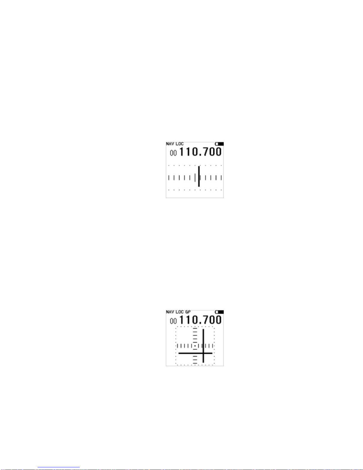
(12) Localizer
1. Enter the desired Localizer frequency, 110.700 MHz for example.
2. The CDI needle will now indicate the deviation from the localizer. Each division is
deviating of every one time that starts from the centerline. This gives the display
the ability to show a five-degree deviation to the right or to the left.
3. The display will appear as follows in the localizer mode.
To exit the localizer mode enter a COMM or VOR frequency.
(13) Localizer and Glide Path
1. The angle of approach degree to the glide slope is matched when the Glide Pass
signal is received and it is displayed in the frequency of Glide Pass that becomes
a pair as the service frequency of the localizer under the reception.
2. The display will appear as follows in the localizer and Glide Pass mode.

FCC ID :DY7RT8059
14
(13) Key Lock
1. Turning on and turning off the key Lock function change every time the CLR key
and the DWN key are pushed at the same time.
Note:
KeyLockfunctionmay be activated in all modes.
(14) Screen and Keypad Lighting
1. The screen and the keypad lighting of SP-400 work for five seconds when each key
operation and each button is operated.
2. Press and hold the LIGHT button for one second to activate and leave on the
screen and keypad lighting.
3. Press the LIGHT button a second time to turn off the screen and keypad lighting.

FCC ID :DY7RT8059
15
5. Specifications
(Specifications may change without notice due to the modifications)
General
(1) Operating Temperature Range: from -30 to +50 Degree C
(Below 0 degree C, response of LCD becomes slow.)
(2) Rated Voltage: 9.6V
(3) Operating voltage : Transmit: 7.2 to 12V
Receive: 7.2V to 12V
(4) DC power Requirement:
at Transmit: 1A(maximum)
at Receive: 70mA(Standby) TYP
at Full Volume: 380mA
(5) Antenna Input-Output Impedance: Nominal 50 ohm (unbalance)
(6) Receive-radio-Wave Form: 6K00A3E
(7) Transmit-radio-Wave Form: 6K00A3E
(8) Dimensions: 63.5mm(W) x 143.8mm(H) x 40.5mm(D)
(With the battery case, without protrusions)
Transmitter
(1) Frequency Range: 118.000MHz to 136.975MHz
(Communication CH is 760CH in 25kHz step)
(2) System: Low Power Modulation
Maximum Modulation: 85%
(3) Carrier Frequency Output: 1.5W+-20%
(4) Peak transmit power: 5W(PEP) modulation 85%
Receiver
(1)Frequency Range
: 108.000MHz to 117.950MHz (Navigation 200CH in 50kHz step)
: 118.000MHz to 142.975MHz (Communication 2998cH in 8.333kHz step)
: NOAA Weather band 10ch
: 330.950MHz to 334.700MHz
(Glide slope 40CH coupled to LOC frequency)
(2)System: Double Super Heterodyne
(a) 1st Local Oscillator: PLL System
(b) 2nd Local Oscillator: Crystal-Controlled 20.945MHz
(3)Intermediate Frequency
(a) 1st IF :21.4MHz
(b) 2nd IF :455kHz

FCC ID :DY7RT8059
16
(4) Sensitivity : 2uVolt
(Modulation Frequency at 1,000kHz and 30%)
: signal to noise ratio is 6dB and more
(5) Audio output: Maximum Output 350mW and more
(at 10% distortion)
Electrical
* Radio frequency signal voltage which is mentioned means the release voltage of
standard.(0dBu=1uV)
* All of the supply Voltages in this specification are the rated voltage 9V except any
definition.
Transmitter Section
Inspection standards
(1)Frequency Deviation: +/- 0.003%
(2)Transmitting Output: Carrier Frequency Output: 1.5W+-20%
(3)Modulation Characteristic
(a)Distortion level: Frequency 1,000Hz-AM-80%: 10% or less
(b)Modulation level
: Modulation Frequency 1,000Hz & -30dBm Input level: 70% or more
0dBm Input level: 85% to 100%
(c) Overall frequency response characteristic
: Audio output at changing frequency to 350Hz
through 2500Hz, having used standard frequency, as
1kHz is less than 6dB.
(4) Parasitic Oscillation: Should be 0
(5) Spurious Radiation: High Frequency and other -60dB or less un-desire
output level is deserves to fundamental output level
(6) Transmit-Noise : Modulation-frequency: 1000Hz,
modulation-factor:80%
Transmit-noise of frequency which
separated +/-50kHz from carrier
:higher 50dB from carrier level.
(7)Signal to Noise Ratio : Modulation-frequency
: 1000Hz, modulation-factor:80% Ratio: higher than 35dB.

FCC ID :DY7RT8059
17
Receive Section
Inspection standards
(1) Receive Sensitivity
: Set to 50mW of audio outputs at 1000Hz of modulation
frequencies, and 30% of modulation factors.
: Antenna input voltage required to obtain signal-to-noise-ratio
6dB: below 2uV
(2) Spurious Response: 50dB or more
(3) Selectivity and bandwidth
(a)6dB : ±7kHz or more
(b)60dB: ±30kHz or less
(4)Oscillation frequency drift
After power-up 10 minutes: Less than +/-0.003%
(5)Leakage signal of antenna terminal: -59dBm or less
(6)The maximum audio output
Antenna terminal input signal sets to 46dB,
1000Hz of modulation frequencies, and 85% of modulation factors.
: Audio output of 10% of distortion rates: 350mW or more.
(7)Overall frequency response characteristic
Antenna terminal input signal sets to 46dBu,
1000Hz of modulation frequencies, and 85% of modulation factors.
: within 350Hz through 2500Hz in modulation frequency. :
Less than 6dB
(8)AGC Characteristics
: The deviation of Audio output level.
Antenna terminal input signal sets to
110dBus from 20dBus, 1000Hz of
modulation frequencies, and 30% of modulation factors. :
Less than 6dB
(9)Squelch Characteristics :
(a) Minimum level: 0dBu or less
(b) Maximum level: 20dBu or less
(10) VOR course deviation: Between 2.25u to 10mV: +/-1 degree
(11) Localizer and Glide slope course deviation
: Between 2.25u to 10mV: +/-1/2 degree
Table of contents
Other Sporty's Transceiver manuals


