spotzero Mobile Pro Mini User manual


Table of Contents
Introduction � � � � � � � � � � � � � � � � � � � � � � � � � � � � � � � � � � � � � � � � � � � � � � � � � � � � � � � � � � � � � � � � � � � � � � � � � � � � � � � � � � � � 4
Safety . . . . . . . . . . . . . . . . . . . . . . . . . . . . . . . . . . . . . . . . . . . . . . . . . . . . . . . . . . . . . . . . . . . . . . . . . . . . . . . . . . . . . . . . . . . 4
Common Acronyms and Abbreviations . . . . . . . . . . . . . . . . . . . . . . . . . . . . . . . . . . . . . . . . . . . . . . . . . . . . . . . 4
Operating Specications � � � � � � � � � � � � � � � � � � � � � � � � � � � � � � � � � � � � � � � � � � � � � � � � � � � � � � � � � � � � � � � � � � � � � � � 5
Pre-Filtration . . . . . . . . . . . . . . . . . . . . . . . . . . . . . . . . . . . . . . . . . . . . . . . . . . . . . . . . . . . . . . . . . . . . . . . . . . . . . . . . . . . . 5
Pump and Motor . . . . . . . . . . . . . . . . . . . . . . . . . . . . . . . . . . . . . . . . . . . . . . . . . . . . . . . . . . . . . . . . . . . . . . . . . . . . . . . . 5
Feed Water . . . . . . . . . . . . . . . . . . . . . . . . . . . . . . . . . . . . . . . . . . . . . . . . . . . . . . . . . . . . . . . . . . . . . . . . . . . . . . . . . . . . . 5
Electrical Requirements . . . . . . . . . . . . . . . . . . . . . . . . . . . . . . . . . . . . . . . . . . . . . . . . . . . . . . . . . . . . . . . . . . . . . . . . 6
Plumbing Connections . . . . . . . . . . . . . . . . . . . . . . . . . . . . . . . . . . . . . . . . . . . . . . . . . . . . . . . . . . . . . . . . . . . . . . . . . 6
Normal Operation � � � � � � � � � � � � � � � � � � � � � � � � � � � � � � � � � � � � � � � � � � � � � � � � � � � � � � � � � � � � � � � � � � � � � � � � � � � � � � 7
Set Up . . . . . . . . . . . . . . . . . . . . . . . . . . . . . . . . . . . . . . . . . . . . . . . . . . . . . . . . . . . . . . . . . . . . . . . . . . . . . . . . . . . . . . . . . . . .7
General Use . . . . . . . . . . . . . . . . . . . . . . . . . . . . . . . . . . . . . . . . . . . . . . . . . . . . . . . . . . . . . . . . . . . . . . . . . . . . . . . . . . . . . 8
System Performance . . . . . . . . . . . . . . . . . . . . . . . . . . . . . . . . . . . . . . . . . . . . . . . . . . . . . . . . . . . . . . . . . . . . . . . . . . . 8
Filling A Vessel’s Tank . . . . . . . . . . . . . . . . . . . . . . . . . . . . . . . . . . . . . . . . . . . . . . . . . . . . . . . . . . . . . . . . . . . . . . . . . . . 8
Vessel Washing . . . . . . . . . . . . . . . . . . . . . . . . . . . . . . . . . . . . . . . . . . . . . . . . . . . . . . . . . . . . . . . . . . . . . . . . . . . . . . . . . 8
Sample System Performance . . . . . . . . . . . . . . . . . . . . . . . . . . . . . . . . . . . . . . . . . . . . . . . . . . . . . . . . . . . . . . . . . . 9
Shutdown Procedure . . . . . . . . . . . . . . . . . . . . . . . . . . . . . . . . . . . . . . . . . . . . . . . . . . . . . . . . . . . . . . . . . . . . . . . . . . .10
LCD Display Cycles . . . . . . . . . . . . . . . . . . . . . . . . . . . . . . . . . . . . . . . . . . . . . . . . . . . . . . . . . . . . . . . . . . . . . . . . . . . . . .11
PC Board and LCD Components . . . . . . . . . . . . . . . . . . . . . . . . . . . . . . . . . . . . . . . . . . . . . . . . . . . . . . . . . . . . . . . 12
LCD Maintenance Indicators . . . . . . . . . . . . . . . . . . . . . . . . . . . . . . . . . . . . . . . . . . . . . . . . . . . . . . . . . . . . . . . . . . . 12
LCD Programming and Navigation . . . . . . . . . . . . . . . . . . . . . . . . . . . . . . . . . . . . . . . . . . . . . . . . . . . . . . . . . . . . . 13
Unlocking the Keypad . . . . . . . . . . . . . . . . . . . . . . . . . . . . . . . . . . . . . . . . . . . . . . . . . . . . . . . . . . . . . . . . . . . . . . . . . .13
Resetting the Maintenance Hours . . . . . . . . . . . . . . . . . . . . . . . . . . . . . . . . . . . . . . . . . . . . . . . . . . . . . . . . . . . . . .14
Maintenance � � � � � � � � � � � � � � � � � � � � � � � � � � � � � � � � � � � � � � � � � � � � � � � � � � � � � � � � � � � � � � � � � � � � � � � � � � � � � � � � � � 15
Filter Replacement . . . . . . . . . . . . . . . . . . . . . . . . . . . . . . . . . . . . . . . . . . . . . . . . . . . . . . . . . . . . . . . . . . . . . . . . . . . . . .15
Membrane Replacement . . . . . . . . . . . . . . . . . . . . . . . . . . . . . . . . . . . . . . . . . . . . . . . . . . . . . . . . . . . . . . . . . . . . . . . 17
Preparing System for Storage or Shipment . . . . . . . . . . . . . . . . . . . . . . . . . . . . . . . . . . . . . . . . . . . . . . . . . . . 20
Recommissioning System After Storage . . . . . . . . . . . . . . . . . . . . . . . . . . . . . . . . . . . . . . . . . . . . . . . . . . . . . . 20
Winterization of the Spot Zero Mobile Pro Mini . . . . . . . . . . . . . . . . . . . . . . . . . . . . . . . . . . . . . . . . . . . . . . . . . . 21
Recommissioning System After Storage . . . . . . . . . . . . . . . . . . . . . . . . . . . . . . . . . . . . . . . . . . . . . . . . . . . . . . 22
Troubleshooting � � � � � � � � � � � � � � � � � � � � � � � � � � � � � � � � � � � � � � � � � � � � � � � � � � � � � � � � � � � � � � � � � � � � � � � � � � � � � � � 23
Temperature Correction Factors for Membrane . . . . . . . . . . . . . . . . . . . . . . . . . . . . . . . . . . . . . . . . . . . . . . 24
LCD Fault Indicators . . . . . . . . . . . . . . . . . . . . . . . . . . . . . . . . . . . . . . . . . . . . . . . . . . . . . . . . . . . . . . . . . . . . . . . . . . . 25
LCD Fault Indicators Explained . . . . . . . . . . . . . . . . . . . . . . . . . . . . . . . . . . . . . . . . . . . . . . . . . . . . . . . . . . . . . . . . 26
Bap Feed Pressure Sensor . . . . . . . . . . . . . . . . . . . . . . . . . . . . . . . . . . . . . . . . . . . . . . . . . . . . . . . . . . . . . . . . . . . . . 26
Over Current Fault . . . . . . . . . . . . . . . . . . . . . . . . . . . . . . . . . . . . . . . . . . . . . . . . . . . . . . . . . . . . . . . . . . . . . . . . . . . . . 27
Over Temperature Fault . . . . . . . . . . . . . . . . . . . . . . . . . . . . . . . . . . . . . . . . . . . . . . . . . . . . . . . . . . . . . . . . . . . . . . . 28
Over Pressure Fault . . . . . . . . . . . . . . . . . . . . . . . . . . . . . . . . . . . . . . . . . . . . . . . . . . . . . . . . . . . . . . . . . . . . . . . . . . . . 29
Low Feed Pressure Fault . . . . . . . . . . . . . . . . . . . . . . . . . . . . . . . . . . . . . . . . . . . . . . . . . . . . . . . . . . . . . . . . . . . . . . . 30
Consumable Items � � � � � � � � � � � � � � � � � � � � � � � � � � � � � � � � � � � � � � � � � � � � � � � � � � � � � � � � � � � � � � � � � � � � � � � � � � � � 31
Optional Spare Components � � � � � � � � � � � � � � � � � � � � � � � � � � � � � � � � � � � � � � � � � � � � � � � � � � � � � � � � � � � � � � � � � � � 31
Optional Dockside Pre-Filter . . . . . . . . . . . . . . . . . . . . . . . . . . . . . . . . . . . . . . . . . . . . . . . . . . . . . . . . . . . . . . . . . . . . 31
Owner’s Limited Warranty � � � � � � � � � � � � � � � � � � � � � � � � � � � � � � � � � � � � � � � � � � � � � � � � � � � � � � � � � � � � � � � � � � � � � 32

Disclaimer
The following manual was written by Spot Zero Reverse Osmosis specically for the Spot Zero Mobile
Pro Mini reverse osmosis system. The information prepared within this manual has been compiled by
Spot Zero with the best attempts to make it both comprehensive and accurate but Spot Zero makes
no denitive claim or guarantee of the completeness and accuracy of the presented information.
Spot Zero disclaims all liability for inaccuracies, omissions and outdated information.
Furthermore, any direction, recommendation, or instruction provided directly by Spot Zero Reverse
Osmosis will take precedence over the information provided within this manual.
Status at Time of Printing
Spot Zero Reverse Osmosis has always pursued continued innovation to ensure superior customer
service and produce industry leading technology. In this effort, it is possible that some of the features
and functionality discussed in this document may differ from those found within your Spot Zero
system. Therefore, it is the responsibility of the customer to take the information provided as a
reference only and to conduct due diligence to ensure proper system performance, maintenance,
and general ownership
Limitations of the Manual
To ensure proper system performance, you must use common sense and diligence when operating
your Spot Zero unit. A variety of marinas, geographical locations, and residential complexes,
have specic regulations in regards to water purication, discharge of contaminants, electrical
consumption, water consumption, and other various processes involved in reverse osmosis. It is the
responsibility of the operator to follow the ecological, biological, municipal, and other regulations
involved with the operation of the Spot Zero system. Compliance with these regulations is beyond
the scope of this manual and Spot Zero is not responsible for proper instruction in these areas.
Manufacturer’s Statements
Spot Zero Reverse Osmosis
100 SW 16th St
Fort Lauderdale, FL, 33315
Telephone: 954-533-5640
www.spotzerowater.com

Mobile Pro Mini Introduction Revision Date: 3/16/2023
4
Introduction
The Spot Zero Mobile Pro Mini is a self-contained water purication system used to remove up
to 99% of all waterborne contaminants such as heavy metals, bacteria, chlorine and many
others. Product water from the Spot Zero Mobile Pro Mini can be used to wash-down a boat,
car, RV or airplane as well as ll your vessel’s tank or ll up a glass of the purest water on Earth.
Safety
The safety section of this User Manual outlines the various safety headings used through this
manual’s text which are enhanced and dened below.
Before operating or servicing the Spot Zero Reverse Osmosis system, this User’s Manual must
be read and fully understood. Keep it and other associated information for future reference
and for new operators or personnel involved with the system.
DO NOT UNDER ANY CIRCUMSTANCES REMOVE ANY CAUTION, WARNING, OR OTHER
DESCRIPTIVE LABELS FROM THIS SYSTEM�
NOTE INDICATES STATEMENT THAT PROVIDE FURTHER INFORMATION OR CLARIFICATION
⚠ CAUTION INDICATES STATEMENTS THAT ARE USED TO IDENTIFY CONDITIONS OR
PRACTICES THAT COULD RESULT IN EQUIPMENT OR OTHER DAMAGE.
⚠ WARNING INDICATES STATEMENTS THAT ARE USED TO IDENTIFY CONDITIONS OR
PRACTICES THAT COULD RESULT IN INJURY OR LOSS OF LIFE. FAILURE TO FOLLOW
WARNINGS COULD RESULT IN SERIOUS INJURY OR EVEN DEATH.
ACRONYM DEFINITION
RO Reverse Osmosis
PSI Pounds per Square Inch
GPM Gallons Per Minute
GPD Gallons Per Day
TDS Total Dissolved Solids
PPM Parts Per Million
TCF Temperature Correction Factor
PC Board Printed Circuit Board
MGH Male Garden Hose
NPT National Pipe Thread
LED Light Emitting Diode
LCD Liquid Crystal Display
SDI Salt Density Index
Common Acronyms and Abbreviations

Mobile Pro Mini Revision Date: 3/16/2023
5
Operating Specications
Operating Specications
Your system is designed to operate with a product pressure between 10-150 psi. Ensure you
use a good quality hose capable of handling 150 psi.
Pre-Filtration
Spot Zero™ Mobile Pro Mini systems are supplied with a pre-lter (Part #: FI-FW0021) that is
used to lter out most particles over 1-micron as well as remove chlorine, chloramine, VOCs
and other heavy metals. The lter removes these waterborne contaminants through an
absorption process that consumes the life of the carbon and other activated materials within
the lter. Therefore, the pre-lter should be changed every 100 hours of use and you should
NEVER attempt to clean used lter cartridges as this may result in permanent system damage.
The pump and membranes are susceptible to damage from sediment and debris that results
from a dirty or clogged lter.
Pump and Motor
The high pressure pump used on the Spot Zero Mobile Pro Mini require a continuous and non-
turbulent ow of water to the system with a minimum feed pressure of 10-psi during operation
and not exceeding a temperature of 100°F.
⚠ CAUTION IF THE PRE-FILTER BECOMES CLOGGED OR DAMAGED AND THE WATER FLOW TO
THE PUMP IS REDUCED OR INTERRUPTED, CAVITATION WILL OCCUR. THIS CAN
LEAD TO PERMANENT PUMP DAMAGE.
Feed Water
Nothing has a greater effect on the life and performance of a reverse osmosis system than
the feed water quality. Specications for the feed water are found in the table below:
Max. Feed Temperature °F (°C) 100 (45) Min. SDI Rating < 3
Min. Feed Temperature °F (°C) 40 (4.4) Max. Free Chlorine ppm 0
Max. Ambient Temperature °F (°C) 100 (37.7) Max. TDS ppm 1,000
Min. Ambient Temperature °F (°C) 40 (4.4) Max. Hardness gpg 3
Max. Feed Pressure psi (bar) 85 (5.9) Max. pH (Continuous) 9
Min. Feed Pressure psi (bar) 10 (3.1) Min. pH (Continuous) 6
Max. Operating Pressure psi (bar) 150 (10.34) Max. Turbidity NTU 1
NOTE IT IS VERY IMPORTANT TO MEET THE MINIMUM FEED WATER REQUIREMENTS.
FAILURE TO DO SO WILL CAUSE THE MEMBRANES TO FOUL AND VOID THE
MANUFACTURER’S WARRANTY.
Mobile Pro Mini Revision Date: 3/16/2023
6
Operating Specications
Electrical Requirements
The motor used on the Spot Zero Mobile Pro Mini requires single-phase, 115-Volt, 60-Hz AC
power. Please ensure that the electrical circuit supplying the system is compatible with the
requirements of the Spot Zero Mobile Pro Mini model. A good quality extension cord, with
12-gauge wiring or better, is required providing power to the system along with a 15-Amp
breaker.
VOLTAGE AMP DRAW FREQUENCY PHASE BREAKER
115-V 10 A 60-Hertz Single 15 A
NOTE IT IS RECOMMENDED THAT A QUALIFIED ELECTRICIAN WIRES YOUR SYSTEM IN
ACCORDANCE WITH ALL APPLICABLE CODES, RULES, LAWS, AND REGULATIONS.
⚠ WARNING TO REDUCE THE RISK OF ELECTRICAL SHOCK, THE INCOMING POWER SUPPLY
MUST INCLUDE A PROTECTIVE GROUND.
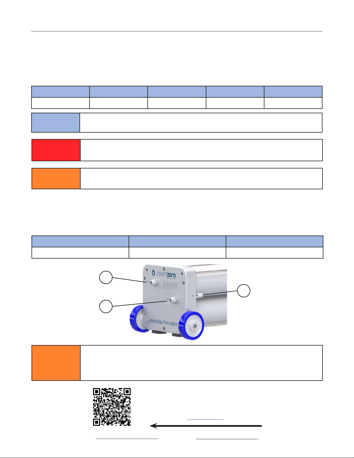
Plumbing Connections
The Spot Zero Mobile Pro Mini has 3 unique plumbing connections that must be made to
ensure proper system performance. Please see the specications and accompanying Figure
below for the external plumbing ttings sizes and locations.
1 - FEED WATER 2 - PRODUCT OUTLET 3 - DISCHARGE OUTLET
3/4” Male Garden Hose 3/4” Male Garden Hose 3/4” Hose Barb
⚠ CAUTION
ANY RESTRICTIONS OR BLOCKAGE IN THE DISCHARGE LINE CAN CAUSE
MEMBRANE SCALING AND BACK PRESSURE, WHICH WILL INCREASE THE SYSTEM’S
OPERATING PRESSURE. THIS MAY RESULT IN PERMANENT DAMAGE TO THE
SYSTEM.
1
2
3
Figure 1: Plumbing
Fitting locations
⚠ CAUTION FAILURE TO USE A PROPERLY RATED EXTENSION CORD AND/OR CIRCUIT BREAKER
CAN RESULT IN INEFFICIENT SYSTEM OPERATION OR USER INJURY OR DEATH.
For a Complete Collection of
Operating Videos and Set-Up,
Scan the QR Code or
Click HERE
Mobile Pro Mini Revision Date: 3/16/2023
7
Normal Operation
Normal Operation
Set Up
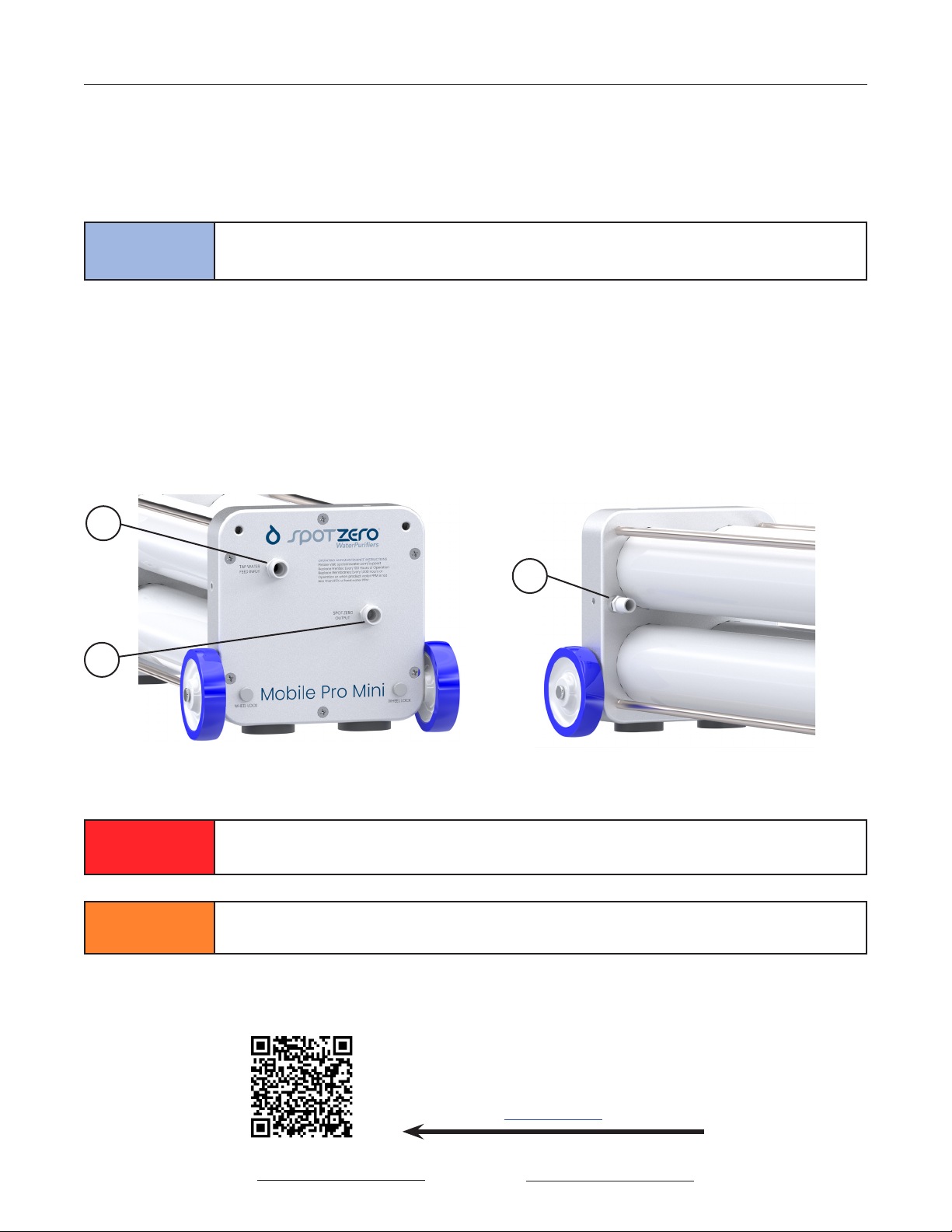
1. Attach a feed water hose to the connection port labeled TAP WATER FEED INPUT (Fig. 2, #1).
Ensure the hose used is rated with a minimum pressure rating of 150-psi to avoid bursting.
⚠ WARNING A GFCI PROTECTED OUTLET SHOULD BE USED TO SUPPLY POWER TO THIS
SYSTEM. FAILURE TO DO SO MAY RESULT IN SERIOUS INJURY OR DEATH!
⚠ CAUTION FAILURE TO OPERATE SPOT ZERO EQUIPMENT WITHIN SPECIFIED PARAMETERS
MAY RESULT IN PERMANENT DAMAGE TO SYSTEM.
Figure 2: garden Hose Plumbing connections Figure 3: Hose barb Plumbing connection
1
2
3
2. Attached a hose to the connection port labeled SPOT ZERO OUTPUT (Fig. 2, #2). Ensure the
hose used is rated with a minimum pressure rating of 150-psi to avoid bursting.
3. Ensure the discharge hose connected to the concentrate outlet hose barb (Fig. 3, #3) is
attached and free of any restriction, debris, and allows for easy water escape to an open
area.
4. Plug the attached power cord to a GFCI protected AC power receptacle.
5. Ensure the feed water conditions fall within the Feed Water Quality Specications, Pg. 5.
NOTE FOR BEST SYSTEM PERFORMANCE, UTILIZE AS SHORT OF A 3/4” HOSE AS
POSSIBLE WITH A MAXIMUM REQUIRED HOSE LENGTH OF 25-FEET.
For a Complete Collection of
Operating Videos and Set-Up,
Scan the QR Code or
Click HERE

Mobile Pro Mini Revision Date: 3/16/2023
8
Normal Operation
General Use
1. Once the LCD display is powered on, the system will be in Standby mode as indicated by
the word STANDBY intermittently displaying on the screen.
2. Once you are ready for operation, turn on the pressurized tap water feed to the system.
3. The system will begin purging air for a brief period of time.
4. Once the air is purged from the system and there is adequate feed ow, the system will
begin priming as indicated by the LCD showing PRIMING.
5. Once the system is primed and ready for performance, it will enter Ready mode as indicated
by READY displaying on the LCD.
6. The pump will turn on and the LCD will show RUNNING. The system is now ready for use.
NOTE
THERE IS A STANDBY TIMER SET FOR 10 MINUTES OF INACTIVITY. MEANING, IF THE
PRODUCT VALVE IS CLOSED FOR A PERIOD OF TIME LONGER THAN 10 MINUTES,
THE SYSTEM WILL RETURN TO STANDBY MODE INDICATED BY STEP 1 IN THE
GENERAL USE SECTION ABOVE.
System Performance
As with any uid ow application, there is a linear relationship between uid pressure and ow
rate. The same principle is applicable to the Spot Zero Mobile Pro Mini. Please see the brief
description below for best system performance based on specic application.
Filling A Vessel’s Tank
When lling a vessel’s tank, you want to achieve the greatest possible ow rate to reduce ll
time and system use. As stated in the principle above, with the greatest available ow, the
system will produce the least amount of pressure.
To achieve this type of ow, remove any nozzles or valves on the Spot Zero Output of the
Mobile Pro Mini so the ow is free from obstruction.
Vessel Washing
When spraying down a vessel with Spot Zero water, you want to achieve the greatest pressure
and ow rate to quickly and efciently wash down the vessel. As stated in the principle above,
achieving sufcient product pressure while also maintaining an ample ow rate is a balance
in the restriction of the product output from the machine.
To achieve this type of ow, most users incorporate a spray nozzle on the product output of
the system. In most applications, some restriction of the product is required to generate the
most velocity of the product water and therefore the most distance. An example of the above
application is shown on the next page.
*The tables below shows feed conditions and results for a Spot Zero Mobile Pro Mini operating
with no restrictions or nozzle on the product output� Results may vary for each customer�
PRODUCT WATER
RESULTS
GPM PPM Hose Length
2.25 GPM 19 10 Feet
FEED SOURCE
CONDITIONS
GPM Pressure Temperature PPM Hose Length
3.25 60 PSI 77° F 165 PPM 10 Feet
Mobile Pro Mini Revision Date: 3/16/2023
9
Normal Operation
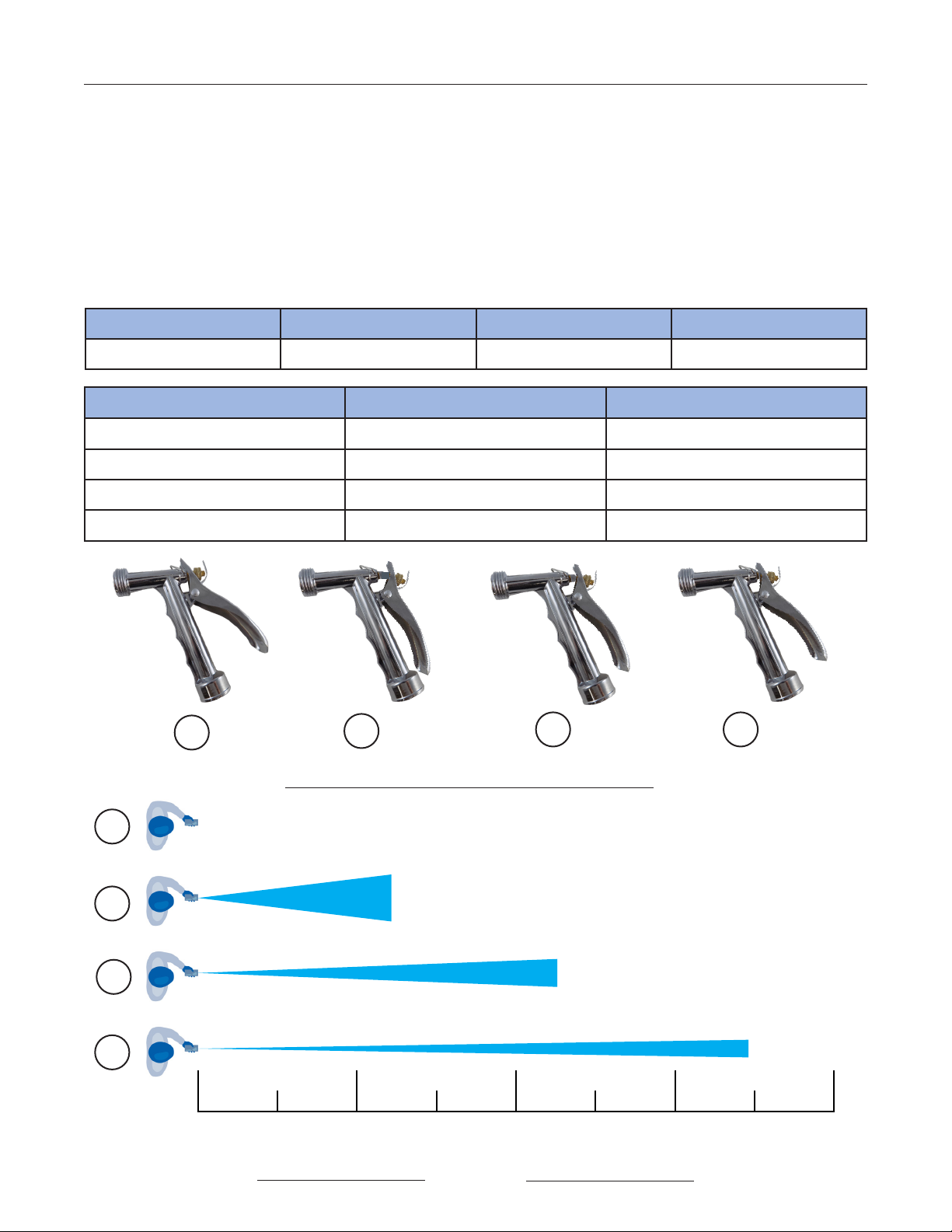
143
2
0’ 5’ 10’ 15’ 20’ 25’ 30’ 35’ 40’
4
3
2
1
Approximate Distance vs Nozzle Position
Figure Number Nozzle Position Product Flow Rate
1 CLOSED - 0% 0 GPM
2 FULLY OPEN - 100% 2.25 GPM
3 PARTIAL OPEN - ~60% 2.10 GPM
4 PARTIAL OPEN - ~40% 2.0 GPM
distance measured in Feet
Sample System Performance
System performance has been thoroughly tested and measured for the Spot Zero Mobile Pro
Mini. Performance metrics for the Mobile Pro Mini are shown below in the tables and graphics
for a washdown application where the customer is using a proportional nozzle on the product
water outlet of the system.
NOTE: The specied values for nozzle position, product ow rate, product pressure, distance,
and overall system performance were measured using new prelters, membranes and the
followingfeedwater parameters. Resultsmay varyforeachcustomerbasedon feedconditions,
temperature, lter and membrane life, pump condition and overall system condition.
Feed Source GPM Feed Source Temp� Feed Source PPM Feed Hose Length
3.25 75° F 80 PPM 10 Feet

Mobile Pro Mini Revision Date: 3/16/2023
10
Normal Operation
Shutdown Procedure
Please follow the steps below for proper shutdown of the Spot Zero Mobile Pro Mini. The system
is equipped with a built-in ushing cycle and does not require the use of a ball valve.
1. While the system is running (displaying RUNNING on the LCD), stop the flow from the SPOT
ZERO OUTPUT using an in-line valve or spray nozzle.
2. Once the product water is turned off, the system will begin auto-flushing. Allow the system
to flush uninterrupted for 3-minutes. To promote the longest membrane life, fill the vessel
with Spot Zero product water and utilize the product water and your on-board vessel
pump to feed the Mobile Pro Mini with the Spot Zero water�
3. After the flushing cycle, turn off the TAP WATER FEED INPUT. The system will shutdown
automatically.
4. Disconnect input power supply, and the TAP WATER FEED INPUT and SPOT ZERO OUTPUT
hoses.
5. Reinstall storage caps (Part Number: PF-PY0047) to SPOT ZERO OUTPUT and TAP WATER FEED
INPUT.
NOTE SYSTEM MUST BE USED OR FLUSHED EACH MONTH FOR 5-MINUTES TO PREVENT
FOULING.
NOTE IT IS NORMAL FOR THE LCD DISPLAY TO SHOW !LOW FP! FOR A SHORT PERIOD OF
TIME DURING THE SHUTDOWN CYCLE AFTER THE TAP WATER FEED SUPPLY HAS
BEEN SHUT OFF FROM THE SYSTEM.
NOTE TO PROMOTE THE LONGEST MEMBRANE LIFE, FILL THE VESSEL WITH SPOT ZERO
PRODUCT WATER AND UTILIZE THE PRODUCT WATER AND YOUR ON-BOARD
VESSEL PUMP TO FEED THE MOBILE PRO MINI WITH THE SPOT ZERO WATER.
⚠CAUTION SPOT ZERO MOBILE PRO MINI MUST BE USED/STORED IN AN ENVIRONMENT
WITH TEMPERATURES ABOVE FREEZING (32° F/0° C). DAMAGE CAUSED FROM A
FAILURE TO DO SO WILL NOT BE COVERED UNDER WARRANTY BY SPOT ZERO.
For a Complete Collection of
Operating Videos and Shutdown
Procedures, Scan the QR Code or
Click HERE

Mobile Pro Mini Revision Date: 3/16/2023
11
Normal Operation
LCD Display Cycles
The LCD will display a sequence of parameters for 1.5-seconds at a time. The display follows
the same continuous sequence unless the operating mode is changed, a fault occurs, ow is
interrupted, or the power is disengaged.
The sequence for each operating mode is shown below.
LCD DISPLAY DESCRIPTION
SpotZero Manufacturer Label
Standby Indicates Operation Sequence
FP_XXX Feed Pressure
Flt_XXX Filter Hours
Mbn_XXX Membrane Hours
Hrs_XXX Total System Hours
LCD DISPLAY DESCRIPTION
Priming Indicates Operation Sequence
FP_XXX Feed Pressure
LCD DISPLAY DESCRIPTION
Ready Indicates Operation Sequence
FP_XXX Feed Pressure
LCD DISPLAY DESCRIPTION
SpotZero Manufacturer Label
Running Indicates Operation Sequence
FP_XXX Feed Pressure
Flt_XXX Filter Hours
Mbn_XXX Membrane Hours
Hrs_XXX Total System Hours
STANDBY
RUNNING
READY
PRIMING
Mobile Pro Mini Revision Date: 3/16/2023
12
Normal Operation
LCD Maintenance Indicators
The Mobile Pro Mini is equipped with smart maintenance tracking capabilities align with
programmed reminders for system maintenance. Please see the below table for reference
on LCD maintenance indicators and corresponding required action.
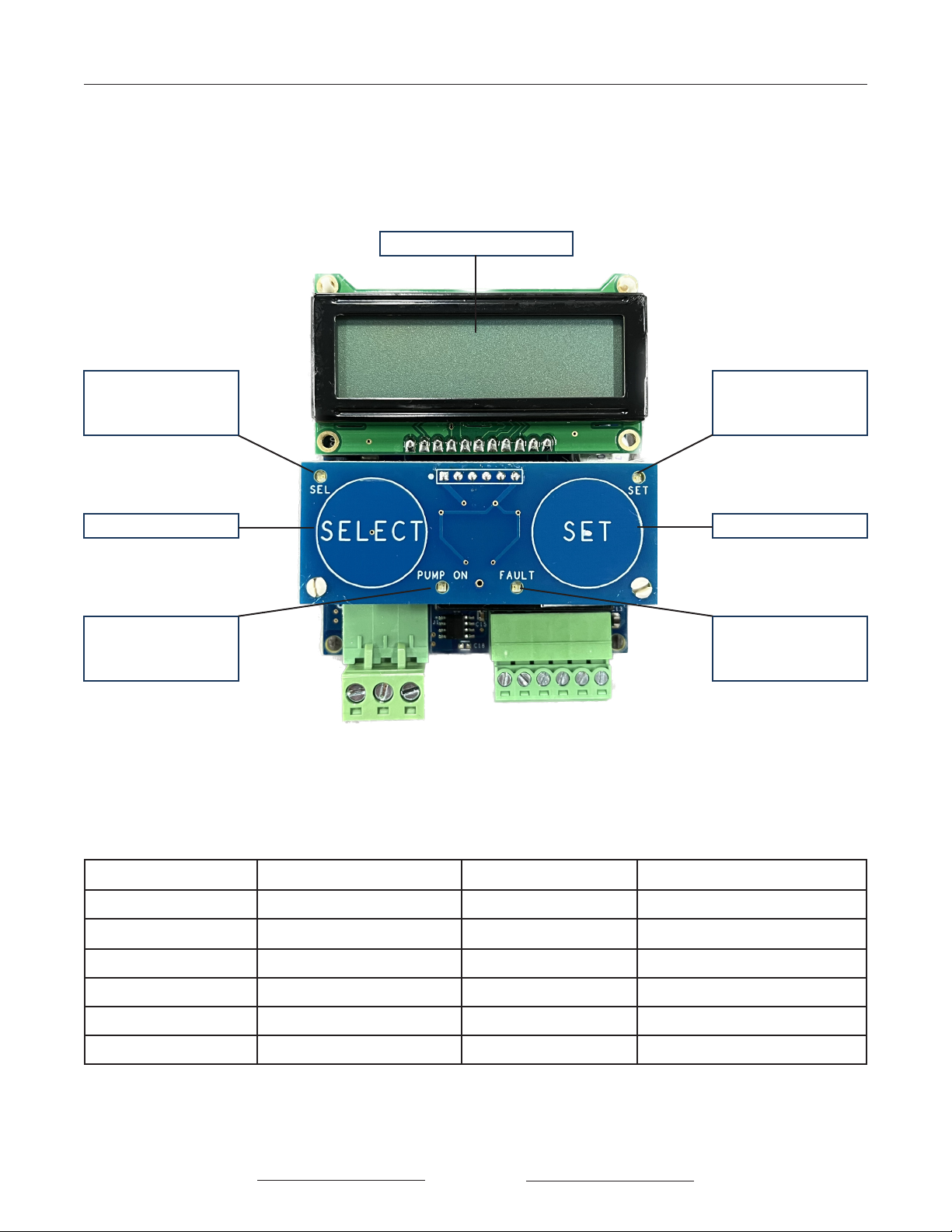
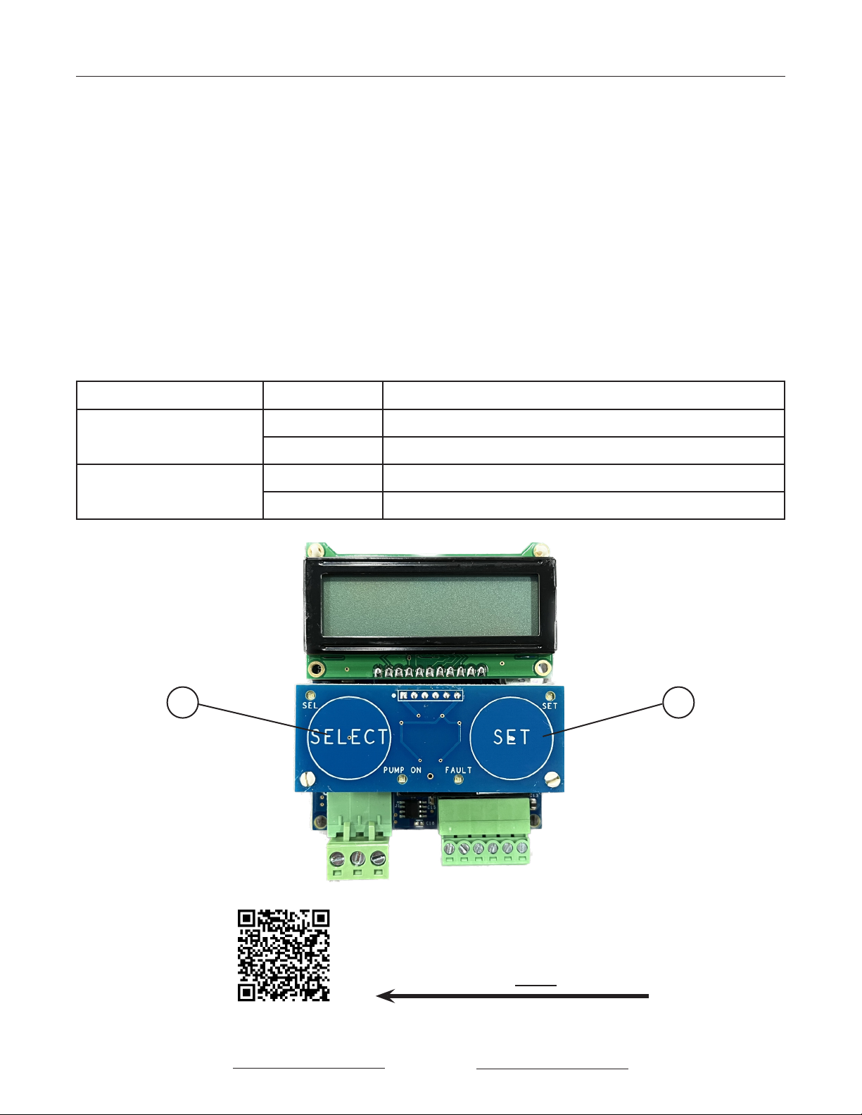
PC Board and LCD Components
The driving component behind the operation of the Spot Zero Mobile Pro Mini is the internal
PC Board and accompanying LCD Display. Indication and description of important LCD
components can be found below in Figure 4.
LED that indicates
when SELECT is
pressed
LED that indicates
when SET is
pressed
SELECT Button SET Button
LED that indicates
when the pump
is ON
LED that indicates
when the system
is in a fault state
Backlit LCD display
Figure 4: Mobile Pro Mini PC Board Reference
LCD Display LED Indicator Action Required Reference
ORDER FILTER NONE Order lter Part #: FI-FW0021
CHANGE FILTER FAULT LED slow RED ash Change lter Pg. 15
FILTER PAST DUE FAULT LED rapid RED ash Change lter Pg. 15
ORDER MEMBRANE NONE Order membrane Part Number: MM-FW0014
CHANGE MEMBRANE FAULT LED slow RED ash Change membrane Pg. 17
MEMBRANE PAST DUE FAULT LED rapid RED ash Change membrane Pg. 17

Mobile Pro Mini Revision Date: 3/16/2023
13
Normal Operation
LCD Programming and Navigation
The Spot Zero Mobile Pro Mini is preprogrammed with set recommended maintenance cycles
along with programming sequences that a customer can use to monitor system performance
more closely. Please see the below information for LCD navigation.
At any time during operation, if either the SET or SELECT buttons are pressed, the LCD will display
LOCKED for 0.5-seconds to prevent from any accidental programming or variable change.
Therefore, to reset parameters such as lter and membrane hour counters, the keypad must
be unlocked rst.
Unlocking the Keypad
Press and hold BOTH the SET (Fig. 5, #1) and SELECT (Fig. 5, #2) buttons for 3-seconds until you
see UNLOCKED display on the LCD for 0.5-seconds.
NOTE FEEDBACK TO DETERMINE IF EITHER SET OR SELECT ARE BEING PRESSED IS GIVEN
BY THE BLUE LED’S ABOVE EACH BUTTON AS SHOWN IN FIGURE 4 ON PG. 12.
12
For a Complete Collection of
Operating Videos and LCD
Navigation, Scan the QR Code or
Click HERE
Figure 5: Mobile Pro Mini PC Board Reference

Mobile Pro Mini Revision Date: 3/16/2023
14
Maintenance
Filter Replacement
Each Spot Zero Mobile Pro Mini contains one prelter that is
responsible for removing suspended solids, heavy metals,
and other contaminants before the membranes. The lter
(Part #: FI-FW0021) must be replaced every 100 hours of
operation or as needed.
The LCD display is programmed with the following indicators
to show recommended lter change intervals:
TIME LCD DISPLAY LED SEQUENCE
90 Hours ORDER FILTER None
100 Hours CHANGE FILTER Slow consistent red ash
110 Hours FILTER PAST DUE Rapid red ash
1. Ensure the water supply is turned off and hoses are disconnected from the system.
2. Ensure power is disconnected from the power supply.
3. If wheels are installed, follow the brief instructions below to remove them before continuing.
a. Unthread the Wheel Lock set screw (Part #: HW-SC0016) half-way from the plate on
the backside of the system as shown Figure 6, Item 1.
b. Slide wheel axle assembly (Part Number: MA-MP0000) out of the retaining channel
and set aside for re-installation later (Fig. 6, Item 2)
c. Repeat on opposite side.
4. Once the wheels and plumbing have been removed, unscrew the 6 end plate retaining
screws shown in Figure 6, Item 3, one at a time.
5. Hold end plate rmly with two hands and pull away from the unit to release the end plate.
2
2
1
Figure 6: WHeel assembly/removal
3
Maintenance For a Complete Collection
of Maintenance Videos
Scan the QR Code Below or
Click HERE
Mobile Pro Mini Revision Date: 3/16/2023
15
Maintenance
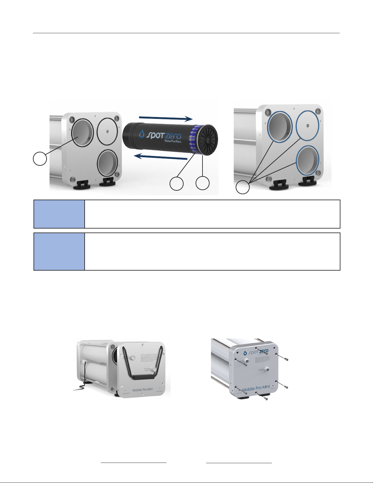
6. As shown in Figure 7, the lter is located in the top left hole through the inner end plate (#1).
7. Using either pliers or your hand, reach into the housing and rmly grasp the lter.
8. Remove the lter from the housing by pulling away from the system.
9. Install the new lter in the direction of the arrow label as shown in Figure 7, #2.
NOTE: the white seal should be the last side of the lter to enter the vessel.
10. Push the lter inside the housing until it stops.
11. Retrieve the end plate and return to the system top side up as shown in Fig. 9.
12. Align the end plate and push inward toward the system until the external edges of the
plate are ush with those of the internal end plate.
13. Return all screws to the system, properly fastening each one by hand to a torque of 50 in-lb
14. Reconnect all hoses to the system and turn on water for approximately 30-seconds to
bleed air out of the unit.
NOTE
THE NEW FILTER HAS A MEMBRANE CLEANER IN IT THAT WILL ASSIST IN CLEANING
THE MEMBRANE FILM. REMOVAL OF THESE IMPURITIES WILL ASSIST IN THE OVERALL
EFFICIENCY AND PERFORMANCE OF THE SYSTEM. DO NOT USE ANY PRODUCT
WATER UNTIL THE FOLLOWING STEPS ARE COMPLETED.
1
231
Figure 7: Filter cHange Figure 8: o-ring emPHasis
NOTE BEFORE RETURNING END PLATE TO SYSTEM FACE, ENSURE ALL O-RINGS ARE
PROPERLY INSTALLED AND HAVE NOT COME LOOSE IN THE REMOVAL PROCESS
AS SHOWN IN FIGURE 8, #1. IF NEEDED, RELUBRICATE WITH MOLYKOTE.
15. Allow the membrane cleaner solution to soak for a minimum of 30-minutes by turning
off the water supply. Longer soak times will promote greater performance. Do not let the
cleaner soak for more than 24-hours.
16. Turn the water supply on to allow the system to ush with the Spot Zero product outlet shut
for 10-minutes to remove residual cleaner. DO NOT plug in the system to power yet.
17. Reset Filter Maintenance Hours as shown on Pg. 16. Return to Normal Operation
Figure 9: end Plate re-installation Figure 10: screW re-installation
removal
installation
Mobile Pro Mini Revision Date: 3/16/2023
16
Maintenance
Resetting the Maintenance Hours
1. Unlock the keypad as explained on the previous page.
2. Press the SELECT button to see the rst programmable parameter. Continuing to press
SELECT will toggle through all parameters and will wrap around back to the beginning.
3. To begin editing a parameter, navigate to the desired parameter and press the SET button.
4. Once the parameter value is displayed, press the SET button again to change the value to
the alternate value. Each subsequent press of SET will change the value by a step.
5. To save the parameter value, press and hold both SET and SELECT buttons for 3-seconds
until the LCD displays SAVED for 1.5-seconds. Parameter setting mode will be exited and
you will be returned to the normal display sequence.
6. To exit parameter setting mode WITHOUT saving, press the SELECT button at any time, this
will return you to the parameter menu.
*The programmable parameters are shown below with all available options�
Parameter Value 1 Explanation if Saved
Flt Hrs KEEP Filter hours will remain unchanged
RESET Filter hours will reset back to 0
Memb Hrs KEEP Membrane hours will remain unchanged
RESET Membrane hours will reset back to 0
1 2
For a Complete Collection of
Operating Videos and LCD
Navigation, Scan the QR Code
Click HERE

Mobile Pro Mini Revision Date: 3/16/2023
17
Maintenance
Membrane Replacement
Each Spot Zero Mobile Pro Mini contains two RO membranes
that are responsible for the ultra-ltration of incoming
water supply. The membranes (Part #: MM-FW0014) must
be replaced every 500 hours of operation or as needed.
The LCD display is programmed with the following
indicators to show recommended membrane change
intervals:
TIME LCD DISPLAY LED SEQUENCE
490 Hours ORDER MEMBRANE Slow consistent red ash
500 Hours CHANGE MEMBRANE Slow consistent red ash
510 Hours MEMBRANE PAST DUE Solid red
1. Ensure the water supply is turned off and hoses are disconnected from the system.
2. Ensure power is disconnected from the power supply.
3. If wheels are installed, follow the brief instructions below to remove them before continuing.
a. Unthread the Wheel Lock set screw from the plate on the backside of the system as
shown in the image below.
b. Slide wheel axle assembly out of the retaining channel and set aside for re-
installation later.
c. Repeat on opposite side.
4. Once the wheels and plumbing have been removed, unscrew the 6 end plate retaining
screws shown in Figure 11 one at a time.
5. Hold end plate rmly with two hands and pull away from the unit to release the end plate.
2
2
1
Figure 11: WHeel assembly/removal
3
For a Complete Collection
of Maintenance Videos
Scan the QR Code Below or
Click HERE

Mobile Pro Mini Revision Date: 3/16/2023
18
Maintenance
6. As shown in Figure 12, the rst membrane is located in the bottom right hole through the
inner end plate (Fig. 12, #1). Using either needle nose pliers or your hand, reach into the
housing and rmly grasp the membrane by one of the black ns, ensuring not the grasp
the product tube in case inspection or reuse is required (Fig. 12).
7. Remove the membrane from the housing by pulling away from the system (Fig. 12, #2).
8. Remove the new membrane from the packaging and inspect for any nicks, cuts, or
deformities. If the white brine seal (Fig. 12, #3) is damaged, replace with a new one.
9. Lubricate the white brine seal (Fig. 12, #3) with a food grade lubricant such as Molykote.
10. Install the membrane element so the brine seal is on the side that is last to enter the
housing (Fig. 12, #3). Push the membrane into the housing until it stops, using a slight
twisting motion to ensure the brine seal stays properly seated.
11. Continue to rmly push on the membrane until it feels like it set in place.
123
Figure 12: membrane rePlacement WHeel side Figure 13: membrane o-ring emPHasis WHeel side
1
CORRECT INCORRECT
Figure 14: correct Plier use on membrane Figure 15: incorrect Plier use on membrane
NOTE BEFORE RETURNING END PLATE TO SYSTEM FACE, ENSURE ALL O-RINGS ARE
PROPERLY INSTALLED AND HAVE NOT COME LOOSE IN THE REMOVAL PROCESS
AS SHOWN IN FIGURE 13, #1. IF NEEDED, RELUBRICATE WITH MOLYKOTE.
installation
NOTE THE SIDE WITH THE WHITE SEAL
MUST BE THE LAST SIDE TO
ENTER THE HOUSING

Mobile Pro Mini Revision Date: 3/16/2023
19
Maintenance
15. Move to the opposite side of the unit and repeat Steps 5-14 to replace the second RO
membrane using Figures 18 and 19 instead of 12 and 13. The membrane is contained in the
only open hole that is visible when the second outer end plate is removed, Figure 18.
16. Reset Membrane Maintenance Hours as shown on Pg. 16. Return to Normal Operation
3211
Figure 18: membrane rePlacement lcd side Figure 19: membrane o-ring emPHasis lcd side
Figure 20: end Plate re-installation lcd side Figure 21: end Plate screW re-installation lcd side
12. Retrieve the end plate and return to the system top side up as shown in Fig. 16.
13. Align the end plate and push inward toward the system until the external edges of the plate
are ush with those of the internal end plate.
14. Return all screws to the system, properly fastening each one by hand to a torque of 50 in-lb
Figure 16: end Plate re-installation Figure 17: screW re-installation

Mobile Pro Mini Revision Date: 3/16/2023
20
Maintenance
Preparing System for Storage or Shipment
If the unit will be sitting idle for a signicant amount of time (i.e. anything longer than 1 month),
the membrane vessels must have static water replaced with membrane storage chemical
solution. The CH-03 Membrane Storage Chemical is Part #:252404263 and can be purchased
through any dealer of Spot Zero. To prepare for storage, please follow the steps below.
1. Turn the system on and ll a 5-gallon bucket with the Spot Zero product water that comes
out of the Mobile Pro Mini.
⚠ CAUTION PRODUCT WATER FROM THE MOBILE UNIT MUST BE USED FOR THE BELOW STEPS,
FAILURE TO DO SO MAY RESULT IN PERMANENT MEMBRANE DAMAGE.
2. Disconnect the inlet hose from the TAP WATER FEED INPUT tting.
3. Remove the lter from the system using Steps 1-8 shown on Pgs. 14-15.
4. Return end plate to the system and secure properly as shown in Steps 11-13 shown on Pg. 16.
5. Thoroughly mix contents on the Membrane Storage Chemical with the 5-gallons of Spot
Zero water produced in Step 1 above.
6. Run a hose from the bucket with the solution to an auxiliary pump to circulate the solution
into the unit. This pump should be hooked up into the TAP WATER FEED INPUT.
⚠ CAUTION
THE SYSTEM SHOULD NEVER BE PLUGGED IN FOR ANY OF THE ABOVE STEPS. ONLY
AN AUXILIARY PUMP SHOULD BE USED TO CIRCULATE THE SOLUTION. PLUGGING
IN THE SYSTEM AND ALLOWING THE PUMP TO RUN CAN PERMANENTLY DAMAGE
THE MEMBRANES IF ALL THE STORAGE CHEMICAL HAS NOT BEEN REMOVED FIRST.
Recommissioning System After Storage
1. Install a new pre-lter (Part #: FI-FW0021) into the system following Steps 1-17 on Pgs. 14-15.
Reconnect the TAP WATER FEED INPUT to a hose feed, as well as connect the Overboard
Discharge and SPOT ZERO OUTPUT to their respective hoses.
2. Turn on the water supply to the unit. DO NOT PLUG IN THE UNIT TO POWER YET.
3. Allow the system to ush without the pump running for approximately 30-minutes.
4. After the 30-minute ush, provide power to the unit and commence normal operation.
7. Connect a hose to the SPOT ZERO OUTPUT and run the open end to the 5-gallon bucket
from Step 1 above.
8. Connect a hose to the Overboard Discharge and run the open end to the 5-gallon bucket
from Step 1 above.
9. Turn the auxiliary pump on and circulate the solution throughout the system for a minimum
of 15-minutes. Do not drain the solution from the system.
10. Be sure to remove the hoses from the system and plug the inlets and outlets of the system
to ensure that the storage solution does not leak out of the system.
⚠ CAUTION ENSURE THE PUMP DOES NOT EXCEED 30-PSI INTO THE SYSTEM AND THE WATER
IS BELOW 110°F (44°C).
⚠ WARNING ENSURE ALL OF THE PRODUCT WATER DURING THE 30-MINUTE FLUSH IS
DISCARDED OVERBOARD. THIS IS NON-POTABLE, HIGH PPM WATER AND COULD
FOUL PLUMBING FIXTURES AND/OR DISCOLOR OR STAIN MATERIALS IT CONTACTS.
Table of contents
Other spotzero Water Filtration System manuals

Popular Water Filtration System manuals by other brands


Hydac
Hydac OLS 10-Z Series Installation and maintenance instructions

Sartorius
Sartorius Sartoclear 29XDL10-FCFFF Directions for use

Jesco
Jesco C7520 manual

Kessel
Kessel G round NS 0,25 Installation and operating instructions

novaris
novaris SFH3-800 275 Series Installation and operating instructions

GE
GE SmartWater GXUT05Z owner's manual