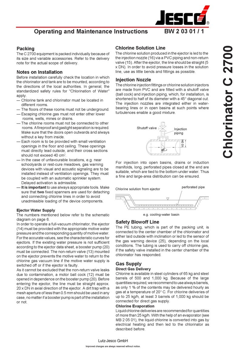
Jesco C7520 User manual

Pressure-type Chlorine Changeover Unit C 7520
BW 2 24 04 / 1
Lutz-JescoGmbH
Improvedchangesarealwaysreservedwithoutnotice.
Contents
1. Scope of supply
2. Installation
3. Wiringdiagram
4. Operation
5. Shutdown
6. Maintenance
7. Troubleshooting
1. Scope of supply
The C 7520 chlorine changeover unit is supplied
asaplate-mountedunitreadyforconnection.When
unpacking,ensure that the enclosedwall mounting
material is not lost.
2. Installation
The preassembled chlorine changeover unit is
mountedon the wall usingthescrews and washers
supplied.
Theinstallationlocationshouldbewithineasyreach
for the operating personnel so that the changeover
unitcanbeoperatedbyhandifnecessary. Itshould
not be exposed to direct sunlight or similarly bright
direct light, as this impairs the legibility of the
operatingdisplays.
2.1 Hydraulic installation
Important!
Thechlorine changeover valvesystem is designed
for use in pressure-type chlorination installations
only! The changeover unit is resistant to pure, dry
chlorine(liquid or gaseous).
Important!
Connectionsmustbecarriedoutvery carefully.Even
small leakages allow chlorine to enter the room
atmosphere and, together with air humidity, form
corrosiveair.
The automatic chlorine changeover unit may
only be operated with two connected chlorine
gas batteries. If only one chlorine gas battery
is connected, the unused side must be tightly
closed.
Check for tightness using ammonia!
Installation example

Pressure-type Chlorine Changeover Unit C 7520
BW 2 24 04 / 2
Lutz-JescoGmbH
Improvedchangesarealwaysreservedwithoutnotice.
3. Wiring diagram
2.2 Electrical installation
Beforeconnectingthepowersupply please check if
the operating voltage of the motor ball valves
correspondstolocalmainsvoltage.Thecontrol unit
itselfhasawide-rangepowerpackfor100 –240VAC
50-60Hz.
If the motor valves do not comply with the local
mains voltage they might be destroyed!
The changeover unit is operational as soon as the
power supply is connected. Only for remote
signaling of an empty cylinder/battery and the
external alarm contact another connection is
required. The terminal assignment and function of
the individual terminals can be seen in the wiring
diagram.
The external alarm contact (terminals 27 and 28)
causes both motor valves to close in the case of a
chlorine gas alarm (signaled by the chlorine gas
sensor).
Afteran interruption of thepowersupply the control
unitwillswitchautomaticallytothe side used before
in order to stick to the change rhythm and to keep
the standby battery 100% full.
Unused cable glands in the control unit must be
sealedinordertomaintainthedegreeofprotection.
Set jumper: jumper closed =
functionactivated
Forpressure operation setthejumpers as follows:
JP1Schnell: open=
nooverlapping-
motorvalvesare operated one
aftertheother
JP3Überdruck: closed=
setupfor excesspressure
operation
JP5Restentleerung:open=
periodicaloverallemptyingoff
L1
N
PE
1
100-240V/ 50-60 HzMotor 2
PE
N
Motor 1
L1(
right
)
L
1()
PE
N
L1( )
alarm
com
off
on
empty
com
off
on
GND
GND
GND
GND
2
3
4
5
6
7
8
9
10
11
12
13
14
15
16
17
18
19
20
21
22
23
24
25
26
27
28
29
30
L1( )
N
L1
PE
Slot RS 485
(Slot of programming)
JP1
JP3
JP5
JP2
15
1
Relay
Switching
power pack
right
right
right
left
left
left
gauge
Pressure
device
Gas warning
Motor 1
signal
Repeating
Motor 2
signal
Repeating

Pressure-type Chlorine Changeover Unit C 7520
BW 2 24 04 / 3
Lutz-JescoGmbH
Improvedchangesarealwaysreservedwithoutnotice.
4. Operation
As the chlorine supply battery empties, the
decreasing pressure causes the contact of the
pressuregaugeto make(withexistingliquidchlorine
phasethecontainer pressure amountsto6.8bar at
20°C and to 4.5 bar at 5°C - if the liquid phase is
used up, the container pressure drops rapidly on
further withdrawal). The corresponding LED at the
control unit changes from green to red. The
changeoverisinitiatedbytheservomotors. Whenit
iscomplete,thegreenLEDlightsupfortheoperation
of the now active chlorine supply battery. The LED
for the status of the motor valve shows green for
open,yellow duringthechangeoverprocessand red
forclosed.
Afterreplacingthe empty chlorine containersbyfull
ones, the RESET button for the corresponding
chlorinebatterymust be pressed atthecontrolunit.
The corresponding LED changes back from red to
green and indicates that this battery is again ready
for operation when required.
Manual changeover to the desired cylinder battery
is possible by pressing the corresponding key (left
or right cylinder).
Important!
Automatic changeover can only be made if the
cylinderRESETbutton is pressed after exchanging
the cylinders. If both Ready indicators are red, the
changeover unit will remain on the side connected
last until a RESET button is pressed.
Adjustment of the switch contact
The switch contact of the pressure gauge is set to
approx. 4 bar by the manufacturer. The switching
point may have to be brought into line in the plant.
The front panel of the pressure gauge must be
unscrewedforthispurpose.The switching point can
thenbeadjustedbymovingtheredmarkbetween1
and6bar.
Manual changeover (emergency operation)
The changeover valve can be operated by hand if
necessary(e.g.power failure). For thispurpose the
switch lever for manual / automatic operation at
the drive is shifted to manual. Now automatic
changeover is not possible. In any case please
switch back to automatic operation afterwards.
Slightly turn the lever until it locks.
Chlorine gas alarm
In the case of an chlorine gas alarm (only with an
alarm contact connected) both motor valves are
closedto preventfurtherchlorinegasfrom escaping.
All LEDs are flashing red. For resetting press the
RESET button. Depending on which button is
operated the changeover unit switches to the
correspondingchlorinecontainer.
5. Shutdown
Chlorinegasis hygroscopic and formshydrochloric
acid when exposed to atmospheric humidity.
Hydrochloric acid has a destructive effect on the
meteringequipment. Forthisreason,allconnections
must be sealed carefully when shutting down the
chlorination plant. All piping and valves should be
flushedwith dryair or nitrogen.
It is advisable to store the devices in a heated, dry
room if the system is to be shut down for extended
periods of time. The lines have to be tightly sealed
forthereasonsstatedabove before dismantling the
devices. When recommissioning the system,
attention must be paid in particular to any
condensation in the lines.
If necessary, this water must be expelled with dry
airor nitrogen.
6. Maintenance
ThetypeC7520 chlorine changeover unitisalmost
maintenance-free. During the annual maintenance
work,onlyavisualandfunctionaltestmustbecarried
out.Thesealsat the compression glands andinthe
ball valves must be replaced or regreased, if
necessary.
Important!
Seals may only be greased slightly with silicone
grease! Vaseline hardens in contact with chlorine
gas and will cause the ball valve to become stiff.
Particles may also be entrained by the flow of
chlorine gas and impair the correct functioning of
other valves in the system.

Pressure-type Chlorine Changeover Unit C 7520
BW 2 24 04 / 4
Lutz-JescoGmbH
Improvedchangesarealwaysreservedwithoutnotice.
7. Troubleshooting
melborpfoerutaNesuacelbissoPnoitcadednemmoceR
hctiwstonseodevlavrevoegnahC enirolhcdetcennocehthguohtlare
vo sienollufadnaytpmesiyrettab .edisrehtoehtotdetcennoc
eguagerusserptcatnoC .evitcefed erusserptcatnoceht
ecalpeR .eguag
lla(detpurretniylppusrewoP .)!kraderasDEL .ylppusrewopehtetavitcaeR
erasevlavrotomhtobroenO ."noitarepolaunam"ottes .noitarepocitamotuaotteS
.evitcefedevlavrotoM.evlavrotomecalpeR
revosehctiwstinur
evoegnahC ehthguohtlanoitarepolamrongnirud .llufllitserasreniatnocenirolhc
ehtfotniopgnihctiwsehT tessieg
uagerusserptcatnoc .yltcerrocni
ebdluohstniopgnihctiwsehT ehtwolebrab1yletamixorppa lamronroferusserpreni
atnoc .noitarepo
sisagenirolhcfowolF tonfoesuaceb.g.edetceffa ,sretimilwolf,sevlavnepoylluf .strapenilrosr
etlifytrid
wolfevomer,yllufsevlavnepO
.
senildnasretlifnaelc,sretimil
eguagerusserptcatnoC .evitcefed erusserptcatnocehtecalpeR .eguag
ehtretfaeno
nurtonodsevlavrotoM .ylsuoenatlumistubrehto gnippalrevokciuqrofrepmuJ )llenhcs(desolcsirevoegnahc
.
elbatotgnidroccarepmujteS
otyllacidoirepsehctiwslortnocehT .yrettabytpmeydaerlaeht signiyptmellarevorofr
epmuJ .desolc
.
elbatotgnidroccarepmujteS
noitisopevlavrotomfonoitacidnI lautcaehtotdnopserroctonseod .eno
gulpronoitcenn
ocelbaC .detpurretni .tcatnocekaM
.evitcefedevlavrotoM.evlavrotomecalpeR
Other manuals for C7520
1
Other Jesco Water Filtration System manuals
Popular Water Filtration System manuals by other brands
Acqua Brevetti
Acqua Brevetti PuliMATIC FT360 Installation and operating instructions

Osmosis
Osmosis MT Technical manual
Axi
Axi STS 6000 P-35 INSTRUCTION, OPERATING, & MAINTENANCE MANUAL
Midea
Midea JL1850S-RO Service manual
MARIMEX
MARIMEX ProStar Profi 4 instruction manual
Isopure Water
Isopure Water ISO-RO4 installation manual
