5
98-01504-ENUS R1
Aeros 9040 Field Computer
Multiple Sections with SDM/SFM and DCM with
ISM/ASB Setup
Multiple Sections with SDM/SFM and DCM with ISM/ASB Setup is
used when a Section Driver Module (SDM) or Switch Function Module
(SFM) is on the system along with a Dual Control Module (DCM) with
either a Input Status Module (ISM) or Automatic Switch Box (ASB).
The boom or delivery area can include up to 15 sections of varying
width and (in spreader mode) length. Additional options available with
an SDM include Application Overlap, Application Delay, and Staggered
Mode.
A Switch Function Module enables manual and automated boom
control (expandable to 20).
A Dual Control Module (DCM) connects to product implement actuators
and sensors, and controls release of the product by providing the
rate control function for the CAN Bus. Valve Control outputs can be
bidirectional or Pulse Width Modulated.
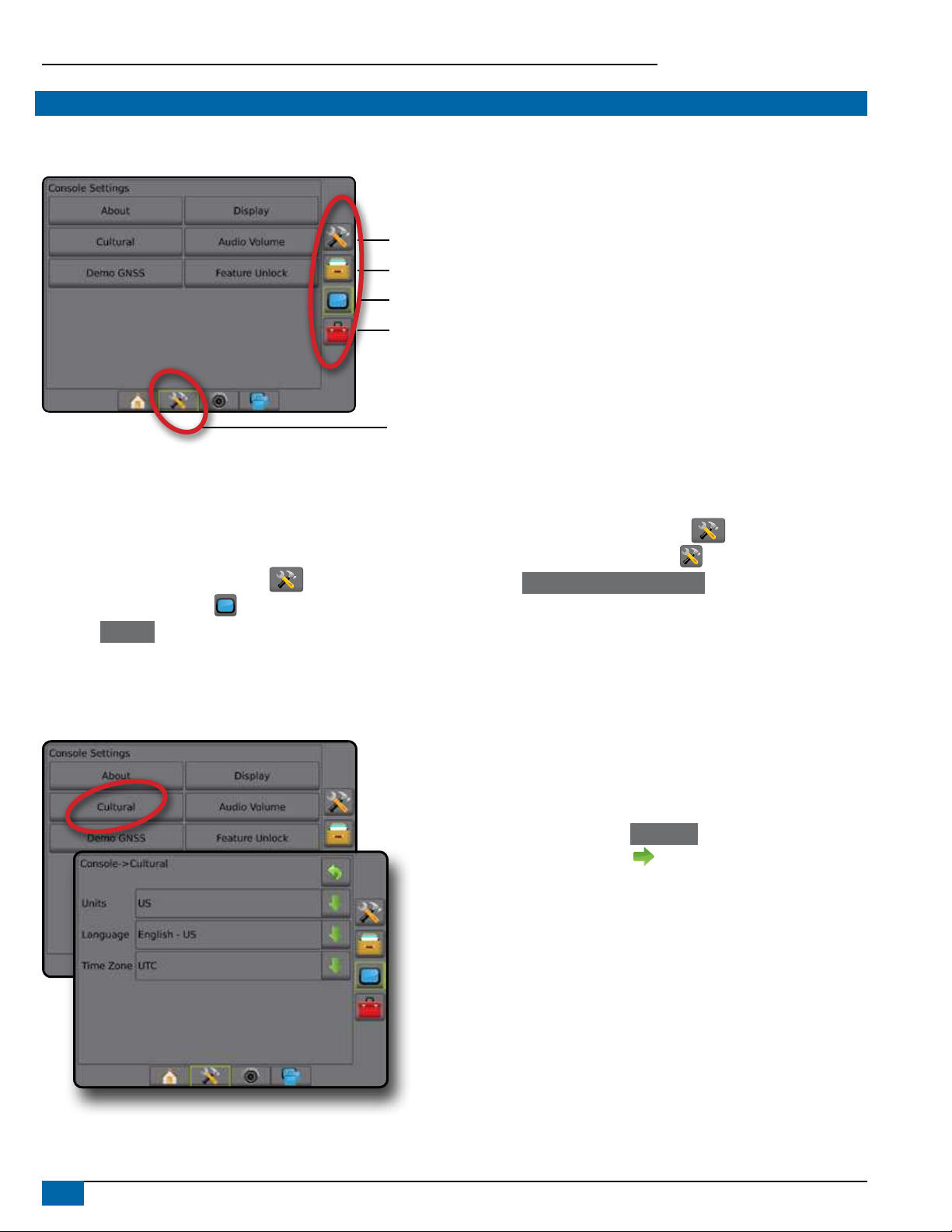
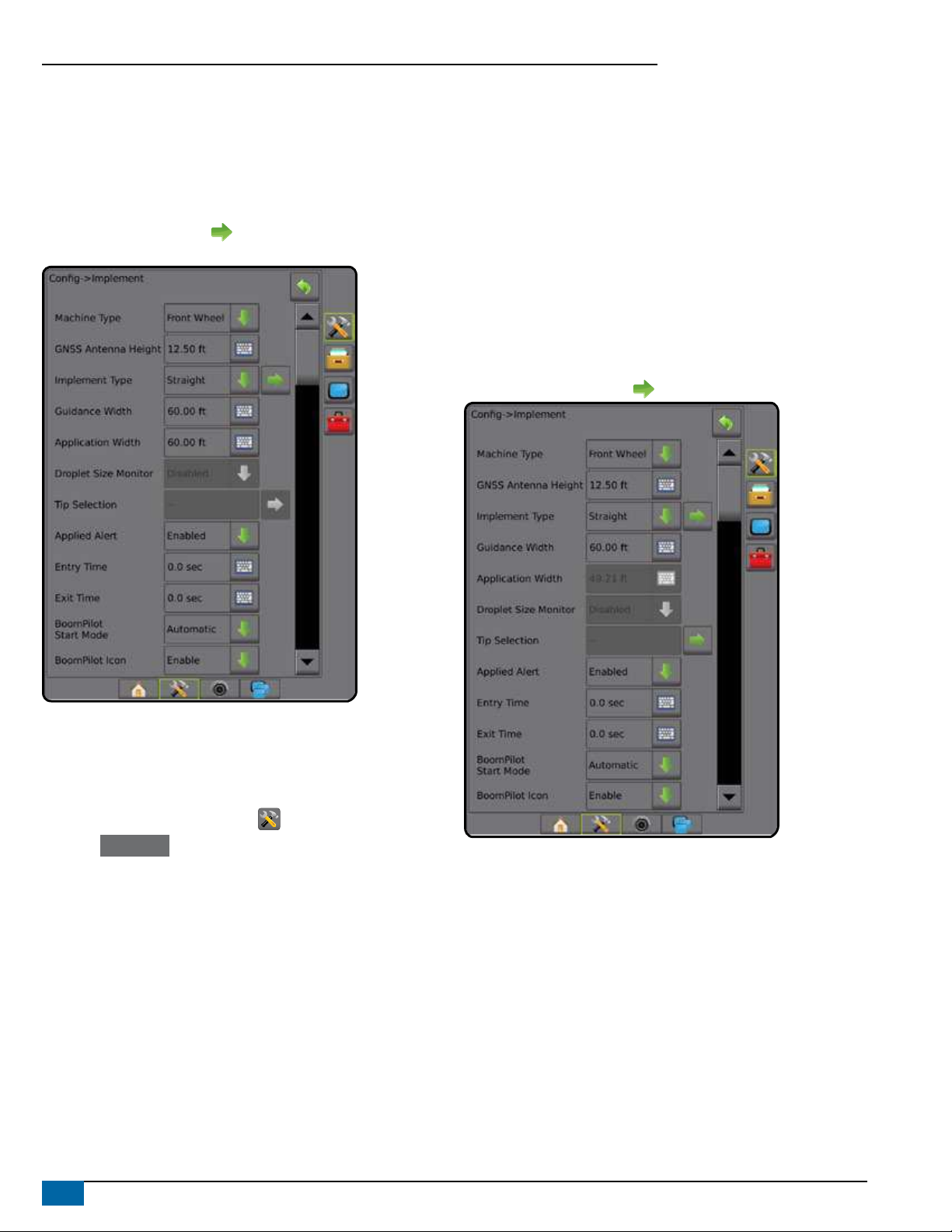
1. Press CONFIGURATION side tab .
2. Press Implement .
3. Select from:
►Machine Type [when available] – used to select the type of
machine that most closely represents your machine
►GNSS Antenna Height [when available] – used to measure the
height of the antenna from the ground
►Implement Type – used to select the layout of the sections for
the applied product location (see Implement Type section for
additional details)
►Symmetric Implement – used to establish if sections are paired
and share the same width, offset, and length values
►Multiple Section Output Modules – used to enable use of
multiple section output modules on the CAN bus
►Number of Implement Sections – used to select the number of
implement sections
►Guidance Width – used to enter the distance between the
guidelines
►Application/Working Width – enter the width of each section to
calculate the total width of all sections of the implement. Each
section can be a different width. Sections are numbered from left
to right while facing in the machine’s forward direction. Range for
each section is 0.0 to 246.06 feet / 0.0 to 75.0 meters. Total for
all sections must be greater than 3.28 feet / 1.0 meter.
NOTE: If Symmetric Implement Layout is enabled, only the
first of each pair of aligned sections will be available to be
highlighted.
►Tip Spacing – used to enter spacing between sprayer tips
►Ground Speed Override – used to set the minimum speed for
use with automatic application rate control
4. Press NEXT PAGE arrow to set up specic implement options.
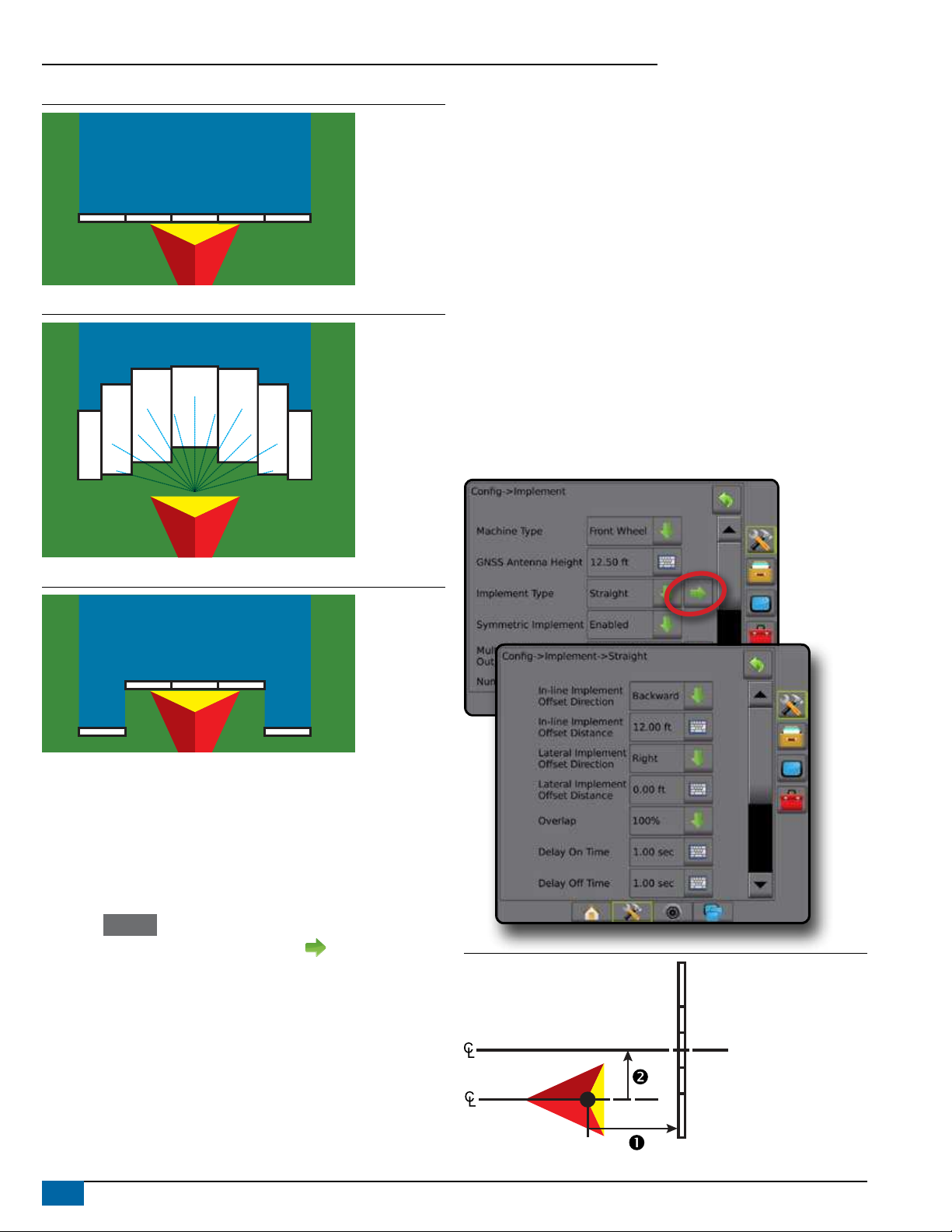
Additional Settings per Implement Type
Implement Type selects the type of application pattern that most closely
represents your system.
● In Straight Mode – the boom sections have no length and are on
a line a xed distance from the antenna
● In Spreader Mode – a virtual line is created in line with the delivery
disks from which the application section or sections can vary in
length and can be at different distances from the line (availability
depends on the specic equipment in the system)
● In Staggered Mode – a virtual line is created in line with
Section 1 from which the application section or sections have
no length and can be at different distances from the antenna
(availability depends on the specic equipment in the system)