manuals.online logo
Brands
  1. Home
  2. •
  3. Brands
  4. •
  5. Wieland
  6. •
  7. Control Unit
  8. •
  9. Wieland gesis KNX FLEX-BAS User manual

Wieland gesis KNX FLEX-BAS User manual

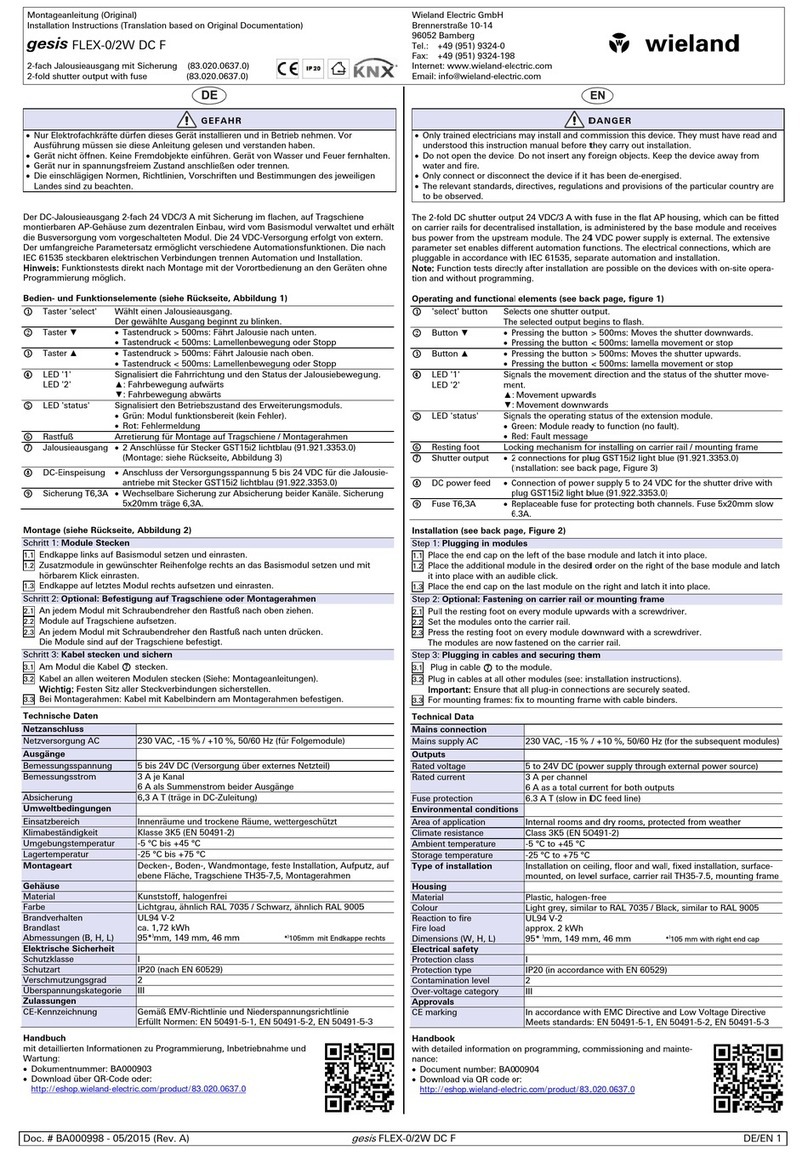
Montageanleitung (Original)
Installation Instructions (Translation based on Original Documentation)
gesis KNX FLEX-BAS
KNX-Basismodul mit AC-Einspeisung / KNX base module with AC power supply
3-phasig / 3-phase 83.020.0600.0
1-phasig (SP) / 1-phase (SP) 83.020.0601.0
Wieland Electric GmbH
Brennerstraße 10-14
96052 Bamberg
Tel.: +49 (951) 9324-0
Fax: +49 (951) 9324-198
Internet: www.wieland-
electric.com
Email: info@wieland-electric.com
Doc. # BA000896 - 08/2013 (Rev. A) gesis KNX FLEX-BAS DE/EN 1
GEFAHR
•Nur Elektrofachkräfte dürfen dieses Gerät installieren und in Betrieb nehmen. Vor
Ausführung müssen sie diese Anleitung gelesen und verstanden haben.
•Gerät nicht öffnen. Keine Fremdobjekte einführen. Gerät von Wasser und Feuer fernhalten.
•Gerät nur in spannungsfreiem Zustand anschließen oder trennen.
•Die einschlägigen Normen, Richtlinien, Vorschriften und Bestimmungen des jeweiligen
Landes sind zu beachten.
Das KNX-Basismodul im flachen, tragschienenmontierbaren AP-Gehäuse zum dezentralen
Einbau unterstützt 6 Erweiterungsmodule. Sie verfügen über alle gängigen Ein-/Ausgänge und
ermöglichen mit nur einer physikalischen Adresse eine umfassende Raumautomation. Die
Handbedienebene erlaubt Funktionstests ohne vorherige Systemintegration. Die nach IEC
61535 steckbaren, elektrischen Verbindungen trennen Automation und Installation.
Hinweis:
Funktionstests direkt nach Montage mit der Vorortbedienung an den Geräten ohne
Programmierung möglich.
Bedien- und Funktionselemente (siehe Rückseite, Abbildung 1)

Taster 'Config'
•Tastendruck > 3s: Vergibt Moduladressen und Parameter.
•Kurzer Tastendruck: Vergibt Parameter erneut.
(Voraussetzung: Moduladressen wurden bereits vergeben.)

LED 'Status'
Signalisiert den Systemstatus.
•Grün: Fehlerfreier Betrieb
•Rot: Fehlermeldung

Netzeingang
•Modul 83.020.0600.0: Stecker GST18i5
•Modul 83.020.0601.0: Stecker GST18i3
(Montage: siehe Rückseite, Abbildung 3)

Eingang KNX-Bus
Buchse BST14i2, 2-polig, grüne Codierung (Montage: Abbildung 3)

Ausgang KNX-Bus
Stecker BST14i2, 2-polig, grüne Codierung (Montage: Abbildung 3)

Taster 'KNX'
Startet den Programmiermodus für die physikalischen Adressen.
Details: siehe Handbuch

LED 'KNX''
Leuchtet im Programmiermodus rot.

Rastfuß
Arretierung für Montage auf Tragschiene/Montagerahmen
Montage (siehe Rückseite, Abbildung 2)
Schritt 1: Module Stecken
1.1 Endkappe links auf Basismodul setzen und einrasten.
1.2
Zusatzmodule in gewünschter Reihenfolge rechts an das Basismodul setzen und mit
hörbarem Klick einrasten.
1.3
Endkappe auf letztes Modul rechts aufsetzen und einrasten.
Schritt 2: Optional: Befestigung auf Tragschiene oder Montagerahmen
2.1
An jedem Modul mit Schraubendreher den Rastfuß nach oben ziehen.
2.2 Module auf Tragschiene aufsetzen.
2.3
An jedem Modul mit Schraubendreher den Rastfuß nach unten drücken.
Die Module sind auf der Tragschiene befestigt.
Schritt 3: Kabel stecken und sichern
3.1 Am Basismodul Bus- und Netzkabel stecken (Abbildung 1):
 Ausgang KNX-Bus (grün)  Eingang KNX-Bus (grün),  Netzeingang (schwarz)
3.2 Kabel an allen weiteren Modulen stecken (Siehe: Montageanleitungen).
Wichtig:
Festen Sitz aller Steckverbindungen sicherstellen.
3.3
Bei Montagerahmen: Leitungen mit Kabelbindern am Montagerahmen befestigen.
Technische Daten
Netzanschluss
Bemessungsspannung
1-phasig (83.020.0601.0)
3-phasig (83.020.0600.0)
230 VAC, -15 % / +10 %, 50/60 Hz (GST18i3)
230 V / 400 VAC, -15 % / +10 %, 50/60 Hz (GST18i5)
Bemessungsstrom
16 A je Phase
Empfohlene Absicherung
1/3-poliger Leitungsschutzschalter B16A
KNX-Busanschluss
Busspannung
24 VDC (-10 % / + 20 %)
Stromaufnahme (KNX-Bus)
Maximal 5 mA
Topologie
Twisted Pair TP1
Umweltbedingungen
Einsatzbereich
Innenräume und trockene Räume, wettergeschützt
Klimabeständigkeit
Klasse 3K5 (EN 50491-2)
Umgebungstemperatur
-5 °C bis +45 °C
Lagertemperatur
-25 °C bis +75 °C
Montageart
Decken-, Boden-, Wandmontage, feste Installation, Aufputz, auf
ebene Fläche, Tragschiene TH35-7,5, Montagerahmen
Gehäuse
Material
Kunststoff, halogenfrei
Farbe
Lichtgrau, ähnlich RAL 7035 / Schwarz, ähnlich RAL 9005
Brandverhalten
Brandlast
Abmessungen (B, H, L)
UL94 V-2
ca. 2 kWh
95*
)
mm, 149 mm, 44 mm *
)
117mm
mit Endkappe links
Elektrische Sicherheit
Schutzklasse
I
Schutzart
IP20 (nach EN 60529)
Verschmutzungsgrad
2
Überspannungskategorie
III
Zulassungen
KNX
KNX zertifiziert
CE-Kennzeichnung
Gemäß EMV-Richtlinie und Niederspannungsrichtlinie
Erfüllt Normen: EN 50491-5-1, EN 50491-5-2, EN 50491-5-3
Handbuch
mit detaillierten Informationen zu Programmierung, Inbetriebnahme und
Wartung:
•Dokumentnummer: BA000903
•Download über QR-Code oder:
http://eshop.wieland-electric.com/product/83.020.0600.0
http://eshop.wieland-electric.com/product/83.020.0601.0
DANGER
•Only trained electricians may install and commission this device. They must have read and
understood this instruction manual before they carry out installation.
•Do not open the device. Do not insert any foreign objects. Keep the device away from
water and fire.
•Only connect or disconnect the device if it has been de-energised.
•The relevant standards, directives, regulations and provisions of the particular country are
to be observed.
The KNX base module in the flat AP housing, which can be fitted on DIN rails for decentralised
installation, supports 6 extension modules. They have all the common inputs and outputs, and
they provide extensive room automation with only one physical address. The manual operation
level allows function tests without prior system integration. The electrical connections, which
are pluggable in accordance with IEC 61535, separate automation and installation.
Note:
Function tests directly after installation are possible on the devices with the manual
operation level and without programming.
Operating and functional elements (see back page, figure 1)

'Config' button
•Pressing the button > 3s: Allocates module addresses and
parameters.
•Pressing the button briefly: Allocates the parameters again.
(Precondition: The module addresses have already been allocated.)

LED for 'Status'
Signals the system status.
•Green: Fault-free operation
•
Red: Fault message

Mains input
•Module 83.020.0600.0: plug GST18i5
•Module 83.020.0601.0: plug GST18i3
(installation: see back page, figure 3)

Input for KNX bus
Socket BST14i2, 2-pole, green coding (installation: figure 3)

Output for KNX bus
Plug BST14i2, 2-pole, green coding (installation: figure 3)

'KNX' button
Starts the programming mode for the physical addresses.
Details: See handbook

LED for 'KNX'
Lights up red in programming mode.

Resting foot
Locking mechanism for installing on DIN rail/mounting frame
Installation (see back page, figure 2)
Step 1: Plugging in modules
1.1 Place the end cap on the left of the base module and latch it into place.
1.2
Place additional modules in the desired sequence on the right of the base module and
latch them into place with an audible click.
1.3
Place the end cap on the last module on the right and latch it into place.
Step 2: Optional: Fastening on DIN rail or mounting frame
2.1 Pull the resting foot on every module upwards with a screwdriver.
2.2
Place the modules on the DIN rail.
2.3
Press the resting foot on every module downwards with a screwdriver.
The modules are now fastened on the DIN rail.
Step 3: Plugging in cables and securing them
3.1 Plug in the bus cable and mains cable to the base module (figure 1):
 Output for KNX bus (green),  Input for KNX bus (green),  input Mains (black)
3.2 Plug in cables to all further modules (see installation instructions).
Important:
Ensure that all plug-in connections are securely seated.
3.3 In the case of a mounting frame: Fasten cables with cable ties to the mounting frame.
Technical data
Mains connection
Rated voltage
1-phase (83.020.0601.0)
3-phase (83.020.0600.0)
230 VAC, -15 % / +10 %, 50/60 Hz (GST18i3)
230 V / 400 VAC, -15 % / +10 %, 50/60 Hz (GST18i5)
Rated current
16 A each phase
Recommended fuse protec-
tion
1/3-phase circuit breaker B16A
Connection for KNX bus
Bus voltage
24 VDC (-10 % / + 20 %)
Current consumption (KNX
bus)
Maximum 5 mA
Topology
Twisted Pair TP1
Ambient conditions
Area of application
Internal rooms and dry rooms, protected from weather
Climate resistance
Class 3K5 (EN 50491-2)
Ambient temperature
-5 °C to +45 °C
Storage temperature
-25 °C to +75 °C
Type of installation
Installation on ceiling, floor and wall, fixed installation, surface-
mounted, on level surface, DIN rail TH35-7.5, mounting frame
Housing
Material
Plastic, halogen-free
Colour
Light grey, similar to RAL 7035 / Black, similar to RAL 9005
Reaction to fire
Fire load
Dimensions (W, H, L)
UL94 V-2
approx. 2 kWh
95*
)
mm, 149 mm, 44 mm
*) 117mm with left end cap
Electrical safety
Protection class
I
Protection type
IP20 (in accordance with EN 60529)
Contamination level
2
Overvoltage category
III
Approvals
KNX
KNX certified
CE marking
In accordance with EMC Directive and Low Voltage Directive
Meets standards: EN 50491-5-1, EN 50491-5-2, EN 50491-5-3
Handbook
with detailed information on programming, commissioning and mainte-
nance:
•Document number: BA000904
•Download via QR code or:
http://eshop.wieland-electric.com/product/83.020.0600.0
http://eshop.wieland-electric.com/product/83.020.0601.0
Montageanleitung (Original)
Installation Instructions (Translation based on Original Documentation)
gesis KNX FLEX-BAS
KNX-Basismodul mit AC-Einspeisung / KNX base module with AC power supply
3-phasig / 3-phase 83.020.0600.0
1-phasig (SP) / 1-phase (SP) 83.020.0601.0
Wieland Electric GmbH
Brennerstraße 10-14
96052 Bamberg
Tel.: +49 (951) 9324-0
Fax: +49 (951) 9324-198
Internet: www.wieland-
electric.com
Email: info@wieland-electric.com
Doc. # BA000896 - 08/2013 (Rev. A) gesis KNX FLEX-BAS DE/EN 2
Drehmoment
0,5 … 0,7 Nm
4,4 … 6,2 lb-in
Torque
Abbildung 1: Bedien- und Funktionselemente
Figure 1:
Operating and functional elements
Abbildung 2: Montage
Figure 2: Installation
Abbildung 3: Montage der Stecker
Figure 3: Installation of the plugs
Netzanschluss / Mains connection
KNX-Anschluss / KNX connection
GST18i3 (92.923.3035.1) GST18i5 (92.953.4053.1)
BST14i2 (93.422.0553.1)
Instructions de montage (Traduction de la notice originale)
Istruzioni per il montaggio (Traduzione delle istruzioni originali)
gesis KNX FLEX-BAS
Module de base KNX avec alimentation CA / Modulo base KNX con alimentazione AC
triphasé / trifase 83.020.0600.0
monophasé (SP) / monofase (SP) 83.020.0601.0
Wieland Electric GmbH
Brennerstraße 10-14
96052 Bamberg
Tel.: +49 (951) 9324-0
Fax: +49 (951) 9324-198
Internet: www.wieland-electric.com
Email: info@wieland-electric.com
Doc. # BA000896 - 08/2013 (Rev. A) gesis KNX FLEX-BAS FR/IT 1
Danger
•Seuls les électriciens spécialisés sont autorisés à installer cet appareil et à le mettre en
service. Avant de commencer, ils doivent avoir lu et compris ces instructions.
•Ne pas ouvrir l'appareil. Ne pas insérer d'objets tiers. Tenir l'appareil éloigné de l'eau et du
feu.
•Ne raccorder l'appareil ou ne le déconnecter que lorsqu'il n'est pas sous tension.
•Respecter les normes, directives, prescriptions et dispositions applicables dans chaque
pays.
Le module de base KNX dans le boîtier plat en saillie pour montage décentralisé prend en
charge 6 modules d'extension. Ils disposent de toutes les entrées/sorties et permettent une
automatisation complète de l'espace avec seulement une adresse physique. Le niveau de
commande manuelle permet d'effectuer des tests de fonctionnement sans intégration préa-
lable au système. Les raccords électriques enfichables selon CEI 61535 pour capteurs et
consommateurs séparent l'automatisation et l'installation.
Remarque :
la réalisation des tests de fonctionnement directement après le montage selon les
conditions du site sur les appareils est possible sans programmation.
Éléments de commande et de fonction (voir verso, figure 1)

Bouton 'Config'
•Appui sur le bouton > 3 s : distribue les adresses de module et les
paramètres.
•Appui court sur la touche : redistribue les paramètres.
(Condition préalable : les adresses de modules ont déjà été affectées.)

LED 'Status'
Signale l'état du système du système.
•Vert : fonctionnement sans erreur
•Rouge : message d'erreur

Entrée de réseau
•Module 83.020.0600.0 : connecteur GST18i5
•Module 83.020.0601.0 : connecteur GST18i3
(Montage : voir verso, figure 3)

Entrée du bus KNX
Prise BST14i2, bipolaire, codage vert (montage : figure 3)

Sortie du bus KNX
Connecteur BST14i2, bipolaire, codage vert (montage : figure 3)

Bouton 'KNX'
Démarre le mode de programmation pour les adresses physiques.
Détails : voir la notice

LED 'KNX'
S'allume en rouge dans le mode de programmation.

Pied encliquetable
Arrêt pour le montage sur rail porteur/cadre de montage
Montage (voir verso, figure 2)
Étape 1 : raccordement du module
1.1
Monter le capuchon d'extrémité sur le côté gauche du module de base et l'encliqueter.
1.2
Monter les modules supplémentaires dans l'ordre souhaité à droite du module de base et
les encliqueter jusqu'à entendre un clic.
1.3 Monter le capuchon d'extrémité sur le côté droit du dernier module et l'encliqueter.
Étape 2 : option de fixation sur rail porteur ou cadre de montage
2.1 Tirer le pied encliquetable vers le haut sur chaque module à l'aide d'un tournevis.
2.2 Placer les modules sur le rail porteur.
2.3
Pour le pied encliquetable vers le bas à l'aide d'un tournevis sur chaque module.
Les modules sont fixés sur le rail porteur.
Étape 3 : raccorder et sécuriser le câble
3.1 Raccorder le câble de bus et de réseau sur le module de base (figure 1) :
 Sortie du bus KNX (vert)  Entrée du bus KNX (vert),  Entrée de réseau (noir)
3.2 Raccorder le câble à tous les autres modules (voir : instructions de montage).
Important :
s'assurer de la bonne fixation de tous les raccords enfichés.
3.3 Avec cadre de montage : fixer les câbles sur le cadre de montage à l'aide de serre-câbles.
Caractéristiques techniques
Raccordement secteur
Tension nominale
monophasée (83.020.0601.0)
triphasée (83.020.0600.0)
230 VCA, -15 % / +10 %, 50/60 Hz (GST18i3)
230 V / 400 VAC, -15 % / +10 %, 50/60 Hz (GST18i5)
Intensité nominale
16 A par phase
Fusible recommandé
Disjoncteur 1/3 pôles B16A
Raccordement de bus KNX
Tension du bus
24 VCC (-10 % / + 20 %)
Courant absorbé (bus KNX)
Maximal 5 mA
Topologie
Paire torsadée TP1
Conditions ambiantes
Zones d'utilisation
Espaces intérieurs et locaux secs, protégés contre les intempéries
Résistance à l'environnement
Classe 3K5 (EN 50491-2)
Température ambiante
de -5 °C à +45 °C
Température de stockage
de -25 °C à +75 °C
Type de montage
Montage au plafond, au sol et au mur ; installation fixe, en
saillie, sur une surface plane, rail porteur TH35-7,5, cadre de
montage
Boîtier
Matériau
Matière plastique, sans halogène
Couleur
gris clair, similaire à RAL 7035 / noir, similaire à RAL 9005
Comportement au feu
Charge d'incendie
Dimensions (l, H, L)
UL94 V-2
env. 2 kWh
95*
)
mm,149 mm, 44 mm
*)117 mm avec capuchon d'extrémité
Sécurité électrique
Classe de protection
I
Indice de protection
IP20 (selon EN 60529)
Degré d'encrassement
2
Catégorie de surtension
III
Homologations
KNX
certifié KNX
Marquage CE
Conformément à la directive CEM et Basse tension
Conforme aux normes : EN 50491-5-1, EN 50491-5-2, EN 50491-5-3
Notice
comprenant des informations détaillées sur la programmation, mise en
service et maintenance :
•Numéro de document : BA000904
•Téléchargement via QR ou :
http://eshop.wieland-electric.com/product/83.020.0600.0
http://eshop.wieland-electric.com/product/83.020.0601.0
Pericolo
•L'installazione e la messa in servizio di questo apparecchio devono essere eseguiti
esclusivamente da elettrotecnici che devono aver letto e compreso le presenti istruzioni
prima di effettuare qualsiasi operazione.
•
Non aprire l'apparecchio. Non introdurre oggetti estranei. Mantenere l'apparecchio lontano
da acqua e fuoco.
•Collegare o scollegare l'apparecchio solo in assenza di tensione.
•Rispettare le norme, direttive, prescrizioni e disposizioni in vigore nel paese di impiego.
Il modulo base KNX in custodia piatta da parete su guida di supporto per installazione decen-
trata supporta 6 moduli di espansione dotati di tutti gli ingressi e le uscite necessari a permet-
tere, con un solo indirizzo fisico, un'automazione completa dell'ambiente. Il comando manuale
permette di testare le funzioni senza dover integrare il sistema. I collegamenti elettrici a
innesto con i sensori e le utenze, a norma IEC 61535, separano automazione e installazione.
Nota:
è possibile eseguire la verifica delle funzioni subito dopo l'installazione con il comando
locale presente sugli apparecchi senza alcuna programmazione.
Elementi di comando e funzionali (vedere a tergo la figura 1)

Tasto 'Config'
•Premendo il tasto per > 3s si assegnano gli indirizzi dei moduli e i
parametri.
•Premendo brevemente il tasto si riassegnano i parametri
(a condizione che gli indirizzi dei moduli siano già stati assegnati).

LED 'Stato'
Segnala lo stato del sistema.
•Verde: funzionamento senza errori
•
Rosso: segnalazione di errore

Ingresso rete
•Modulo 83.020.0600.0: connettore GST18i5
•Modulo 83.020.0601.0: connettore GST18i3
(montaggio: vedere dietro, figura 3)

Ingresso bus KNX
Presa BST14i2, 2 poli, codifica verde (montaggio: figura 3)

Uscita bus KNX
Connettore BST14i2, 2 poli, codifica verde (montaggio: figura 3)

Tasto 'KNX'
Avvia la modalità di programmazione per gli indirizzi fisici.
Per informazioni dettagliate, consultare il manuale

LED 'KNX''
Nella modalità di programmazione LED rosso.

Piedino di fissaggio
Dispositivo di fissaggio per l'installazione su guida di suppor-
to/telaio di montaggio
Montaggio (vedere a tergo, figura 2)
Passo 1: inserimento dei moduli
1.1 Inserire il cappuccio terminale a sinistra sul modulo base.
1.2
Inserire gli altri moduli nella sequenza desiderata a destra del modulo base, fino ad
avvertire il "clic" che indica l'avvenuto bloccaggio.
1.3
Applicare il cappuccio terminale sull'ultimo modulo a destra.
Passo 2: opzionale: fissaggio su guida di supporto o telaio di montaggio
2.1
Su ogni modulo spostare il piedino di fissaggio verso l'alto con un cacciavite.
2.2 Posizionare i moduli sulla guida di supporto.
2.3
Su ogni modulo premere il piedino di fissaggio verso il basso con un cacciavite.
I moduli sono ora fissati alla guida di supporto.
Punto 3: inserimento e fissaggio dei cavi
3.1 Inserire il cavo di rete e bus sul modulo di base (figura 1):
 Uscita bus KNX (verde)  Ingresso bus KNX (verde),  Ingresso di rete (nero)
3.2 Inserire i cavi in tutti gli altri moduli (vedere le istruzioni di montaggio).
Importante:
assicurarsi che tutti i connettori siano saldamente fissati.
3.3
In caso di montaggio su telaio: fissare i cavi al telaio con fascette fermacavi.
Dati tecnici
Collegamento di rete
Tensione nominale
monofase (83.020.0601.0)
trifase (83.020.0600.0)
230 VAC, -15 % / +10 %, 50/60 Hz (GST18i3)
230 V / 400 VAC, -15 % / +10 %, 50/60 Hz (GST18i5)
Corrente nominale
16 A per fase
Protezione consigliata
Interruttore magnetotermico 1/3 fase B16A
Connessione bus KNX
Tensione bus
24 VDC (-10 % / + 20 %)
Corrente assorbita (bus KNX)
Max. 5 mA
Topologia
Twisted Pair TP1
Condizioni ambientali
Campo d'impiego
In ambienti interni, asciutti e protetti dagli agenti atmosferici
Resistenza ai fattori climatici
Classe 3K5 (EN 50491-2)
Temperatura ambiente
-5 °C ... +45 °C
Temperatura di stoccaggio
-25 °C ... +75 °C
Tipo di montaggio
A soffitto, pavimento, parete, installazione fissa, a vista, su
superficie piana, guida di supporto TH35-7,5, telaio di mon-
taggio
Custodia
Materiale
PVC, senza alogenati
Colore
Grigio chiaro, simile a RAL 7035 / Nero, simile a RAL 9005
Resistenza al fuoco
Carico comburente
Dimensioni (LxHxL)
UL94 V-2
ca. 2 kWh
95*
)
mm, 149 mm, 44 mm *
)
117 mm
con cappuccio terminale
Sicurezza elettrica
Classe di protezione
I
Grado di protezione
IP20 (secondo EN 60529)
Grado d'inquinamento
2
Categoria di sovratensione
III
Omologazioni
KNX
Certificazione KNX
Marchio CE
Secondo la Direttiva EMC e la Direttiva bassa tensione
Conforme alle norme: EN 50491-5-1, EN 50491-5-2, EN 50491-5-3
Manuale
con informazioni dettagliate sulla programmazione, messa in servizio e
manutenzione:
•Documento numero: BA000904
•Download mediante codice QR o:
http://eshop.wieland-electric.com/product/83.020.0600.0
http://eshop.wieland-electric.com/product/83.020.0601.0
Instructions de montage (Traduction de la notice originale)
Istruzioni per il montaggio (Traduzione delle istruzioni originali)
gesis KNX FLEX-BAS
Module de base KNX avec alimentation CA / Modulo base KNX con alimentazione AC
triphasé / trifase 83.020.0600.0
monophasé (SP) / monofase (SP) 83.020.0601.0
Wieland Electric GmbH
Brennerstraße 10-14
96052 Bamberg
Tel.: +49 (951) 9324-0
Fax: +49 (951) 9324-198
Internet: www.wieland-electric.com
Email: info@wieland-electric.com
Doc. # BA000896 - 08/2013 (Rev. A) gesis KNX FLEX-BAS FR/IT 2
Couple
0,5 … 0,7 Nm
4,4 …
6,2 lb-in
Coppia di
serraggio
Figure 1: Éléments de commande et de fonction
Figura 1:
Elementi di comando e funzionali
Figure 2: Montage
Figura 2: Montaggio
Figure 3: Montage des connecteurs
Figura 3: Montaggio dei connettori
Raccordement secteur / Collegamento di rete
Raccordement KNX / Collegamento KNX
GST18i3 (92.923.3035.1) GST18i5 (92.953.4053.1)
BST14i2 (93.422.0553.1)

This manual suits for next models

2

Other Wieland Control Unit manuals

Wieland ricos User manual

Wieland

Wieland ricos User manual

Wieland ricos FLEX User manual

Wieland

Wieland ricos FLEX User manual

Wieland podis FCS 6 5 SI SA User manual

Wieland

Wieland podis FCS 6 5 SI SA User manual

Wieland gesis RM Series User manual

Wieland

Wieland gesis RM Series User manual

Wieland gesis FLEX-8/0 (12) User manual

Wieland

Wieland gesis FLEX-8/0 (12) User manual

Wieland gesis FLEX-MS User manual

Wieland

Wieland gesis FLEX-MS User manual

Wieland PROFIBUS-DP Series User manual

Wieland

Wieland PROFIBUS-DP Series User manual

Wieland GESIS FLEX-0/4 User manual

Wieland

Wieland GESIS FLEX-0/4 User manual

Wieland GESIS FLEX-0/2W DC User manual

Wieland

Wieland GESIS FLEX-0/2W DC User manual

Wieland SP-COP1 User manual

Wieland

Wieland SP-COP1 User manual

Wieland SA-BM-S1-4EKL-A User manual

Wieland

Wieland SA-BM-S1-4EKL-A User manual

Wieland gesis FLEX-0/2W DC F User manual

Wieland

Wieland gesis FLEX-0/2W DC F User manual

Wieland podis FCS 16 5 SI SA User manual

Wieland

Wieland podis FCS 16 5 SI SA User manual

Popular Control Unit manuals by other brands

Ebyte E220-400M22S user manual

Ebyte

Ebyte E220-400M22S user manual

DMP Electronics 714N-POE Installation and programming guide

DMP Electronics

DMP Electronics 714N-POE Installation and programming guide

Velleman PMTEMP2 manual

Velleman

Velleman PMTEMP2 manual

Rievtech x-Messenger Series user manual

Rievtech

Rievtech x-Messenger Series user manual

MOGAS ISOLATOR 2.0 Installation, operation and maintenance manual

MOGAS

MOGAS ISOLATOR 2.0 Installation, operation and maintenance manual

Qcom LR802UKN3 user manual

Qcom

Qcom LR802UKN3 user manual

DEMA 440 installation instructions

DEMA

DEMA 440 installation instructions

Cailabs CANUNDA-PULSE installation manual

Cailabs

Cailabs CANUNDA-PULSE installation manual

Watts LF919 manual

Watts

Watts LF919 manual

Crane Class 150 Operation and maintenance manual

Crane

Crane Class 150 Operation and maintenance manual

Motion MOKWCO5103-S01 user manual

Motion

Motion MOKWCO5103-S01 user manual

Supermicro SuperBlade SBI-6419P-C3N user manual

Supermicro

Supermicro SuperBlade SBI-6419P-C3N user manual

VISTEON R013-CMFB WDAB User quick reference guide

VISTEON

VISTEON R013-CMFB WDAB User quick reference guide

Garmin IMWW quick guide

Garmin

Garmin IMWW quick guide

CALEFFI 521201 NTR Installation and commissioning manual

CALEFFI

CALEFFI 521201 NTR Installation and commissioning manual

Panduit PVQ-PM installation instructions

Panduit

Panduit PVQ-PM installation instructions

Moxa Technologies WE-2100T Series user manual

Moxa Technologies

Moxa Technologies WE-2100T Series user manual

Sharp JW Series Connection manual

Sharp

Sharp JW Series Connection manual

manuals.online logo
manuals.online logoBrands
  • About & Mission
  • Contact us
  • Privacy Policy
  • Terms and Conditions

Copyright 2025 Manuals.Online. All Rights Reserved.