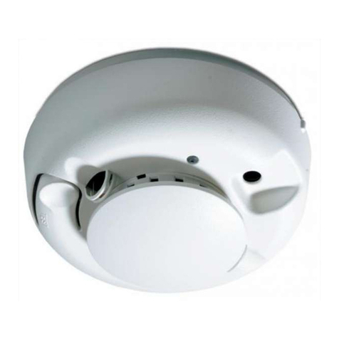
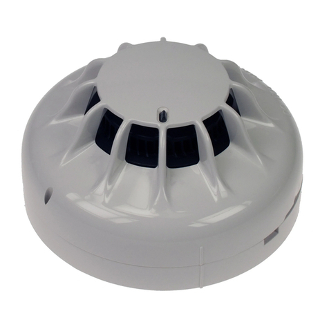
SpreadNet SN980-SMOKE User manual

1
12"
(30cm)
Max.
Never mount
in this area
Acceptable here
Top of detector
acceptable here
4"
(10cm)
4"
(10cm)
Figure 1
Mounting location
considerations
SpreadNet®
Model SN980-SMOKE
RF Photoelectric Smoke Detector
Installation Instructions
The SN980-SMOKE is a
system type smoke detec-
tor, designed for open area
protection. The unit com-
bines a Spread Spectrum
wireless transmitter with a
photoelectric smoke detec-
tor.
Spread Spectrum technol-
ogy provides higher power,
lower noise, less interfer-
ence, and longer range
than single frequency transmitters. The RF transmitter is fully su-
pervised, ensuring reliable communications.
WHERE NOT TO PLACE THE DETECTOR
When selecting a mounting location, avoid areas containing large
metal surfaces, which could affect the RF transmitter. Always test
the transmitter prior to permanently mounting it to verify signal
reception.
Avoid placing the SN980-SMOKE in areas where smoke or steam
may affect operation, such as kitchens, bathrooms, near wood
stoves or furnaces. Also avoid areas such as garages, attics, and
areas where ambient temperature may exceed 100° F (37.8° C).
• Spread spectrum technology
• Up to 100 mW transmitter
power
• EEPROM memory
• Lithium batteries included
(1 yr. expected life)
• Simple installation
• Low standby current, 40µA
• Magnetic detector functional
operation check
• Vandal resistant security
locking feature
• Highly stable operation
• RF/Transient protected
FEATURES
DETECTOR PLACEMENT
The SN980-SMOKE Photoelectric Smoke Detector is designed
to be either ceiling or wall mounted. When ceiling mounting the
SN980-SMOKE, be sure to mount the detector near the center of
the room, if possible. Do not place the detector less than 4" (10
cm) from the nearest wall. If wall mounting, do not mount within 4"
(10 cm) of the ceiling. (See Figure 1.)
Detector placement
should be established
byqualified personnel,
such as a Fire Alarm
Technician certified by
the National Institute
for Certification in En-
gineering Technolo-
gies (NICET), or a
Licensed Fire Protec-
tionEngineer. Location
and spacing of detec-
tors depends upon
such factors as ceiling
height, area to be cov-
ered, air flow conditions, and other conditions which may affect
response time. Additional information regarding detector place-
ment may be found in the National Electrical Manufacturers As-
sociation (NEMA)
Guide for the Proper Use of System Smoke
Detectors
as well as NFPA 72.
MOUNTING
The SN980-SMOKE will mount directly to the wall or ceiling.
Do NOT mount on any type gang box.
The SN980-SMOKE must be programmed prior to permanent
mounting. Refer to the PROGRAMMING THE TRANSMITTER
section below.
To mount the SN980-SMOKE, remove the detector head from
the base by turning the head counterclockwise. Mount the de-
tector base using #6 - #8 (M 3.5 - M 4) mounting screws. (See
Figure 2 below.)
Mounting Holes
Batteries (2 required)
Figure 2
SN980-SMOKE assembly,
top view (head removed)
Detector Head
Locking Screw
(Align with Alignment
Mark on Base.)
Detector Head
Alignment Mark Battery Tab
(Remove
prior to use)
To replace the head assembly, align the tamper Locking Screw
on the detector head with the Detector Head Alignment Mark
on the base. (See Figure 2 above.)
The SN980-SMOKE comes equipped with a vandal resistant
locking feature. The Locking Screw is a 1.5mm Allen head (hex-
agonal) set screw. After installing the detector head, tighten
the Locking Screw until snug.
PROGRAMMING THE TRANSMITTER
In order to program the SN980-SMOKE, the batteries must be
activated and the detector head must be in place. The follow-
ing procedure outlines the steps for programming the detector:
1 - Separate the detector head from the base as described in
the MOUNTING section.
2 - Remove the Battery Tab (see Figure 2 for Tab location).
3 - Replace the detector head, as described above. This will
enable the transmitter circuitry.
IMPORTANT: There is no power to the transmitter with the
detector head removed.

2
PROGRAMMING THE TRANSMITTER(continued)
4 - Remove the back cover (dust cover) from the detector base
by inserting a small screwdriver into one of the slots at the
edge and gently lifting the cover.
5 - To release the Transmitter PCB, press the PCB Retaining
Latch and gently lift the board out of the base. Be careful
not to bend the antenna.
6 - Connect the SN900-PROG RF Programmer to J1 on the
transmitter PCB. (See Figure 3 for location of J1.) Complete
programming information may be found in the SN900-PROG
Programming Manual (P/N 5-051-136-00).
7 - After programming the transmitter, carefully replace the PCB.
Fill out the Transmitter Device ID Label (supplied with the
unit) and apply the label to the rear dust cover.
Figure 3
SN980-SMOKE rear view,
(Back Cover and Trans-
mitter PCB Removed)
Programming
Connector (J1)
Transmitter PCB
Antenna
Transmitter
PCB Retaining
Latch Micro-
controller
P. CODE: The System Property Code.
CHANNEL: Spread Spectrum selected by
the system.
ZONE: Control panel zone number associ-
ated with the transmitter.
DEVICE: The number of the device associ-
ated with the zone.
CHECK-IN: Supervisory interval (in seconds).
BATTERY: Date batteries installed.
0253
2
01
01
30
4/27/95
P. CODE
CHANNEL
ZONE
DEVICE
CHECK-IN
BATTERY
NOTE: Only one (1) SN980-SMOKE may be connected per
zone. When using the SN910-RCVI/O, all devices
must use Device #1.
APPLICATIONS
The SN980-SMOKE can be used in all areas where Photoelectric
Smoke Detectors are required. It is best suited for smoldering fires.
CAUTION: The SN980-SMOKE is not an alarm sig-
nalling device. For proper operation, this detector
MUST be used in conjunction with an alarm signal-
ling system, consisting of the SN912-RCV, SN913-I/
O, an approved control panel and approved signal-
ling device(s).
OPERATION
The detector uses an LED light source and silicon photodiode
receiving element. In normal conditions, the light from the puls-
ing light source does not strike the photodiode. In the event of
a fire, smoke enters the detector chamber, causing light from
the LED source to be reflected off the smoke particles to the
photodiode. The amount of light received is proportional to
the density of the smoke particles.
The received light is converted into an electronic signal. The
signal is compared to a fixed reference. When two consecu-
tive signals exceed the reference level within a specified time
period, an alarm signal is generated.
TESTING THE INSTALLATION
When installing the SN980-SMOKE, you can perform a functional
test of the alarm circuitry by using a test magnet. The test is per-
formed as shown in Figure 4 below.
Test Magnet
Figure 4
Testing with the Test Magnet
The SN980-SMOKE must be programmed and operational prior to
testing. Remember, alarm signals are annunciated by the control
panel, not the detector.
Place the test magnet as shown in Figure 4 for at least 6 seconds.
The system should signal an alarm condition.
NOTE: An alarm signal generated using the test magnet does
not assure an alarm response in the event of a hazard-
ous fire condition. Additionally, this test does not check
the ability of smoke to enter the chamber, nor accurately
test the sensitivity of the device.
Transmitter Device ID
The following procedure is recommended for mounting the
label:
1 - Replace the back cover on the SN980-SMOKE.
2 - Remove the adhesive backing from the label and place
the label on the back cover.
3 - Mount the detector as described previously.
A sample of a completed Transmitter Device ID label is shown
below:

3
TESTING THE INSTALLATION (continued)
To test the ability of smoke to enter the chamber, you may use
a smoldering punk stick or a cotton wick. For convenience,
the TSE-A100 may be also used to test the detector with an
internal smoke source. Hold the smoke source near the smoke
entry openings of the detector and direct the smoke into the
detector. Continue for up to 20 seconds or until an alarm sig-
nals occurs. The actual time required will depend upon air flow
conditions surrounding the detector. This is a go/no-go test
and is not an accurate test of the sensitivity of the detector.Be
sure to properly extinguish the smoke source following the
test!
Smoke Detector:
Light Source:
GaAlAs infrared emitting diode
Supervisory Current:
51.5 µA maximum (40 µA nominal)
Alarm Current (Average):
3.2 mA for 2 seconds maximum
Sampling Interval:
2 seconds
Test Feature:
Use magnet; equivalent to 4 - 6% obscuration
Sensitivity:
2.3%/Ft. (+1.13%/Ft.; -1.24%/Ft.)
RF Transmitter:
RF Power Output:
up to 100 mW
Transmitting Period:
7.6 mSec
Transmitter Check-In Rate:
30 - 300 sec (programmable in 10 sec intervals)
Operating Frequency:
902 MHz - 928 MHz Spread Spectrum
RF Emission Standards:
USA: FCC Part 15
CANADA: IC
General:
Dimensions:
5.9" Diameter; 2.4" High
(15 cm Diameter; 6.1 cm High)
Weight:
8.5 oz (241 g), without batteries
11 oz (312 g), with batteries
Operating Temperature:
32o to 100oF (0o to 37.8o C)
Relative Humidity:
0 - 95% (non-condensing)
Rated Voltage:
6.4 - 7.2 VDC (6.8 VDC working voltage)
Input Power:
Two 3.6 VDC AA lithium batteries (included)
Replace Batteries only with
SAFT Model # LS14500
Tadiran Model # TL-2100
NOTE: Batteries should be replaced following a
Low Battery indication or every 1 year,
whichever occurs first.
SPECIFICATIONS
NOTE: The equipment for testing the SN980-SMOKE de-
tector (TSE-A100, TSA-B110, and YBC-R/6) are
available from Hochiki-America. Refer to C&K
Technical Note P/N 5-052-098-00 for test proce-
dures.
SENSITIVITY MEASUREMENT
The sensitivity of the SN980-SMOKE smoke detector may be de-
terminedusingtheTSA-B110 detector tester and theYBC-R/6 base
adapter. For detailed instructions on the operation of the test unit,
refer to the Adapter Installation Instructions (P/N HA-06-034).
Sensitivity measurements should be performed on each detector
in accordance with the requirements listed in NFPA 72 Chapter 7.
MAINTENANCE
Under normal circumstances, the minimum maintenance require-
mentsoftheSN980-SMOKEconsistsofanannualcleaningofdust
fromthedetector head withavacuum cleaner.(Morefrequentclean-
ing may be required in dusty areas.) Additional guidelines on de-
tectormaintenancerequirementsmaybe found inNFPA 72 Chapter
7 and the NEMA
Guide for the Proper Use of System Smoke De-
tectors
.
NOTE: Be sure to alert all concerned parties whenever any test-
ing or maintenance of the fire alarm system is to occur.
CAUTION:RemovingtheheadfromtheSN980-SMOKE
smoke detector will disable the transmitter, resulting in
aFailure-to-Communicateindicationatthecontrolpanel.

C&K is a registered trademark of C&K Components, Inc.
SpreadNet is a registered trademark of C&K Systems, Inc.
Printed in Hong Kong P/N 5-051-268-00 Rev A
Copyright 1996 C&K Systems, Inc.
All Rights Reserved
FCC NOTICE
The Model SN980-SMOKE Smoke Detector Transmitter generates and uses
radio frequency energy. If not installed and used in accordance with the man-
ufacturer's instructions, it may cause interference to radio and television recep-
tion.TheSN980-SMOKESmokeDetectorTransmitterhasbeentestedandfound
to comply with the specifications in Part 15 of FCC Rules for Class B Computing
Devices and FCC Part 15 Subpart C, Specifications for Intentional Spread
Spectrum Radiators.
If this equipment causes interference to radio or television reception - which can
be determined by turning the equipment on and off - the installer is encouraged
tocorrecttheinterferencebyoneor moreofthefollowingmeasures: 1) Reorient
the antenna of the radio/television. 2) Relocate the SN980-SMOKE transmitter
with respect to the radio/television.
If necessary, the installer should consult an experienced radio/television tech-
nician for additional suggestions, or send for the "Interference Handbook" pre-
pared by the Federal Communications Commission. This booklet is available
from the U.S. Government Printing Office, Washington D.C., 20402, stock
number 004-000-00450-7.
CAUTION: C&K does not support field changes or modifications to any of the
SpreadNet RF equipment unless they are specifically covered in this manual.
All adjustments must be made at the factory under the specific guidelines set
forth in our manufacturing processes. Any modification to the equipment could
void the user's authority to operate the equipment and render the equipment in
violation of FCC Part 15, Subpart C, 15.247.
This device complies with Part 15 of the FCC Rules. Operation is subject to the
following two conditions: (1) this device may not cause harmful interference,
and(2) thisdevicemustacceptanyinterferencereceived,includinginterference
that may cause undesired operation.
INDUSTRY CANADA
This digital apparatus does not exceed the Class B limits for radio noise
emissions from digital apparatus as set out in the Radio Interference Regula-
tions of Industry Canada.
This device complies with RSS-210 of Industry Canada. Operation is subject
to the following two conditions: (1) this device may not cause interference, and
(2) this device must accept any interference including interference that may
cause undesired operation of the device.
Le présent appareil numérque n'émet pas de bruits radioélectriques dépassant
les limites applicables aux appareils numérique de Classe B prescrites dans
le Règlement sur le brouillage radioélectriques édicté par le ministère des
Industrie Canada.
Table of contents
