Springfield 63A Manual
OPERATING
AND
MAINTENANCE
INSTRUCTIONS
With
PARTSLIST
RIDINGROTARYLAWNMOWERS
APRODUCTOFOUrCKMANUFACTURINGINC,SPRINOFIEID, OHI
"The
HoJse
ifPow'er
MODELS
63A,
63D,And
63DE
Form
139-63
Manufactured
By
QUICKMANUFACTURING,INC.
SPRINGFIELD,OHIO
PRINTEDINU.S.A

FOREWORD
The
riding
rotary
lawn
mowerisa precisionmachine
which
will
requirea
minimum
ofcare.Keepitclean
and
well
lubricated.
Keepthebladesharpand
bal-
anced.Useit
within
itscapabilities.Ifkeptingood
repair
and
adjustment,
itiscapableof
providing
years
of
dependableservice.
DEALER
RESPONSIBILITY
Beforethemowerisdeliveredtothecustomer,the
dealer
should
prepareitforoperationand
should
be
surethattheownerunderstandstheinstructionscon-
tained
in
theOperator's
Manual
foroperatingandcar-
ing
forhismower.See
figure
1.
PREPARING
FOROPERATION
1.
Install
thehandlebarby
sliding
it
down
into
the
top
ofthesteering
column
andattaching
with
twobolts
and
nuts.
2.Checkthe
chassis
tobesurethatithasbeen
lub-
ricated.
3.Checkthelevelofthe
lubricant
inthetransmis-
sion
assemblyby
removing
thetransmissioninspection
plug.
Lubricant
should
belevel
with
bottom
ofinspec-
tion
plug
hole,
when
tractorisonlevel
ground
or
floor.
4.
Fill
thecrankcase
with
oilaccordingtotheen-
gine
manufacturer'sinstructions.
CAUTION
Do
not
over-fill
thetransmissionorthecrank-
case.
Todoso
will
cause
overheatingand
blown
oil
seals.
5.
Fill
thegasolinetank
with
anyregulargasoline.
Do
notmixoil
with
thegasoline.
6.Squirta
drop
ortwoofoilonthetopofthe
ball
in
the
shift
leverhousing.
BREAKESIGIN
Tobreakintheengineandtransmission,setthe
rearofthetractorona blocktoraisetherearwheels
a
little
abovethe
floor,
andoperatetheengine
until
it
hasusedupone-halftankormoreofgasoline.Shift
the
transmission
into
thevarious
speeds
during
the
break-in
run,toassurebreakingitin
properly
for
the
owner.
GET
ACQUAINTED
WITH
YOUR
NEW
LAWN
MOWER
Beforeyourdealerdeliveredthemower toyou,hecheckedthe
transmission,
putoilintheenginecrankcase,
filled
thetankwiththe
proper
grade
ofgasoline,andattachedthehandlebars.Asyouare
gettingacquaintedwithyourmower,checktobesure
that
thesehave
beendone.
Become familiarwithyourmower beforeyouputit towork.Read
theseinstructionsandtheenginemanufacturer'sbooklet. Besureyou
know
whatthecontrolsarefor,andhowthey
operate.
Operateit for
awhileona drivewayorsidewalk,togetthefeelofthecontrols.
The
amountof
care
themower requiresissmallbutimportant.
Keep
it cleanand
well
lubricated.Keepthebladesharpand
bal-
anced.Learnitscapabilitiesandlimitations.Itiscapableofgivingyou
theyearsofdependableserviceyou
expect
fromanyfinepieceof
machinery.
LEARN
WHAT
THE
CONTROLS
AREFOR
These
simplecontrolsmakeyourmowerhandyto
operate.
1.Theenginespeedcontrolleverhasa
START
position(usedfor
choking
theengine),a RUNpositionwhichgivesyoucontroloverthe
engine'sspeed,anda
STOP
positionwhichstopstheengine.
2.
Pull
the
starter
ropeto
start
theengine.(Ifyourmowerhasan
electric
starter,
turntheignitionkey.)
3.Thebladeclutch
starts
andstopstheoperationoftheblade.
4.The
tractor
clutchpedalalso
operates
the
tractor
brake.
5.The
geaf
shiftleverprovidesreverseorthreespeedsforward.
6.Youcanchangethecuttingheightbymeansofthebladeheight
adjustmentcontrols,withoutstoppingtheengineorremovinganybolts.
HOWTO
START
THE
ENGINE
1.
Turn
onthevalveunderthefueltank.
2.Besurethegearshiftleverisinneutralandthebladeclutchis
disengaged.
3.Movetheenginespeedknobtothe
START
or
CHOKE
position.
4.
Pull
the
starter
handleswiftly.Donotletgoofthehandleas
theroperewinds.
This
helpspreventbacklashintherewindmechanism.
5.Ifa coldenginedoesnot
start
onthefirst
pull,
movethespeed
knobbacktothe
START
positionandtryagain.
6.Whenrestartinga hotengine,setthespeedknobaboutinthe
middle
oftheRUNmarking.
HOWTO
STOP
THE
ENGINE
Stopping
theengineissimple.Justmovethespeedknobtothe
STOP
position.Itisbestalwaystodisengagethebladeclutchandput
thetransmissioninneutralbeforestoppingtheengine.Whenfinished
with
themower fortheday,turnoffthevalveunderthefueltank.
CHOKE
AND
COLD
START-
HIGH
SPEED
WARM
START
LOW
SPEED
IDLE
STOP
Positions
of
Engine
Speed
Control
Lever
2

THINK
OF
SAFETY
BEFORE
YOUMOW
The
mower bladeusesmorethanthreehorsepower;thereforeit
is
a powerful cuttingtool.Treatit
with
therespectyouwould
treat
a
buzz-saw.
Beforeyouusethemower,besureyouknowthesesafety
rules.
1.Neverallowchildrenoryoung
teen-agers
to
operate
themower.
Keep
childrenandpetsawayfromtheareaofthemoweratalltimes
while
it isworking.
2.Always keephandsandfeetoutfromunderthemowerdeck
while
theengineisrunning,and
until
youare
SURE
that
thebladehas
stoppedturning
after
theengineisshutofforthebladeclutchdisen-
gaged.It
will
coast
forseveralseconds.
3.Beforeyou
start
mowing,walkovertheareayou'regoingto
cutandpickupalldebris
which
couldbepickedupandthrownby
theblade.Sticks,stonesandpiecesofmetal area hazardtothemower,
and
whenchoppedtobitsbytheheavyblade,canbedangeroustopets
and
people.
4.
Know
howto
stop
themowerandtheengineinstantly.
5.Whenmovingthe
tractor
alongpathsand
walks,
andatall
timeswhennotactuallycuttinggrass,keep thebladeclutch
disengaged.
6.Don't
attempt
any serviceoperations
while
theengineis
run-
ning.
Disconnectthesparkplugwiretopreventaccidentalstarting.
7.Whenmowinghighgrass,
start
with
thebladeatitshighest
position.
This
lessensthedangerofstrikiftghiddenobjects.
Then
take
asecondcut
after
first checkingtobesuretherearenoobstructions.
8.
Fill
thegasolinetankoutdoors.
Avoid
spilling
gasoline.Don't
smoke while filling the tank.
9. Stoptheengineanddisengagethebladeclutchwheneveryou
leavethe
tractor.
PUT
YOUR
MOWER
TO
WORK
CHOOSE
THE
RIGHTCUTTING
HEIGHT
1.Ingeneral,usethesamecuttingheightyouhaveusedbefore.
You
knowwhatheightisbestforyourown
lawn.
2.Whenfirst usingyourmower,cutthegrassa littlelongerthan
you
didbefore,
until
you'resure
that
the
greater
cuttingwidth
will
not
causescalpingduetoirregularitiesinthe
lawn.
3.Ifthegrassishigh,orifit containslotsofmoisture,takea first
cut
with
thebladesethigh.
Then
finish
cutting
with
a lowerbladeset-
ting.
This
gives
better
distributionoftheclippingsandprovidesa
cleanersecondcut.
4.Itispossible,byusingcare,tocutgrass
that
isextremelyhigh
orwet.Setthebladeatitshighestposition,andusethelowestdrive
speed.
Moveintotheareacautiously.Takea cutonlyhalfthewidth
ofthemowerateachpass.Wetclippingsmayclogthemowerhousing,
causing
thebladeto
stall.
5.Itmaybenecessarytoremovetheshrubbarfromthemower
housing
todischargecuttingsevenly.
HOWTOSETTHE
CUTTING
HEIGHT
1.A pointerundertheheightadjustmenthandleindicatesthe
height oftheblade.TheblademaybesetatII/2,2,21/2,3 or31/2
inches.
2.Toraisetheblade,pressdownonthe
foot
lever
with
yourheel.
3.Tolowertheblade,placeyourleftthumbontopofthe
tractor
chassis
andyourfingers underthehandle.
Lift
uponthehandle.The
entiremower housing
will
dropslightly.Returnthehandletothe
"down"
posRion.Theblade
will
dropfurther.Eachtimeyouraise
and
lowerthehandle,thebladedropsone-half
inch.
USETHE
RIGHT
SPEED
1.Uselow
gear
for
pulling
heavyloads,formowinginhighgrass,
and
formowing
while
climbing
hills.
This
allowsthebladetomaintain
aconstantRPM,anddeliversmostofthehorsepowertotheblade.
Low
gear
alsogivesyoumaximumcontrol
while
trimming.
2.Usesecond
gear
formowinglevelareasandforclimbing
hills
when
youarenotusingtheblade.Ifsecond
gear
resultsinuneven
mowing
duetotheconditionofthegrass,shifttolow
gear.
3.
High
gear
givesa speedofabout five milesperhourona
level,
hard
surface.Useit fortransportingthe
tractor
toandfromwork.
Mowing
inhigh
gear
is
likely
tobeuneven,becauseatthisspeedthe
bladedoesnothavetimeto
lift
eachbladeofgrassinto cuttingposition.
In
addition,somuchoftheengine'shorsepowerisabsorbedinforward
motion
that
itiscomparativelyeasytostalltheblade.
4.Slowdownonturnstoavoid
sliding
sideways.
5.Reverseisjusta littleslowerthansecond
gear.
Themower
will
cutequally
well
ineitherforwardorreverse.
SAVE
MOWING
TIME
WITH
PLANNING
1.Changingdirectionwastes time.Plantokeepthemower mov-
ing
forwardasmuchaspossible.
2.Planforthelongeststraightrunspossible.
3.Saveclose trimmingforthecleanup.
4.Trytowork
with
theclippingsdischarging
onto
thealready-cut
areas,topreventbuildupofclippingsintheuncutarea.Ifthegrassis
unusually
longor
full
ofmoisture,theclippingscouldimposean
extra
load
ontheblade,orcauseunevenmowingbecausetheypreventthe
grassfrom
rising
into thecuttingpathoftheblade.
Normal
'Round-and-'Round
methodforlarge,easyareas.
Divide
largerorirregularareasintotwosections
Efficient
Planning
of
Your
Mowing
Saves
Cuffing
Time
5.Sometimesit'seasiertodividea largeorirregular-shaped
areainto smallersectionstokeepthemowerworkingmoresteadily,
3
ortokeepfrombacking,turningorrepeatingtoooften.
6.Ina smallarea,wheretight turnswouldcauselosttimeinthe
center ifthenormal'round-and-'roundmethodswereused,trythe
cuttingmethodshownintheillustration.Makethesecondpassdown
the
center
ofthearea,ratherthandowntheoppositesidefromthefirst
pass.
This
allowsyouto
swing
wideattheendofeachpass,and
still
cut
all
ofthegrasswithouttoomuchreversing.
7.Trytoavoidsteep
hills.
Themower
will
normallycarrya 200-
pound
operatorupa
307f
grade
while
cuttinggrass.Ifyoucan,angle
yourcutsacrossa
hill,
toreducetheeffectofthegrade.Onsteepgrades,
uselowgear.
THE
TRACTOR
AND
MOWER
HAVE
LIMITS
Observing
thelimitsofthe
tractor
will
helpitserveyoulonger.
Overloading
andmistreatmentcanshortenitslifeorimpairitsuseful-
ness,
justastheycan
with
anytoolormachine.
1.Theengineisnotguaranteedona slopeofmorethan45degrees
in
anydirection,asit
will
notreceiveproperlubricationbeyondthis
angle.
2.Keepthemower clean,especiallyaroundtheblade.
A/buil3up
ofgrassclippingsinthebladehousingcanimpairtheefficiencyofthe
mowerandcauseunevencutting.
3.Ifthe
tractor
stallsduetoanoverload,buttheenginecontinues
torun.shift immediately to neutral andstartoutslowly.Failuretodo
this
will
causeexcessivebeltwearorbreaka*».
4.Donot
operate
themower
with
thebladeoutofbalance.
5.
Avoid
pulling
loads thataresoheavytheycausethedrivebelt
to
slip.
6.Iftheenginestallsduetooverload,disengagethebladeclutch
and
shifttoneutralbeforerestarting.
Then,
find
outwhatcausedthe
overload,andavoidittomakeit easierwhenstartingoutagain.
HOWTO
KEEP
YOUR
MOWER
WORKING
FORYOU
The
simpleservicerequiredforyourmower
will
resultinlonger
life
anddependableoperation.
KEEPIT
PROPERLY
LUBRICATED
1.Whenlubricatingthechassis,standthe
tractor
onitsfront end,
and
applya droportwoofoiltoallpivotpointsinthesteering,brake
and
clutchlinkages.Lubricatethefrontandrearwheelbearings
with
afewdropsofoil.(Standingthe
tractor
onthebackwheels
will
cause
oil
toenterthecylinder,resultinginextremelyhardstartingorin
damagetotheengine.)
2.Useanautomotive-typegrease guntolubricatethefrontaxle
kingpins.
3.Observetheenginemanufacturer'soilrequirementscarefully.
Failure
todoso
will
notonlyvoidthewarranty,butit couldalsoresult
in
enginefailure.Keeptheoillevel in
Clinton
engineshighenoughto
bevisibleintheoildrainteewhenthe
filler
plugisremoved.
4.Aftereach25hoursofoperation,squirta coupleofdropsofoil
on
theshiftlevertolubricatethetopoftheshifting
ball
assembly.
5.Ifitisnecessarytoaddoiltothetransmission((heckevery10
hoursofoperation
with
the
tractor
sittinglevel onitsfourwheels),use
agoodgradeofNo.90hypoid
gear
lubricant.Donot
fill
abovethe
level
oftheinspectionplug,asthis
will
causeblownoilseals,continual
leakage,and'possibleconsequent damagetothetransmission.
HOWTO
MOVE
THE
TRACTOR
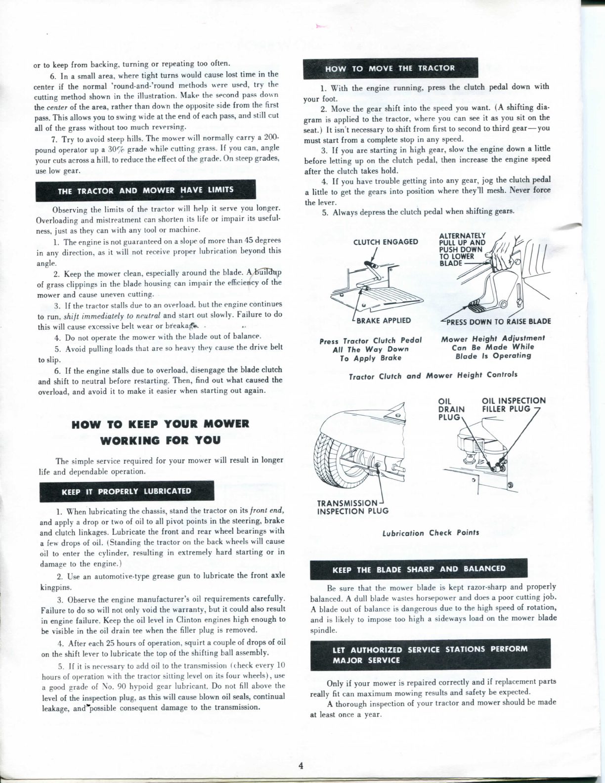
1.Withtheenginerunning,presstheclutchpedaldown
with
your
foot.
2.Movethe
gear
shiftintothespeedyouwant.(Ashifting
dia-
gramisappliedtothe
tractor,
whereyoucanseeit asyousitonthe
seat.)
Itisn'tnecessarytoshiftfromfirsttosecondtothirdgear—you
muststartfroma complete stopinanyspeed.
3.Ifyouarestartinginhighgear,slowtheenginedowna little
beforelettingupontheclutchpedal,thenincreasetheenginespeed
aftertheclutchtakeshold.
4.Ifyouhavetroublegettingintoanygear,jogtheclutchpedal
alittletogetthegearsintopositionwherethey'llmesh.Neverforce
thelever.
5.
Always
depresstheclutchpedalwhenshiftinggears.
CLUTCH
ENGAGED
ALTERNATELY
PULL
UPAND
PUSH
DOWN
TO
LOWER
BLADE
BRAKE
APPLIED
Press
Tractor
Clutch
Pedal
All The Way
Down
To
Apply
Broke
"^PRESS
DOWN
TO
RAISE
BLADE
Mower
Heighf
Adjustmertt
Can Be
Made
While
Blade
Is
Operating
Tractor
Clutch
andMower
Height
Controls
OIL
DRAIN
PLUG
OIL
INSPECTION
FILLER
PLUG
TRANSMISSION-
INSPECTION
PLUG
Lubrication
Check
Points
KEEPTHE
BLADE
SHARP
AND
BALANCED
Besurethatthemower bladeiskeptrazor-sharpandproperly
balanced.
A
dull
bladewasteshorsepoweranddoesa poorcuttingjob.
A
bladeoutofbalanceisdangerousduetothehighspeedofrotation,
and
is
likely
toimposetoohigha sidewaysloadonthemower blade
spindle.
LET
AUTHORIZED
SERVICE
STATIONS
PERFORM
MAJOR
SERVICE
Only
ifyourmowerisrepairedcorrectlyandifreplacementparts
really
fitcanmaximummowingresultsandsafetybeexpected.
A
thoroughinspectionofyour
tractor
andmower shouldbemade
atleastoncea year.
4

HOWTO
OPERATE
AND
MAINTAIN
YOUR
ELECTRIC
START
LAWN
MOWER
It
isnecessary tofollowtheseadditionalinstructions,ifyour
lawn
mowerisequipped
with
electricstarting.Followingtheseinstructions
will
assureyouofthebestcontinuedbenefitsofelectricstarting.
PREPARING
FOR
OPERATION
The
"dry-charged"batteryanditscontainerofelectrolyteare
shipped
inseparatecartonsinsidethemower carton.Yourdealer
should
haveactivated,connectedandinstalledthebattery.Incasethis
was
notdonebeforeyoureceivedthemower,activatethebatteryand
install
itasfollows:
1.Removethebatteryfromitscarton.Activateit bypouring
theelectrolyteintothecells.
Fill
each
cell
tothelevelofthecirclein-
dicatorinthe
fill
tube.Afterreplacingthe
cell
caps,removethepipe-
cleanerplugsfromthevents.
2.Setthebatteryonthefloor beside themower.Attachthered
cabletothered(positive)terminalofthebatteryandtheyellowcable
totheyellow(negative)terminal.Usethehardwarefurnished.
3.
Slide
thebatteryinto thebracketprovidedatthefrontofthe
mower,andtightenthehold-downclamp.
4.Checkthecharge
with
a
^attery
hydrometer.Ifthespecific
gravityisbelow1.265to
1.285,
havethebatteryslow-chargedata
2-amp.maximum
rate
until
the
full
chargeisreached.This is particu-
larly important for cold weather starting.
Careful
preparationoftheengine
will
preventoverloadingofthe
electricstartingequipment,and
will
provide
better
servicefromyour
mower.
1.Keepthecrankcase
filled
totheproper
level.
Iftemperature
is
above40°F,useNo.30weightregulargradeautomobileengineoil.
2.Ifthetemperatureisbelow40°F,disregardthenameplate
instructionsand
fill
thecrankcasetotheproperlevel
with
No.10
weight
regulargradeautomobileengineoil.
3.Usea regulargradeof
FRESH
gasoline.Keepthegasoline
tank
full
whenthemowerisnotinuse, tohelppreventwaterconden-
sation.
4.Besurethecarburetorisadjustedforeasiest starting.
STARTING
WITH
THE
ELECTRIC
STARTER
Becauseofsizerequirements,thestarterhascertainoperating
limits
andcoldweatherlimitations.Intemperaturesbelow20°F it
maybenecessary tostarttheengine
with
therecoilstarter.Seethe
special
instructionsforcoldweatherstarting.Innormaltemperatures,
startthemowerasfollows:
1.Besurethetransmissionisinneutralandthebladeclutchis
disengaged.
This
relievesthestarterofextraload.
2.Besuretheenginespeedcontrolleverissetproperlyforstart-
ing.
3.Iftheengineisagainstthecompression,
pull
itpastthecom-
pression
stroke
with
therecoilstarterrope.
4.
Turn
thekeytostartcrankingtheengine.
5.A self-resettingcutoutswitchpreventsdamagetothestarter
motor
fromover-heating.Continuouscranking
will
causethisswitch
toopen,stoppingthestarter.Ifthishappens,allow thestartertocool
until
theswitch
contacts
close.
COLD
WEATHER
STARTING
In
coldweather,followtheseinstructionsforstartingtheengine
ofyour
lawn
mower.
1.Followthe"PreparingforOperation"instructionscarefully.
2.Besurethebatteryisat
full
chargeandallconnections are
tight.
3.Asthetemperaturedrops,batteryefficiencyalsodrops,even
thoughthebatteryis
fully
charged.
This
increasestheamperagedraw
ofthestarter,andmaycausethecutoutswitchtoopenafteronlya
momentarycrankingperiod.
(This
isbecauseanelectric
motor
heats
rapidly
underabnormalamperageconditions.)Ifthishappensincold
weather,it usuallymeansthatthestarterhasreacheditscoldweather
limitations,
anddoesnotnecessarilyindicatea defectivestartermotor.
4.Inmoderatelycoldweather(about20°F),besuretheengine
speedcontrolleverissetproperly,andallloadisremovedfromthe
engine.Itmayalsobenecessarytoturntheenginethroughtwoor
threerevolutions
with
therecoilstartertobreaktheoil
film
sealsand
reducethefriction.
5.Iftheenginehasstoodidlefora prolongedperiodincold
weather,it
will
usuallyhavetobestarted
with
therecoilstarter.
PROTECT
THE
STARTER
THROUGH
PROPER
USE
To
preventdamagetothestarter
motor
andbattery,usethestarter
carefully,
accordingtothefollowingcautions.Thewarrantyisvoid
if
thetimelimitsaredisregarded.
1.Neverrunthestarterformorethantensecondscontinuously.
2.
Allow
one
full
minutebetweenten-secondcrankingperiods.
3.Donotrepeattheten-second crankingperiodmorethanfive
times.Iftheenginedoesnotstart
within
fivecrankingandwaiting
periods,
thereisa mechanicalreason.Checkandcorrect.
4.
Allow
fifteen minutesbeforetryingtostarttheengine,after
using
upthefive 10-second crankingintervals.Failuretoobservethese
timelimitscausesexpensivepermanentdamagetothestartermotor.
TAKE
GOOD
CARE
OFTHE
ELECTRICAL
SYSTEM
Proper
care
oftheelectricalsystem
will
resultinlonglifeofthe
partsandgoodservicefromtheelectricstarter.
1.Checkthebatteryoncea monthfor
state
ofcharge.Recharge
thebatteryifthespecificgravityofthecellsfallsbelow
1.225,
orif
theopencircuitvoltageofthecellsdropsbelow2.04volts.Usea maxi-
mum
charging
rate
of2 amps.Keepbatteriesatornear
full
charge
forbestperformance.
2.Whilethebatteryisinuse, checkit oncea weekforelectro-
lyte
level.
Keeptheelectrolyteabovetheseparators,but
fill
onlyto
thecircleindicator,notinto thevent tube.Useonlydistilledorap-
provedwaterfor
filling.
3.Donotaddbatterydopes,additives,oracid.Suchadditions
void
thebatteryguarantee.
4.Keepthebatterycleanbybrushingoffdirt,dustandgrass
clippings
afteruse.Ifcorrosiondevelopsontopofthebattery,clean
it
with
waterandbakingsoda.Besuretokeepthevent plugsinthe
cells
while
cleaning.Coatthecleanedterminals
with
petroleum
jelly
(Vaseline)
topreventfurthercorrosion.
5.Batteriesmaybestoredwithoutdamageiftheyarefully
5
ATTACHMENTS
INCREASE
YOUR
MOWER'S
USEFULNESS
charged
whenplacedinstorage.Storeina dryplace,wherethetem-
peratureisbetween32°F and60°F.Keepthebatteryawayfrom
extreme
heatorcold.Rechargethebatterybeforeplacingit inservice.
6.Checkstoredbatteries everytwomonthsduringstorage.Re-
chargeimmediately,iftheopencircuitvoltagedropsbelow2.04volts,
orthespecificgravitydropsbelow
1.225.
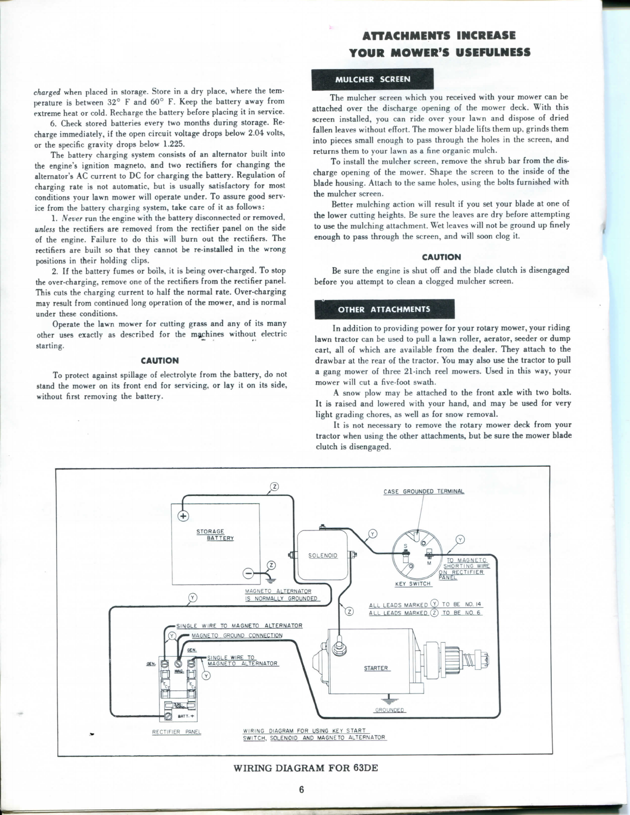
The
batterychargingsystemconsistsofanalternatorbuiltinto
theengine'signitionmagneto,andtworectifiersforchangingthe
alternator'sACcurrenttoDCforchargingthebattery.Regulationof
charging
rate
isnotautomatic,butisusuallysatisfactoryformost
conditionsyour
lawn
mower
will
operate
under.Toassuregoodserv-
icefromthebatterychargingsystem,take
care
ofit asfollows:
1.Never runtheengine
with
thebatterydisconnectedorremoved,
unless therectifiersareremovedfromtherectifierpanelontheside
oftheengine.Failuretodothis
will
burnouttherectifiers.The
rectifiersarebuiltsothattheycannotbere-installedinthewrong
positionsintheirholding
clips.
2.Ifthebatteryfumesorboils,itisbeingover-charged.Tostop
theover-charging,removeoneoftherectifiersfromtherectifierpanel.
This
cutsthechargingcurrenttohalfthenormalrate.Over-charging
mayresultfromcontinuedlong operationofthemower,andisnormal
undertheseconditions.
Operatethe
lawn
mowerforcuttinggrassandanyofitsmany
otherusesexactlyasdescribedforthemachineswithoutelectric
starting.
CAUTION
To
protect
againstspillageofelectrolyte fromthebattery,donot
standthemoweronitsfront endforservicing,orlayit onitsside,
without
firstremovingthebattery.
MULCHER
SCREEN
The
mulcherscreen
which
youreceived
with
yourmower canbe
attachedoverthedischargeopeningofthemowerdeck.Withthis
screeninstalled,youcanrideoveryour
lawn
anddisposeofdried
fallen
leaveswithouteffort.Themower bladeliftsthemup,grindsthem
into piecessmallenoughtopassthroughtheholesinthescreen,and
returnsthemtoyour
lawn
asa fineorganicmulch.
To
install
themulcherscreen,removetheshrubbarfromthe
dis-
chargeopeningofthemower.Shapethescreentotheinsideofthe
bladehousing.Attachtothesameholes,usingtheboltsfurnished
with
themulcherscreen.
Bettermulchingaction
will
resultifyousetyourbladeatoneof
thelowercuttingheights.Besuretheleavesaredrybeforeattempting
tousethemulchingattachment.Wetleaves
will
notbeground upfinely
enoughtopassthroughthescreen,and
will
soonclogit.
CAUTION
Besuretheengineisshutoffandthebladeclutchisdisengaged
beforeyouattempttocleana cloggedmulcherscreen.
OTHER
ATTACHMENTS
In
additiontoprovidingpowerforyourrotarymower,yourriding
lawn
tractor
canbeusedto
pull
a
lawn
roller,
aerator,
seederordump
cart,allof
which
areavailablefromthedealer.Theyattachtothe
drawbarattherearofthe
tractor.
Youmayalsousethe
tractor
to
pull
agangmowerofthree21-inchreelmowers.Usedinthisway,your
mower
will
cuta five-footswath.
A
snowplowmaybeattachedtothefrontaxle
with
twobolts.
It
israisedandlowered
with
yourhand,andmaybeusedforvery
light
gradingchores,as
well
asforsnowremoval.
It
isnotnecessarytoremovetherotarymowerdeckfromyour
tractor
whenusingtheotherattachments,butbesurethemowerblade
clutch
isdisengaged.
CASE
eWOUNDED
TERMINAL
STORAGE
BATTERY
4c <[
SOLENOID
//
TQ
MASNETQ
SHORTING
WIRE
®
MAGNETO
AlTERNATOR
15
NORMALLY
GROUNDED
•SINGLE
WIRE
TO
MAGNETO
ALTERNATOR
[Y)^MAgNETO
GROUND
CONNECTION
-SINGLE
WIRE
TO
MAGNETO
ALTERNATOR
GROUNDED
RECTIFIER
PANEL
WIRING
DIAGRAM
FOR
USING
KEY
START
SWITCH.
SOLENOID
AND
MAGNETO
ALTERNATOR
WIRING
DIAGRAM
FOR63DE
6

MAINTENANCE
TIRE
PRESSURE
Themowers
use
pneumatictires
and
tubes
onthe
back
wheels.
The
32-inchmower
alsouses
pneumatic
tires
and
tubes
onthe
frontwheels.Keep
the
rear
pneumatictiresinflated
toa
maximum
of30
pounds
pressure.Maximumpressure
forthe
fronttires
is
45
pounds.
(The
25-inchmower
uses
semi-pneumatic
tiresonthefrontwheels.
These
tires
will
not
require
inflation.)
LUBRICATION
The
following
chartshows
all
lubricationpoints,
with
thetype
of
lubricant
touseoneach.
Lubrication
times
inthe
chartrefer
to
hours
of
operation.Lub-
ricatemoreoften
ifthe
mower
is
used
in
exceptionally
dusty
areas.
Note
that
the
ClintonEngineused
onsome
models
ofthemower
has
no
dip
stickforcheckingoil.Instead,
to
checktheoil,
remove
the
plug
from
thetopofthe
pipe
tee
which
is
installed
nearthe
front
ofthe
engine,
on
the
right
handside
ofthe
tractor.
Ifoilis
visible
in
the
bottom
ofthetee
when
the
tractor
isona
level
surface,there
is
sufficient
oilinthecrankcase.
In
addition
to
thelubricationproceduresdescribed,
it
isa
goodidea
to
clean
all
lubricationpoints
ofthe
tractorandmoweroccasionally,
to
prevent
build-up
of
dust
and
foreignmatter
onthe
parts.
ADJUSTMENTS
Adjustmentsrequiredforthemower
are
simple
and
infrequent.
Spring-loadedidlers
onthe
mainblade
drive
belt
(andonthe
bladedrivebelts
ofthe
32-lnch
mowerattachment)maintainpropertension
forthese
belts
so
thatadjustment
isnot
required
for
them.
Adjust
the
brakebandbytightening
or
loosening
the
lock
nutonthe
rear
endofthe
brake
rod.
STEERINGHANDLEBARS
GEARSHIFTLEVER
STARTER
ROPE
HANDLE
ENGINESPEED
CONTROLLEVER
LEVELING
WHEELS •ELECTRIC
STARTKEY
STEERING
HANDLEBARS
FUEL
TANK
VALVE
TRACTORCLUTCH
ANDBRAKEPEDAL
STARTER ROPEHANDLE
GEARSHIFTHANDLE
BLADECLUTCH
LEVER
BLADE
CLUTCH
LEVER
*ElectricStartModelsOnly
BLADE
HEIGHT
ADJUSTMENT
GEARSHIFTLEVER
ENGINESPEED
CONTROLLEVER
kPosifionsof
Engine Speed
Control
Lever
Figure
1.
Controls
for
Tractor
and
Mower
7
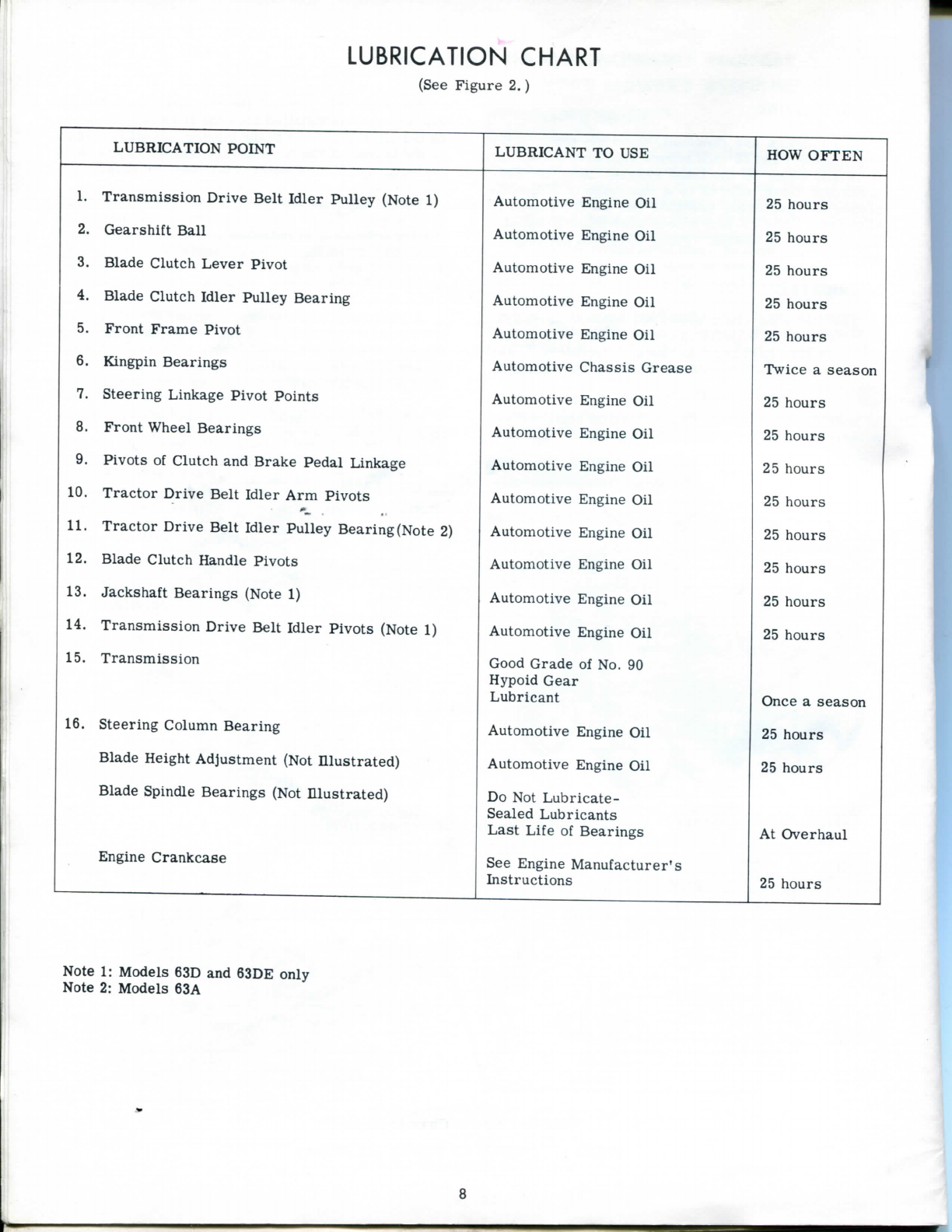
LUBRICATIONCHART
(See
Figure
2.)
LUBRICATION
POINT
LUBRICANT
TOUSE
HOW
OFTEN
1.
TransmissionDriveBeltIdlerPulley(Note
1)
Automotive
Engine
Oil
25hours
2. GearshiftBall
Automotive
EngineOil 25hours
3. BladeClutchLeverPivot
Automotive
Engine
Oil
25hours
4. BladeClutchIdlerPulleyBearing
Automotive
Engine
Oil
25hours
5.
Front
FramePivot
Automotive
Engine
Oil
25hours
6.
Kingpin
Bearings
Automotive
Chassis
Grease
Twice
a
season
7. SteeringLinkagePivotPoints
Automotive
Engine
Oil
25hours
8.
Front
Wheel
Bearings
Automotive
EngineOil 25hours
9. Pivots
of
ClutchandBrakePedalLinkage
Automotive
Engine
Oil
25hours
10. TractorDriveBeltIdlerArmPivots
Automotive
Engine
Oil
25hours
11.
TractorDriveBeltIdlerPulleyBearing(Note
2)
Automotive
Engine
Oil
25hours
12. BladeClutchHandlePivots
Automotive
Engine
Oil
25hours
13.
Jackshaft
Bearings
(Note
1)
Automotive
EngineOil 25hours
14. TransmissionDriveBeltIdlerPivots(Note
1)
Automotive
Engine
Oil
25hours
15. Transmission GoodGrade
of
No.
90
Hypoid
Gear
Lubricant
Once
a
season
16. SteeringColumnBearing
Automotive
Engine
Oil
25hours
BladeHeightAdjustment(NotIllustrated)
Automotive
Engine
Oil
25hours
BladeSpindle
Bearings
(NotIllustrated)
Do
NotLubricate-
Sealed
Lubricants
LastLife
of
Bearings
At
Overhaul
Engine
Crankcase
See
EngineManufacturer's
Instructions
25hours
Note
1:
Models
63Dand
63DE
only
Note
2:
Models
63A
8
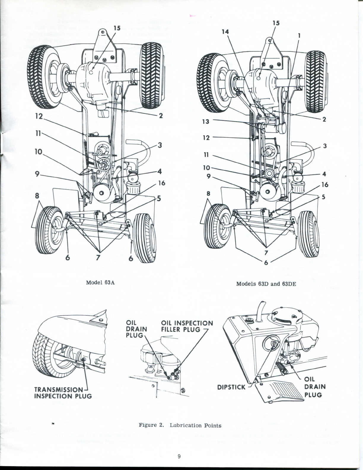
Model
63A
Models
63D
and
63DE
9
Carburetoradjustments
are
covered
inthe
engine
manufacturer's
instruction
manual,
which
is
furnished.
No
otheradjustments
are
required
forthe
mower.
WINTERIZATION
Winterization
for
Storage
When
itis
time
to
store
the
mower
forthe
winter,
clean
it
thoroughly
ofall
grass
clippings,
mudand
dust.
Wipe
all
lubricationpointsclean
and
lubricate.
Drain
thegasoline
from
the
fuel
tankandthecarburetor,
to
prevent
formation
of
gummydeposits.
Drain
theoil
from
the
engine
crankcase,
and
refill
with
the
grade
of
oil
which
is
recommended
for
warm-weatheropera-
tion.
Drain
and
refill
the
transmissionhousing,using
thegrade
ofoil
recommended
for
summer
use.
CAUTION
Do
not
over-fill
engine
or
transmission.
Stand
the
tractor
onits
front
end
(removebattery
from
electricstarttractors),
and
remove
the
spark
plug.
Put
about
oneto
twotablespoons
of
engine
oil
into
thespark
plug
hole,
slowly,
while
turning
theen-
gineslowly
by
hand
to
allow
the
piston
to
distribute
the
oil
evenlyover
the
cylinderwalls.
Replace
the
spark
plug
with
an
old
plug
which
will
notbe
usedagain,
or
plug
the
hole
with
a
cork.(Thisprevents
fouling
thegood
plug
with
theoilused
to
preserve
the
cylinder
and
piston.)
CAUTION
Always
remove
the
battery
from
electricstart
tractorsbeforestandingthem
onendfor
serv-
ing.
Replace
the
batterybeforeattempting
to
operate
the
engine.
In
thespring,removetheoldspark
plug
orthe
cork,
flush
the
cylinder
with
about
1/4to1/2cupof
fresh
gasoline
and
blowdry
with
compressed
air.
Replace
thegoodspark
plug,
afterbeingsure
itis
clean
and
properly
gappedaccordingtotheenginemanufacturer's
instructions.
Check
theoilinthe
engine
and
trans-
mission.
Fill
the
fuel
tank.
The
tractor
is
nowready
for
operation.
Winterization
for
Operation
If
thetractor
is
to
be
used
during
the
wintermonths,
cleanandlubricateinthe
same
manner
asfor
storage.
Drain
thetransmission
and
refill
with
a
goodgrade
of
No.
50
non-detergentmotoroil.
Drain
the
engine
crankcase
and
refill
with
oilas
recommended
bythe
manufacturerforthetemperaturerangeexpected.
Be
sure
the
spark
plug
is
clean
and
properlygapped
ac-
cording
tothe
enginemanufacturer'sinstructions.
In
thespring,
drain
and
refill
the
transmission
and
engine
crankcase
with
the
normally-recommended
weights
of
oil,
andservicetheentiretractorcarefully,
according
tothe
instructions
in
thismanual.
BLADE
MAINTENANCE
It
is
importantthat
the
blades
be
keptrazor-sharp
andin
balance.
Dull
bladeswastepower,
anddoa
poor
grass-cuttingjob.
Blades
which
are
out
of
balance
im-
pose
too-high
a
sidewaysload
on
theirbearings,
and
cause
dangerousvibrations.
When
sharpeningblades,alwaystakeequalamounts
ofmetal
off
both
cutting
edges.
Replace
blades
which
show
any
signs
of
cracks
or
crystallization,
to
prevent
their
disintegration
at
high
rotating
speeds.
Inexpensiveblade
balancers
are
available,to
assure
that
the
blades
arein
balance
aftersharpening.
In
case
sharpeningresults
inan
out-of-balanceblade,
grind
some
moremetal
off
heavy
end.
Remove
and
replace
the
blades
as
describedunder
"Removal
and
Replacement
of
Parts".
REMOVALANDREPLACEMENTOFPARTS
CAUTION
Beforeperforming
any
serviceoperations
on
themower
, be
sure
to
disconnect
the
spark
plug
wire
to
preventaccidentalstarting
ofthe
engine.REMOVEBATTERY
from
electric
starttractors.
BLADES
25-InchBlade
Stand
the
tractor
onits
front
end.
Disengage
the
bladeclutch,
so
that
the
bladebrake
keeps
the
spindle
from
turning.
Remove
the
blade
by
removing
the
spindle
nut,
which
hasa
right-handthread.Note
the
positions
ofthe
twolargewashers
andone
small
flat
washer,
as
theymustbereplacedinthe
same
positions.
When
replacing
the
blade,refer
to
figure
3.Be
sure
the
blade
is
installed
right
sideup.
If
installed
upside
down
it
will
notcut
and
will
consume
too
much
horsepower.Tighten
the
spindle
nut
thoroughlyafter
replacing
the
blade.
32-Inch
Blades
The
3
2-inchmower
uses
two
blades.Standthetrac-
tor
onits
front
endand
disengage
the
bladeclutch
to
10

Figure3.Installationof
Blades
apply
thebraketothebladedrivespindle.Inserta
drift
pinorotherblockingdeviceintotheholeinthe
mowerdeck,
adjacent
to
each
oftheblades,toprevent
the
blades
from
turning.
(Seefigure4.)
Remove
the
blades
bytakingofftheright-hand
threadedspindlenuts.Notethepositionsofthelarge
and
smallflatwashers,as
these
mustbereplacedin
the
same
positionswhenthebladeisreinstalled.
Besurethe
blades
areinstalled
right
sideup.See
Figures.Usetheblockingpinsto
keep
the
blades
from
turning
whenretighteningthespindlenuts.
MOWERATTACHMENT
Usea 1/2-inchwrenchtoloosenthefourbolts
which
hold
themowerdecktothe
sides
ofthetractor
chas-
sis.Standthetractoronitsfrontendandremovethe
four
bolts.Graspthemowerattachmentbythe
cen-
teroftheblade,andbytherear
cross-bar
ofthe
heightadjustmentmechanism,toremoveit.
NOTE
Toprevent
loss
ofthefourbolts,ifthetrac-
tor
istobeused
without
themowerattach-
ment,reinstallthemintothe
holes
and
tight-
en.Donotover-tighten.
Toreinstallthemowerattachment,againstandthe
tractoronitsfrontend.Loosenthefourbolts
holding
thebladedrivepulleytothe
chassis.
Graspthemow-
erattachmentbytherear
cross-bar
andthe
center
of
theblade.
Turn
thebladeslightlyto
engage
thehex-
agonaltopofthespindleintothehexagonalholeinthe
bottom
ofthebladedrivepulleyonthe
chassis.
Slide
thesideplatesofthemowerattachmentoverthe
sides
ofthe
chassis,
andattach
with
thefour5/16-inchbolts.
Retightenthefourbolts
holding
thedrivepulleytothe
Figure4.LockingBladePulleytoLoosenBladeNut
chassis.
This
centers
thepulley
with
respect
tothe
mowerattachment.
Themowerattachmentmaybeleftin
place
forall
attachmentsbutthesnowblade.
TRACTORDRIVE
BELTS
NOTE
It
is
necessary
toremovethemowerattach-
mentbeforereplacinganyofthebelts.
TractorDriveBelt(Model63A)
With
thetractorstandingonitsfrontend,
depress
theclutchpedalasfarasit
will
go.This
takes
the
tensionoffthetractordrivebelt.
Wring
thebeltoff
theenginepulley,
disengage
it
from
thebeltguides,
and
removeit
from
thetransmissionpulley.(Notice
thedirectionof
twist
ofthebelt,9othatyoucanrein-
stall
itmoreeasilyinthe
same
pcJSition.)
Seefigure5.
Figure5 InstallationofTractorDriveBelt
(Model
63A)
11

TRANSMISSION
DRIVE
BELT
JACKSHAFT
DRIVEN
PULLEY
TRACTOR
DRIVE
BELT
IDLER
PULLEY
TENSION
SPRING
TRANSMISSION
DRIVE
PULLEY
CLUTCH
IDLER
PULLEY
JACKSHAFT
DRIVE
PULLEY
BELT
GUARD
TRACTORDRIVE
BELT
IDLER
PULLEY
ENGINE
PULLEY
LEFT
HAND
BLADE
RIGHT
HAND
BLADE
DRIVE
BELT
ANDDRIVE
BELT
PULLEY
ANDPULLEY
SHAFTADAPTERAND
MAIN
BLADEDRIVE
PULLEY
SPRING-LOADEDIDLERS
Figure
7.
BladeDrive
Belts
on
32-InchMowerAttachments
Figure
6
Installation
of
TractorDrive
Belts
(Models
63Dand
63DE
)
To
replace
the
tractordrivebelt,
place
it
over
the
transmissionpulley
first,
thenthrough
the
rearbelt
guide.
Twistthebelt
which
leads
offthe
bottom
ofthe
transmissionpulleyone-half
turn
tothe
left
and
place
it
onthe
outside
ofthe
middlebeltguide.Twist
the
belt
which
leads
offthetopofthe
transmissionpulley
one-half
turn
totheleft,
and
place
it
behind
the
middle
beltguide(between
the
beltguide
andthe
bladeclutch
mechanism).
Wring
thebeltaround
the
enginepulley.
The
veeofthe
beltshould
fit
into
the
groove
ofthe
enginepulley.
Engage
the
belt
onthe
clutchidler
pulley,
so
thattheidlerpulleyrides
onthe
rear
ofthe
belt.
(Notethat
the
clutchidlerpulley
is
mounted
onits
bracket
with
a
slight
tilt,
in
order
to
properlyguide
and
engage
thebelt.This
tilt
is
intentional,
and
should
not
be
disturbed.
See
figure
5.)
TractorDriveBelt(Models
63Dand63DE)
Disconnect
the
spring
which
appliestension
tothe
idler
pulley
forthe
tractordrivebelt.
Wring
the
belt
off
theenginepulley.Whenremoving
the
belt,notice
thedirection
of
twist,
so
that
the
belt
canbe
replaced
in
thesame
manner.
Replace
the
belt
by
installing
it
over
the
jackshaft
driven
pulley
first,
then
twisting
thetop
side
ofthe
beltone-quarter
turn
tothe
left
so
that
theveeofthe
belt
will
runintothegroove
ofthe
enginepulley,
atthe
right.
Wrfng
the
beltinto
the
groove
ofthe
engine
pulley.
Thebeltshouldrun
offthe
leftside
oftheen-
ginepulley
tothe
bottomside
ofthe
jackshaft
driven
pulley.
See
figure
6.
TransmissionDriveBelt(Models
63Dand
63DE)
Remove
the
beltguard
which
partiallysurrounds
thejackshaftdrive
pulley.
Donotmisplacethisguard,
asitis
essential
that
itbe
replacedafterreplacing
thebelt.
Depress
theclutchpedal,
to
take
the
tension
off
the
transmissiondrivebelt.
Wring
the
belt
off
either
the
jackshaftdrivepulley
orthe
transmission
pulley,
to
remove
it
from
the
tractor.
Reinstallation
ofthe
transmissiondrivebelt
isthe
reverse
of
removal.
Be
sure
to
replace
the
beltguard,
to
keep
the
belt
in
place
during
timeswhen
the
clutch
pedal
is
depressed.
Mower
DriveBelt(AllModels)
Remove
the
tractordrivebelt
as
describedabove,
for
access
tothe
mowerdrivebelt,thenremove
the
5/16
inchbolt
which
holds
the
bladeclutchidler
arm
to
the
tractor
chassis.
Wring
the
mowerdrivebelt
overthemowerdrivepulley
and
remove
from
theen-
ginepulley.
Replace
thebelt
first
ontheengine
pulley,
then
wring
it
onto
the
mowerdriveadapterpulley.
Replace
the
linkageandsprings
which
weredisconnected.
Replace
thetractordrivebelt
as
describedabove.
Blade
Belts
(32-lnchMowerAttachment)
Remove
the
right-hand
and
left-handpulley
covers
for
access
tothebladedrivebelts.
See
figure
7.Un-
12

hook
thesprings
from
theidlers.
Wring
thebeltsoff
theoutsidepulleys
first,
thenremovethem
from
the
center
pulley.
Replace
inthereverseorder.Besure
to
hookthesprings
into
theidlerarms.
Replace
the
pulley
coversafterthebeltshavebeenreinstalled.
BEARINGS
Rear
AxleBearings
Rear
axlebearingsoftheModels63A,63Dand
63DE
arecontainedinextensionsofthetransmis-
sion
housing.Theyarelubricated
from
within
bythe
transmissionlubricant,andcanbereplacedonlyon
completedisassemblyofthetransmission.
BearingsofBladeDriveSystem
Thebearingsoftheblade
drive
systemaremount-
edinhousings
which
areboltedtothetractor
drive
chassis
orthemowerhousing.
These
arelocatedas
describedbelowforthetwo
sizes
ofmowers.Ifre-
placementofthebearingsoftheblade
drive
systemis
required,
removethebelts
from
aroundtheaffected
pulleys,
andremovethebladeifa bladespindle
bear-
ing
istobereplaced.
Refer
totheexplodedviews
which
illustratetheparts
list,
fordisassembly.
Locationsofthebearingsofthe-blade
drive
system
areas
follows:
Both
models:Blade
drive
adapter,locatedin
center
of
chassis,
underneath.
25-Inch
Model:
Bladespindle,locatedin
center
of
mower
housing.
32-InchModel: Twobladespindles,locatedon
mower
housing
toward
outside
from
center.Blade
pulley
spindle,locatedin
center
ofmowerhousing.
If
itis
necessary
to
drive
thebearingsoutoftheir
housings,applyforceonlyonthe
races
which
are
tight
in
thehousingsorontheshafts.Donottransmit
removing
orinstalling
forces
throughtheballsor
rollers.
Usea soft-headed(leather,rubberorplastic)
mallet
to
drive
bearings
into
oroutofposition.
TRANSMISSIONANDENGINE
If
thetransmissionshouldrequirerepair,contact
the
closest
authorizedservicestation,orthe
nearest
centraldistributoraslistedon
page
24ofthisbook.
Toremovethetransmission
from
thetractor
chas-
sis,
first
removethetransmission
drive
beltanddis-
connectthebrakerod
from
thebrakeband.Remove
thenuts
from
thetwoU-bolts
which
fastentheaxle
housingstothewheelsupportbrackets.Takeoutthe
four
bolts
which
attachthetransmissionhousingtothe
tractor
chassis.
Thisallowsthetransmission,com-
plete
with
rearaxlehousingsandwheels,tobere-
moved
from
thetractor.
Toremovetheengine,takeoffthehood,handle
bars,and
drive
belts.(The
fuel
tanktorLausonen-
ginemodels
will
come
off
with
thehood.)Removethe
enginepulleybytakingoutthe3/8-inchbolt
which
is
threaded
into
thebottomoftheenginecrankshaft.Do
not
lose
ordamagethekey
which
locksthepulleytothe
enginecranksahft.Disconnecttheexhaustpipecou-
pling
nut.
Removethefour5/16-inchbolts
which
fasten
theenginetotheenginemountingplate,and
lift
the
engine,
with
carburetorand
fuel
system,offthetopof
the
chassis.
Donot
lose
thebeltguide
which
isattached
by
twooftheengine
mounting
bolts.Itisnot
necessary
to
removetheexhaustpipe
from
the
chassis.
Repairoftheengineshouldbeaccomplishedbyone
oftheenginemanufacturer'sauthorizedservice
sta-
tions.
MISCELLANEOUSPARTS
Follow
theexplodedviews
which
accompanythere-
placementparts
list
ifanyotherpartsaretobere-
placed.Orderallreplacementparts
from
the
closest
Quick
Mfg.,Inc.centralparts
distributor
showninthe
list
insidethebackcoverofthisbook.Givecomplete
information,
including
themodelnumberofthemower,
and
thepartnameandcorrectpartnumberofthere-
placementparts
list
andaccompanyingexplodedviews.
Figures8 through14showallofthereplaceable
partsofthetractors,explodedfor
easy
identification.
REPAIRPARTSLIST
The
illustrations
and
partslists
which
follow
show
all
ofthereplaceablepartsofyour
riding
rotary
lawn
tractor.
The
illustrations
showthetractordismantled
into
itsmajorcomponents,
with
each
partindexed.
If
youshould
find
it
necessary
toreplacea part,
find
the
illustration
which
showsthesectionofthe
mower
which
containsthepartyouneed;then
find
the
part
inthe
illustration
andnoteits
reference
number.
Turn
tothe
listing
ofpartsforthe
illustration,
and
find
the
reference
numberassignedtothepartyou
need.
Read
across
thelinetodeterminethenameand
part
numberofthepart.
Order
thepartsyouneedby
NAME
ANDPART
NUMBER
ONLY.Donotusethe
reference
numbers.
13

REPAIR
PARTS
LIST
Figure
8.FrontEndAssembly(AllModels)
Ref. Part PartNameor
Quantity
Ref. Part PartNameor
Quantity
No.
Number Description
25" 32"
No.
Number Description
25"32"
1
57155
Fender
front
2 2 8
57985
Nut,
Hex 22
2
57102
Bolt,
Sems
unit
. , , . 4 4 9 1806 Lockwasher.... 22
3
55033
PotterDin 5 5 10
57971
Pin
22
w
4 1018 Washer 6 6 11 60A-39
Rod,
Tie
1
1
5
57150
WheelAssy,
front
. . 2 12 Y60A-44
Axle
assy,
front,
R.H.
1
1
57150-1
2 -13 Y60A-43
Axle
assy,
front,
L.H.
1
1
6 Y60D-22 Wheel
assy,
front,incl.
-2 14
57137
Housing,front
axle
1
1
60D-23
-2 15 57116
Grease
fitting
. . . 22
60D-24
Tube. . _ 2 16
57961
Screw
1
1
60D-25
_ 2 17 1022 Washer,
flat
....
1
1
«0D-21 -2 18
57962
Nut,
castellated. .
1
1
7 59A-70
Ball
joint
(steering
link)
19 57980 22
1 1
14

Figure
9.
25-Inch
Mower
Attachment
Ref.
No.
Part
Number
Part
Name
or
Description
Quantity
25" Ref.
No.
Part
Number
Part
Name
or
Description
Quantity
25"
1
57101
Bolt,
Sems
unit
....4
259A-153
Nut,
lock
1
3
57206
Washer,blade,special
2
4
60F-43
Blade
1
5
1018
Washer,special
flat.
. 1
660A-41
Bar,
shrub
1
7
59074
Bolt
4
859A-149
Nut,
lock
4
9
57222Pad,
foot
2
1057252
Bracket,mower
mounting,
L.
H.
. . 1
11
57250
Bracket,mower
mounting
R.
H.
• •
1
1260A-30Ratchet,
lift
1
1357284
Decal,
cutting
height
. 1
1455024Pin,
lock
1
1557266
Lift
pawl
assembly..
. 1
1657145
Knob
1
17
57267Nut,
pawl
slide
1
1857294
Lockwasher
1
19572^5Nut1
2057010
Screw
1
21
57912Pin,
lift
2
22
55033
Cotter
pin6
231018
Washer,special
flat.
3
2457256
Shaft,
lift
1
2557282
Washer,special
...1
2657257
Link,
lift
2
27
55054
Snap
ring
4
2857258
Bellcrank,
lift
4
2955024Pin,
lock
4
3057254
Shaft,
front
pivot
...1
31
57255
Shaft,rear
pivot
...1
32Y60A-18Bracket
assy,
lower
L.
H.
1
33
Y60A-17Bracket
assy,
lower
R.
H.
1
34 57228
Bolt,Specialcarriage
10
35
59A-150
Nut,
lock
10
36
62A-54
Housing,
spindle
...1
37
57281
Bearing
2
38
62A-55Spindle
1
39
62A-56
Spacer1
40 57276
Washer
1
41
63A-3Bolt
4
4259A150
Nut,
lock
4
43
60A-40
Housing,
mower.
...1
44
60A-36Leaf
Mulcher
1
15


Parts
Listing
for32-Inch
Mower
Attachment
Ref.PartPartNameor
Quantity
No.
NumberDescription32"
1
57101Bolt,
Sems
unit
4
259A-153Nut,lock2
3
57206
Washer,blade,special4
460D-50Blade2
51018Washer,special
flat
. . 2
660D-42Bar,shrub1
7
59074
Bolt4
859A-149Nut,lock4
960D-13Pad,
foot
2
1060D-41Bracket,mower
mounting,
L.
H.
. . 1
11
60D-34Bracket,mower
mounting,
R.
H.
. . 1
1260A-30Ratchet,
lift
1
13
57284
Decal,
cutting
height.. 1
14
55024
Pin,lock1
15
57266
Pawl
assembly,
lift
. . 1
16
57145
Knob1
17
57267
Nut,
pawl
slide1
18
57294
Lockwasher1
19
57295
Nut1
20
57010
Screw1
21
57912
Pin,
lift
' 2
22
55033
Cotterpin8
231018Washer,special
flat.
. 4
24
57256
Shaft,
lift
1
25
57282
Washer,special....1
26
57257
Link,
lift
2
27
55054
Snap
ring
4
28
57258
Bellcrank,
lift
4
29
55024
Pin,lock4
30
57254
Shaft,
front
pivot
....1
31
57255
Shaft,rear
pivot
....1
32Y61D-11Bracket
assy,
lower
L.
H.
1
33Y61D-12Bracket
assy,
lower
R.
H.
1
34
57228
Bolt,Specialcarriage.10
3559A-150Nut,lock10
3660D-31Pulleycover,L.
H.
. . 1
3760D-32Pulleycover,R.H...1
38
59049
Pulley,
idler
2
39
57247
Nut2
40
59050-2
Bushing2
41
60D-58
Spacer
1
42Y60D-61Bracket,
idler
2
43
59076
Bolt2
4459A-150Nut,lock2
45
55057
Washer,
flat
2
4661D-40Spring2
47
61TR-83
Belt,L.H 1
Ref.
Part Part
Nameor
Quantity
No.
Number Description
32"
48 61D-35
1
49 60D-48
Pulley
2
50 2111 Screw,Set 2
51
1018 Washer,special
flat
3
52 57011 2
53
57276
Washer,special. . 2
54 62D-13
Spindle
housing
1
55 62D-13
Spindle
housing X
56
57281
4
57 60D-38 Bladeshaft,L.
H..
.
1
58 62D-15 Bladeshaft,R.
H..
.
1
59 63A-3
60 59A-150
61
61D-34
1
62
61TR-129
Woodruff
key....
1
63 1020
1
64
57980
Cotter
Pin
65
57264
Housing,
bearing. .
1
66 1217 Washer
1
67
57263
1
68 Y61D-10
Spindle,
center. . .
(Universal
joint).
1
69
57960
Screw,self-tapping,
Sems
4
70 Y61D-8
Housing
assembly..
1
71
60D-20 LeafMulcher. . . .
1
72
61TR-82
Shaft,
roller
1
73 61TR-81
Roller
1
74 Y60D-105Wheelassembly,L.
H.,
1
Consistsof:
Y60D-106. Bracket,L.H.. .
56004
.
Axle
56014
. Wheel
59A-151. Nut
Y60D-103Wheelassembly,R.
H.,
Consistsof:
Y60D-104. Bracket,R.
H.
. .
56004
.
Axle
56014
. Wheel
59A-151. Nut
751046Bolt
7659A-149. Nut
NR
Y60D-44CompleteSpindle
Assy,
L.H
NR
Y60D-45CompleteSpindle
Assy,
R.H
NR
61TR-244
Plug,
Button
7762D-14
Spacer
17

Figure11.ExplodedViewof
Chassis
Assembly
(Model63A)
18
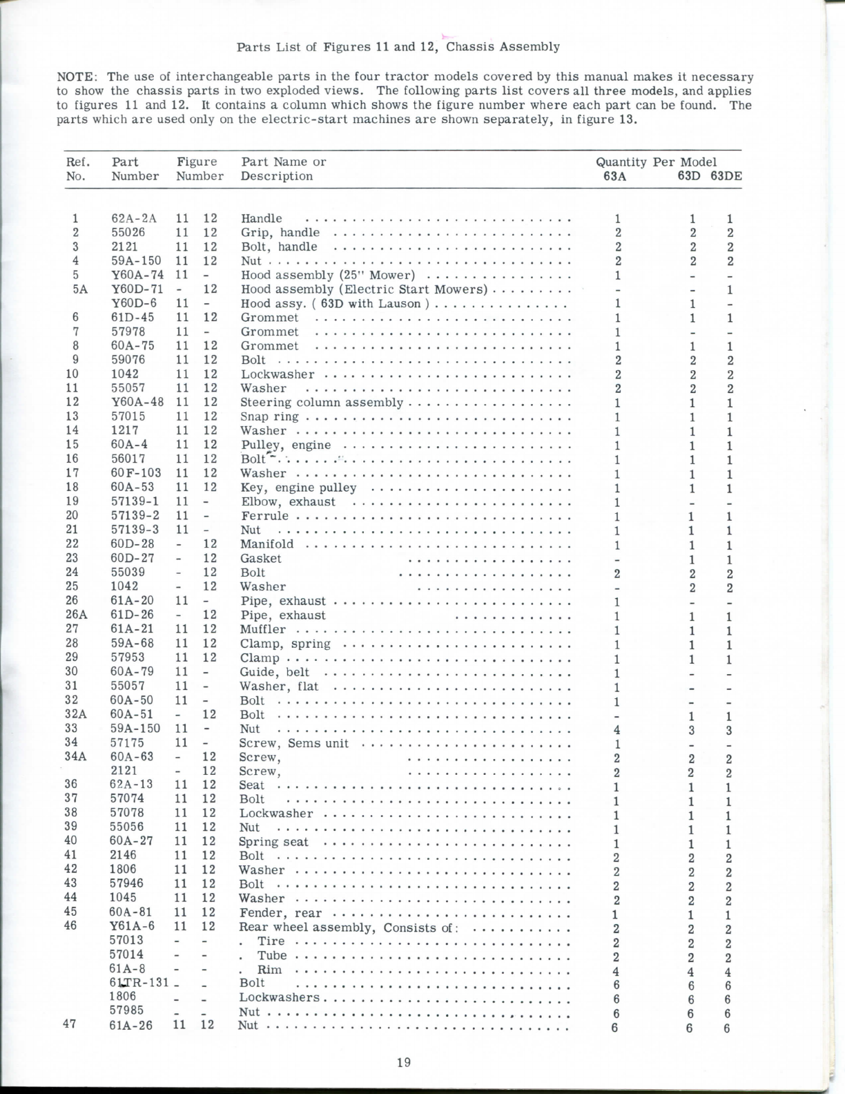
Parts
List
of
Figures
11and12,Chassis
Assembly
NOTE:
Theuse of
interchangeableparts
inthe
four
tractormodelscovered
by
this
manualmakes
itnecessary
to
show
thechassis
parts
in
twoexploded
views.
The
following
parts
list
coversallthreemodels,andapplies
to
figures
11and12.It
contains
a
column
which
shows
the
figure
numberwhereeach
part
can be
found.
The
parts
which
are
used
only
onthe
electric-startmachines
are
shown
separately,
in
figure
13.
Ref.PartFigurePartName
or
Quantity
Per
Model
No.
NumberNumberDescription
63A63D
63DE
1
62A-2A
11
12
1 1
2
55026
11
12 2 2
3 2121
11
12 2 2
4 59A-150
11
12 2 2
5 Y60A-74
11
-
1
- -
5A
Y60D-71 12
-
1
Y60D-6
11
-
1 1
-
6
61D-45
11
12
1 1
7
57978
11
---
8 60A-75
11
12
1 1
9
59076
11
12 2 2
10 1042
11
12 2 2
11
55057
11
12 2 2
12 Y60A-48
11
12
1 1
13
57015
11
12
1 1
14
1217
11
12
1 1
15
60A-4
11
12
1 1
16
56017
11
12
1 1
17
60F-103
11
12
1 1
18
60A-53
11
12
1 1 1
19
57139-1
11
-
1
--
20 57139-2
11
-
1 1
21
57139-3
11
-
Nut
1 1 1
22
60D-28
-
12
1 1
23
60D-27
-
12 Gasket
1 1
24
55039
-
12 2 2
25 1042
-
12 2 2
26
61A-20
11
-
1
- -
26A
61D-26
-
12
1 1 1
27
61A-21
11
12
Muffler
1 1 1
28
59A-68
11
12
1 1 1
29
57953
11
12
1 1 1
30 60
A-79
11
-
Guide,
belt
1
--
31
55057
11
-
Washer,
flat
1
--
32 60A-50
11
-
Bolt
1
--
32A
60A-51
12
Bolt
1 1
33
59A-150
11
-
Nut
4 3 3
34
57175
11
-
1
- -
34A 60A-63 12 2 2 2
2121 12 2 2 2
36
62A-13
11
12
1 1
37
57074
11
12
1 1
38
57078
11
12
1 1 1
39
55056
11
12
Nut
1 1 1
40
60A-27
11
12
1 1
41
2146
11
12
Bolt
2 2 2
42
1806
11
12 2 2
43
57946
11
12 2 2
44 1045
11
12 Washer 2 2 2
45
60A-81
11
12
1 1
46
Y61A-6
11
12 2 2 2
57013
- -
2 2
57014
- -
2 2
61A-8
- -
4 4
euR-isi
_ _
Bolt
6 6
1806
_
6 6
57985
_
6 6
47 61A-26
11
12 6 6
19
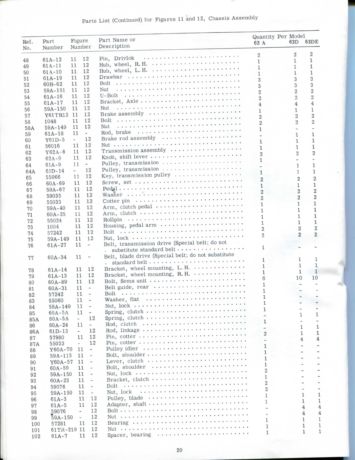
Parts
List(Continued)
for
Figures
11and12,Chassis
Assembly
Ref. Part Figure
No.
Number Number
48
61A-12
11 12
49
61A-11 11 12
50
61A-10
11 12
51
61A-19
11 12
52
60B-62
11 12
53
59A-151 11 12
54
61A-16
11 12
55
61A-17
11 12
56
59A-150
11 12
57
Y61TR13
11 12
58 1048
11 12
58A
59A-149
11 12
59
61A-18
11 -
60
Y61D-5
-12
61
56016
11 12
62 Y62A-8 11 12
63
62A-9 11 12
64
61A-9 11 -
64A
61D-14
-12
65
55066
11 12
66
60A-69
11 12
67
59A-67
11 12
68
59035
11 12
69
55033
11 12
70
59A-40
11 12
71
60A-25
11 12
72
55024
11 12
73 1004
11 12
74 57242
11 12
75
59A-149
11 12
76
61A-27
11 -
77
60A-34
11 -
78
61A-14
11 12
79
61A-13
11 12
80
60A-89
11 12
81 60A-31 11 -
82
57242
11 -
83
55060
11 -
84
59A-149
11 -
85
60A-5A 11 -
85A 60A-5A -12
86
60A-24
11 -
86A
61D-13
-12
87
57980
11 12
87A
55033
-12
88
Y60A-70
11 -
89
59A-115
11 -
90
Y60A-57 11 -
91
60A-59
11 -
92
59A-150
11 -
93 60
A-23 11 -
94
59076
11 -
95
59A-150
11 -
96
61A-3 11 12
97 61A-5 11 12
98
59076
-12
99
59A-150
-12
100
57281
11 12
101
61TR-219
11
12
102 61A-7 11 12
PartName
or
Description
Quantity
Per
Model
63A 63D
63DE
Pin,
Drivlok
Hub,
wheel,
R.H
Hub,
wheel,
L.H
Drawbar
Bolt
Nut
U-Bolt
Bracket,Axle
Nut
Brake
assembly
Bolt
Nut
Rod,brake
Brake
rod
assembly
Nut
Transmission
assembly
Knob,
shiftlever
Pulley,
transmission
Pulley,
transmission
Key,transmissionpulley
Screw,
set
Pec|3,l
Washer
Cotter
pin
Arm,
clutchpedal
Arm,
clutch
RoUpin
Housing,
pedal
arm
Bolt
Nut,
lock
Belt,transmissiondrive
(Special
belt;
donot
.substitutestandardbelt
Belt,bladedrive
(Special
belt;
donot
substitute
.standardbelt
Bracket,wheelmounting,
L.
H.
Bracket,wheelmounting,
R.
H
Bolt,
Sems
unit
Beltguide,rear
Bolt
Washer,flat
Nut,
lock
Spring,
clutch
Spring,
clutch
Rod,clutch
Rod,linkage
Pin,
cotter
Pin,
cotter
Pulleyidler
Bolt,shoulder
Lever,clutch
Bolt,shoulder
Nut,
lock
Bracket,clutch
Bolt
Nut,
lock
Pulley,
blade
Adapter,
shaft
Bolt
Nut
Bearing
Nut
Spacer,
bearing
2
1
1
1
3
3
2
2
4
1
2
2
1
1
1
2
1
1
2
1
2
2
1
1
1
1
2
2
1
1
1
6
1
1
1
1
1
1
2
1
1
1
1
2
1
2
2
1
1
2
1
1
1
3
3
2
2
4
1
2
2
1
1
1
2
1
1
2
1
2
2
1
1
1
1
2
2
1
1
1
10
1
1
4
2
1
1
1
3
3
2
2
4
1
2
2
1
1
1
2
1
1
2
1
2
2
1
1
1
1
2
2
1
1
1
10
20
This manual suits for next models
2
Other Springfield Lawn Mower manuals


