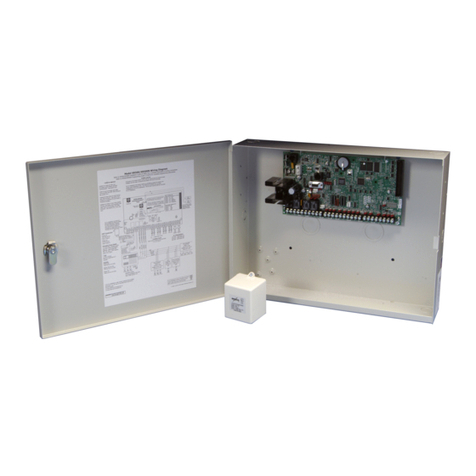
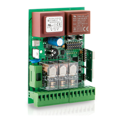
Sprinte ASP 116 evolution User manual

ASP116 EVOLUTION
The Lift control panel
USER MANUAL
FOR ELECTRIC LIFTS
V4.06
01-2012
v5.21
09-2018

USER MANUAL « ASP 116 EVOLUTION »
Sprinte SAS, All rights reserved, including translation rights
2

USER MANUAL « ASP 116 EVOLUTION »
Sprinte SAS, All rights reserved, including translation rights
3
CONTENTS
PRESENTATION ................................................................................................................................................................... 5
1.1 SAFETY INSTRUCTIONS....................................................................................................................................................... 6
1.2 MECHANICAL CHARACTERISTICS .......................................................................................................................................... 6
1.3 ELECTRICAL CHARACTERISTICS............................................................................................................................................. 6
1.4 CONTROL PANEL .............................................................................................................................................................. 7
1.5 WHAT’S NEW SINCE 5-20 SOFTWARE VERSION ...................................................................................................................... 8
1.5.1 New functions ..................................................................................................................................................... 8
1.5.2 Modifications ...................................................................................................................................................... 8
1.5.3 Corrections .......................................................................................................................................................... 9
2SETUP THE LIFT EQUIPMENTS.................................................................................................................................... 10
2.1 MODIFYING A SETTING .................................................................................................................................................... 10
2.2 RELOADING FACTORY SETTINGS......................................................................................................................................... 10
2.3 MYLIFT,APPLICATION FOR SMARTPHONE............................................................................................................................ 11
2.4 SETUP MENU ............................................................................................................................................................. 11
2.5 CONTROL PANEL CHARACTERISTICS .................................................................................................................................... 12
2.6 EQUIPMENT CHARACTERISTICS.......................................................................................................................................... 13
2.7 TEMPERATURE CONTROL ................................................................................................................................................. 15
2.8 POWER SUPPLY.............................................................................................................................................................. 16
2.9 IDENTIFICATION ............................................................................................................................................................. 16
2.10 HOIST MECHANISM ........................................................................................................................................................ 17
2.10.1 Electric lift ......................................................................................................................................................... 17
2.10.2 Standard configuration ..................................................................................................................................... 19
2.11 AUTOMATIC EVACUATION................................................................................................................................................ 19
2.12 FREQUENCY INVERTER SETTINGS........................................................................................................................................ 20
2.12.1 Lift information ................................................................................................................................................. 21
2.12.2 Motor characteristics ........................................................................................................................................ 23
2.12.3 Auto-tuning optimisation.................................................................................................................................. 24
2.12.4 Encoder characteristics ..................................................................................................................................... 25
2.12.5 Speed loop optimisation.................................................................................................................................... 26
2.12.6 RollBack function for synchronous motors........................................................................................................ 26
2.12.7 Brake management........................................................................................................................................... 27
2.12.8 Asynchronous motors optimisation .................................................................................................................. 28
2.12.9 Inspection mode................................................................................................................................................ 29
2.12.10 Electric noise reduction ................................................................................................................................. 29
2.13 BRAKE CONTROL ............................................................................................................................................................ 30
2.14 RE-LEVELLING OPERATION................................................................................................................................................ 31
2.15 BUILDING ..................................................................................................................................................................... 32
2.16 USER OPERATION ........................................................................................................................................................... 34
2.17 FIRE OPERATION ............................................................................................................................................................ 36
2.18 VOICE SYNTHESIS ........................................................................................................................................................... 37
2.18.1 Voice synthesis in car ........................................................................................................................................ 37
2.18.2 Music in the car................................................................................................................................................. 38
2.18.3 Voice synthesis on the car roof.......................................................................................................................... 39
2.18.4 Voice synthesis on floors ................................................................................................................................... 40
2.19 VISUAL INDICATIONS....................................................................................................................................................... 41
2.19.1 Visual indications in car..................................................................................................................................... 41
2.19.2 Visual indications on floors ............................................................................................................................... 43
2.20 DOORS......................................................................................................................................................................... 45
2.21 CAR POSITIONING SYSTEMS .............................................................................................................................................. 49
2.21.1 Configuration of K04SP / K05SP ........................................................................................................................ 50
2.22 CAR LOAD CONTROLS ...................................................................................................................................................... 51

USER MANUAL « ASP 116 EVOLUTION »
Sprinte SAS, All rights reserved, including translation rights
4
2.23 OVERSPEED MONITOR FOR MACHINEROOMLESS LIFTS. .......................................................................................................... 51
2.24 EMERGENCY TELEPHONES ................................................................................................................................................ 52
2.25 ENERGY SAVINGS ........................................................................................................................................................... 52
3CONFIGURATION OF ELECTRONIC BOARDS « INPUTS / OUTPUTS ».......................................................................... 53
3.1 CAR AND FLOORS BUTTONS .............................................................................................................................................. 53
3.1.1 216SP................................................................................................................................................................. 53
3.1.2 217SP................................................................................................................................................................. 53
3.2 CONFIGURATION OF SPECIAL I/O OF 217SP........................................................................................................................ 54
3.3 CONFIGURATION OF FLOOR INDICATION.............................................................................................................................. 54
3.4 CONFIGURATION I/O SUPERVISION.................................................................................................................................... 55
3.5 I/O CONFIGURATION OF THE BUS FLOORS (228SP, 137SP)................................................................................................... 57
4LIFT CONTROLLER MAINTENANCE ............................................................................................................................. 58
4.1 MAKE CALLS WITH THE CONTROLLER .................................................................................................................................. 58
4.2 TECHNICAL ASSISTANCE MENU .......................................................................................................................................... 58
4.3 DIAGNOSIS MENU .......................................................................................................................................................... 60
4.4 FAULTS LIST .................................................................................................................................................................. 61
4.4.1 Power supply ..................................................................................................................................................... 61
4.4.2 Lift ..................................................................................................................................................................... 62
4.4.3 Control panel..................................................................................................................................................... 62
4.4.4 Car boards ......................................................................................................................................................... 64
4.4.5 Floor boards ...................................................................................................................................................... 64
4.4.6 Selection ............................................................................................................................................................ 66
4.4.7 K04SP/K05SP ..................................................................................................................................................... 67
4.4.8 Safety chain....................................................................................................................................................... 67
4.4.9 Levelling ............................................................................................................................................................ 69
4.4.10 Movement......................................................................................................................................................... 70
4.4.11 Doors ................................................................................................................................................................. 73
4.4.12 Overspeed ......................................................................................................................................................... 74
4.4.13 Temperature ..................................................................................................................................................... 74
4.4.14 Inverter.............................................................................................................................................................. 75
5ELECTRONICS BOARDS .............................................................................................................................................. 78
5.1 ELECTRONICS BOARD IN MACHINERY .................................................................................................................................. 78
5.1.1 Lift controller boards « 216SP » ........................................................................................................................ 78
5.1.2 217SP expansion board ..................................................................................................................................... 81
5.1.3 214SP Power supply board................................................................................................................................ 82
5.1.4 220SP motor interface board ............................................................................................................................ 83
5.1.5 225SP Expansion board 2 speeds motor ........................................................................................................... 84
5.1.6 212SP safety chain distribution board.............................................................................................................. 85
5.2 ELECTRONIC CARS IN INSPECTION BOX ................................................................................................................................ 86
5.2.1 211SP car controller board................................................................................................................................ 86
5.2.2 210SP safety chain distribution board .............................................................................................................. 90
5.2.3 222SP power board for door second service ..................................................................................................... 92
5.2.4 223SP extension board for door second service ................................................................................................ 93
5.2.5 230SP Bluetooth board.................................................................................................................................... 94
5.3 LANDING ELECTRONICS BOARDS ........................................................................................................................................ 95
5.3.1 228SP landing board ......................................................................................................................................... 95
5.3.2 137SP landing board with voice synthesizer ..................................................................................................... 96
Document Reference :B-DP-10-006-09

USER MANUAL « ASP 116 EVOLUTION »
Sprinte SAS, All rights reserved, including translation rights
5
Presentation
This manual is the reference document for installation and maintenance of your “ASP 116 evolution” control
panel. It explains in detail the configuration and diagnostic of your control panel.
This new range of control panels designed by Sprinte introduces the latest technology to meet lifts’ new
requirements. The “ASP 116 evolution” control panel is modular and particularly suited to modernising lifts.
Main functionalities:
- 32 floors
- CANopen LIFT compliant
Power control options:
- Variable frequency control 4 kw to 55 kw (Gear and Gearless)
- One or two speed control
- Speed until 1.6 m/s
- Optimization of energy consumption
Car positioning
- Magnetic reader with magnets on guide rails
- Optic fork (224SP)
- Absolute encoder with notched band (K04SP)
- Absolute reader with encoded stainless steel band./
Operation type:
- Universal travel, Up or Down Collective, Full Collective
- Up to quadruplex control
- Fire EN 81-73
- Inspection and emergency operation
- Key “reserved car”
- Overload detection
- Access codes with the car operating panel
- Two car operating panel
Door controls
- 2 doors
- Manual doors
- Fully automatic doors
- VVF doors (Nudging)
- Door open levelling
- Two doors with passing or selective mode
- Automatic and manual landing doors on the same face
Indicators
- Positions indicators (Dot matrix, LCD, TFT colour)
- Direction and next departure arrows
- Voice announcement of floor

USER MANUAL « ASP 116 EVOLUTION »
Sprinte SAS, All rights reserved, including translation rights
6
Main advantages:
- Only one flat cable
- MP3 speech synthesizer
- Security chain pre-wired
- Configuration and application software saved on the SDCard
- 2 lines * 20 characters LCD display
- All defaults saved on the SD-CARD
- Time and date of the faults
- Control of Machine room temperature
- Voice assistance for the technical
1.1 Safety instructions
1) The control panel must be installed in a dry, clean room and only accessible to authorised staff.
2) The room temperature must not exceed 40° and must be greater than 0°
3) The lift must be taken out of service if the two-way communication system is not working
1.2 Mechanical characteristics
Cabinet size:
Power
Operation
4 to 11Kw
15 to 30Kw
37 to 55Kw
Frequency variation
800 x 600 x 300
1200 x 800 x 400
1600 x 900 x 400
Hydraulic control
800 x 600 x 200
800 x 600 x 200
800 x 600 x 200
Electric 1 and 2
speeds
800 x 600 x 200
800 x 600 x 200
800 x 600 x 200
The cabinet size can vary according to options
The control panel weight varies between 25Kg and 100Kg according to power
1.3 Electrical characteristics
The control panels are serial equipped with a protection system against lightning and all the contactors are
installed on Silentblocs in order to reduce noise emission outside thecontrolpanel
Working voltage
220Vac / 230Vac single phase or three phase, 380Vac /
400Vac three phase
Power consumption
70VA no load
Available voltage
24V full-wave 2A, 55V / 70V full-wave 4A, 110Vac / 1A, 220V
“220F” /2A
Safety chain voltage
110VAC
Emergency voltage
Battery 12V / 2,1Ah or 7,1 Ah
Call / Car buttons
Inputs / outputs single wire, earth return, voltage 24V
continuous
Type of indication (LED or light 24V / 50mA max)
This manual describes the functions of the software V04.06. It is possible that older versions of
software do not have all the features described. Check the version of the software before you
start reading the manual.

USER MANUAL « ASP 116 EVOLUTION »
Sprinte SAS, All rights reserved, including translation rights
7
1.4 Control panel
The control panel comprises an alphanumeric screen and navigation keypad equipped with five integrated
buttons. The control panel screen enables the lift’s status to be known at all times. The SDCard contains the lift’s
configuration and the lift’s software to enable restarting under the same conditions if the board is changed.
Contrast adjustment
Press and hold down the “BACK” key and press “+”to increase contrast or “-”to decrease it.
Navigating in the menus
Press the “ENTER” key on the keyboard to go into the lift’s configuration and diagnostics menu. Then press the
““ or ““ keys to navigate in the main menu. Push the “ENTER” key again to go into the desired submenu and
the “BACK” key to come back out of it.
+
Navigating in menu and selecting
the value of a configuration
option
-
Navigating in menu and selecting
the value of a configuration
option
BACK
Navigating in menu and
cancelling a configuration
modification
BAC
K
MODE
IN USE
EMERGENCY OPERA
INSPECTION
OUT OF USE
EMERGENCY
OUT OF POWER
LEVEL
A: AT LEVEL
U: UNDER LEVEL
O: OVER LEVEL
N: BETWEEN LEVELS
CURRENT ACTION
DOOR OPENING
CAR OVERLOAD
PRIORITY
…./…..
VCC
DFT
IN USE A0 D
AVAILABLE
RESET
TER
BACK
ENTER
+
-
ENTER
Pushing the “ENTER”key
enables going back into
configuration and diagnostic
mode
RESET
Pushing this key for 4
seconds causes a control
panel RESET
“D” indicates there are
faults memorised
“D” flashes if a new
fault is recorded

USER MANUAL « ASP 116 EVOLUTION »
Sprinte SAS, All rights reserved, including translation rights
8
1.5 What’s new since 5-20 software version
1.5.1 New functions
K05SP Car positioning system
This new car positioning system K05SP is an absolute linear shaft reader. Position is written on the encoded
stainless steel tape mounted from top to bottom of the shaft
The main assets of this reader :
1 mm precision.
very compact housing.
extremely simple assembly.
Sam shaft’s learning procedure as K04SP.
Very silent even at high speed
The choice of this reader appears in the following menu : CONFIGURATION ►CAR POSITION ►READER
Out of Use operation with doors opened
It’s now possible the car stands still with doors opened while the lift is in Out of Use operation,
It can be chosen in the following menu : CONFIGURATION ►BUILDING ►OOU.DOORS.OPENED
New floors indications selection
With 232 , 236 and 262 displays , the following indications have been added to the list :
0/1 , 1/2, 2/3 , 3/4 , 4/5 , 5/6, 6/7 , an 7/8
It can be chosen in the following menu : CONFIGURATION ►INDICATION ►FLOOR/DISPLAY.
Construction year
This parameter is only for informative purpose and shall be set to the construction year of the lift. This
construction year will be then displayed next to the CE mark on the load plate of the 236SP1 display.
If the year is set to 0, nothing will be displayed.
This setting can be found in the menu : CONFIGURATION ►IDENTIFICATION ►CONSTRUCT. YEAR
New supervision output "CALL °PENDING".
This output is activated as soon as an user request (car call or hall call) is currently pending or in progress ;the
output is reset as soon as there are not any user calls anymore or in case the lift is not in user mode.
It can be chosen in the following menu : CONFIGURATION ►I/O BOARDS ►217SP► I/O REMOTE
Hoistway access detection
The hoistway access detection sets the lift out of order, in the case a landing door has been detected opened for
longer than 8 seconds (thanks to the landing doors safety locking contact), out of a normal car parking in user
mode. The presence of a technician is mandatory to set back the lift in user mode.
This detection only occurs in user mode
Caution : this detection can’t operate properly with a lift compliant to EN81-20 standard , as in that case the
landing doors are always unlocked when the lift is idle in user mode.
This detection can be enabled in the menu CONFIGURATION ►OPERATIONS ►HWAY.ACC.DETECT.
1.5.2 Modifications
Modification of the procedure after pit inspection
The procedure defined in the ASP116 EVOLUTION to put back the lift in service after exiting the pit inspection
mode, has been simplified. It is fully detailed in the installation (ref. B-DP-13-006 Annexe 2-5).
This procedure is valid only if the following parameter :
CONFIGURATION ►EQUIPEMENT ►REARM.INS.CUV. is set to [BY ASP116-EVO] (voir 2.6)
Door Bypass Device activation
The user mode is set of use as soon as the Door Bypass Device is activated .
Music in car
The playback of the music in car is stopped as soon as an emergency phone communication is detected. For
that, the 230SP board is needed, as the yellow/green indicators outputs of the phone are connected on this
board ; and the controller uses its states to detect the use of the emergency phone.

USER MANUAL « ASP 116 EVOLUTION »
Sprinte SAS, All rights reserved, including translation rights
9
1.5.3 Corrections
In some rare cases, the « DIAL 211 BOARD » fault could be indefinetely detected, causing the lift to be
set out of use mode
In preparation for departure, and with the « maitainied closing » parameter set, a door for a service could
be reopened, because the door of the other service was already opened
In case of a software update form a version older than 4-06G to a version 5-12 or more, and with a
K04SP reader, the « DOOR AREA ON » fault was always detetced on the lowest floor.
In universal operation, the car could be « stuck » in preparation for departure » in the case a car call was
done during a levelling operation while the doors were closing.
The message « OCCUPIED » swithced off the 122SP display connected on the 216SP board, now the
display is unchanged.
A shaft light request from the pit inspection switched on the lights of all the shafts of the lift group.
In case of a main power supply failure, and with the « A3 CONTROL » parameter enabled, the « BRAKE
UNRELEASED » fault was always detected.
The max closing timer wasn’t used in case of nudging for the doors.

USER MANUAL « ASP 116 EVOLUTION »
CONFIGURATION
Sprinte SAS, All rights reserved, including translation rights
10
2 Setup the lift equipments
The “SETUP” menu is used to adapt the control panel to your lift. It defines the lift’s system requirements as well
as the settings enabling the installation’s performance to be optimised.
All the control panels are delivered preconfigured according to the client’s datas.
The parameters with a start indication (example: « [PARAM]* ») are the default parameters
2.1 Modifying a setting
Modifying a setting is only authorised if the “PROTEC CONFIG” setting is set to “NOT PROTECTED”. If not a
message “MODIF NOT AUTH.” will appear.
To modify a setting, select it and press the “ENTER” key, the current value starts flashing. Pressing the “”or “”
keys changes its value. To validate your selection press the “ENTER” key again, the new value is saved and does
not flash. To cancel your modification press the “ESC” key.
Takes account of modifications
The modifications are not taking account while the lift is in use.
To save the modifications, press the “BACK” key several time to return to the main menu
The following message appears:
After 2 seconds, you can switch to the standard indication by pressing “BACK” key.
Take account of new settings
Wait until the lift is in an available state, ensure there is no-one remaining inside the car then
press the “RESET” key for two to three seconds. The lift restarts after initialisation with the new
settings.
2.2 Reloading factory settings
The configuration used by the control panel is saved in the DCF.txt file. Each setting modified by the console is
therefore saved in this file. In case of a problem loading the configuration or incorrect operation following a
configuration modification, you can go back to the factory settings. This configuration is backed-up in the EDS.txt
file.
To go back to the factory settings:
1) Press the “+”button and the “- “button
2) Do a reset by keeping the “+”and “-“ buttons pressed down
3) Press the “ENTER“ key.
4) The lift control panel is configured with the factory settings
SAVE?
YES (+) NO (-)
Press “+”to confirm the modification or “-“to cancel
If you pressed “+” the message “MODIFIED CONFIG”appears
FACTORY SETTINGS
CONFIRMATION OK>

USER MANUAL « ASP 116 EVOLUTION »
CONFIGURATION
Sprinte SAS, All rights reserved, including translation rights
11
2.3 MyLift, application for smartphone.
“MyLift” application is a software for android-based devices designed to the lift’s owners and intended
to help them customize their lift this application gives access only to all of the user’s settings of the lift (voice
synthesizer, music, displays, access codes, date & time, etc...). Changes made with this application are taken
instantly in account by the controller, no need to reset it.
This application needs the second 230SP board, to give a separate bluetooth access from the first 230SP.
MyLift is available on
Google PlayStore
Every editable settings with Mylift , are identified
throughout this document by the logo of the application:
2.4 SETUP MENU
CONTROL PANEL
Protection of settings modification, selection of display language on the digital
console, date and time adjustment
EQUIPMENT
Control panel series type, consulting software version, number of expansion
boards
TEMPERATURE
Machinery temperature adjustment detection
POWER SUPPLY
Phase inversion
IDENTIFICATION
Name of client, address of lift, serial number, lift number in multiplex
HOIST
Hoist mechanism : Hydraulic systems, drive systems
RESCUE
Automatic evacuation of passengers in case of main power failure.
FREQ. INVERTER
Configuration of the inverter connected in CANbus with the 216SP controller
BRAKE
Brake configuration
LEVELLING
Levelling of the car with the doors opened
BUILDING
Number of levels, car stop level,..
OPERATIONS
type of operation, car light timer, car priority timer, car priority key
FIRE
Configuration of stricken floors, type of fire operation
VOICE SYNTHESIS
Voice synthesis configuration
INDICATORS
Configuration of type of displays landings and car with configuration of display
at each level. Type of arrow on landing and in car
DOORS
Type of doors, nudging, timers, CPC, SHOCK, opening/closing button, electro
cam, pre-opening.
CAR POSITION
Type of reader, recalibration, close levels, crossed flags
CAR LOAD
Overload ,complete
OVERSPEED
Settings for the overspeed monitor
ALARM
phone alarm configuration
ENERGY SAVINGS
Settings for the energy savings mode of the lift.
BOARDS I/O
Input-output settings for electronic boards of the controller

USER MANUAL « ASP 116 EVOLUTION »
CONFIGURATION
Sprinte SAS, All rights reserved, including translation rights
12
2.5 Control panel characteristics
SETUP ►CONTROL PANEL
SETUP
Protection of settings modification
[PROTECTED]*
Consulting the configuration. No setting can be modified in this mode
[NOT PROTECTED]
Consulting and modifying the configuration
LANGUAGE
Choix de la langue d’affichage sur la console de l’armoire
[FRENCH]* [ENGLISH]
DATE
Date display
Date setting :
Press « ENTER » and press the arrows to change the day, the month and the year.
Press « ENTER » to validate the new date or « ESC » to cancel.
TIME
Time display
Time setting :
Press « ENTER » and press the arrows to change the hour, the minutes and the
second. Press « ENTER » to validate the new time or « ESC » to cancel.
NIGHT START
Display of start time for night schedule
The night range is used to reduce the sound volume of the vocal synthesis during the
night
Adjustment as for TIME setting
NIGHT END
Display of end time for night schedule
Adjustment as for TIME setting

USER MANUAL « ASP 116 EVOLUTION »
CONFIGURATION
Sprinte SAS, All rights reserved, including translation rights
13
2.6 Equipment characteristics
CONFIGURATION ►EQUIPMENT
VERSIONS
Application version and electronic boards version of the equipment
[y.z]
POWER BOARD
Type of power board connected to the 216SP board
[NO BOARD], [220SP], [220SP+225SP]
PIT INSPECT. BOX
Presence of an inspection box in the pit.
If this box is present on your lift, you can plug it on 137SP board connected on the
landing CAN bus, or directly on 216SP main board
Be aware that in case of 137SP ,this board is not to be considered in the « LAND.
BOARDS NB » (see below in this table).
This 137SP board is fixed to ID #27, e.g. DIP1 DIP2 DIP4 and DIP5 set to ON, all
others set to OFF
[NO], [ON CN7/137SP], [ON PE3M/216SP]
PIT INSP.REARM.
Selection of the reset system after exiting pit inspection mode
This reset system may be fulfilled :
either by ASP116 Evolution
(procedure is fully detailed in the installation manual B-DP-13-006 Ann.2-5),
or by an external autonomous device
[BY ASP116-EVO], [BY EXT.SYSTEM]
PIT INSP.VOLUME
Volume adjustement of pit inspection box.
This setting is available only if the pit inspection box is managed by a 137SP board .
[0..7]
DBD
(Door Bypass device)
Presence of Door safety contacts bypass device.
This device is required by EN81-20 standard for maintenance of the doors’ contacts.
[NO], [YES]
217SP BOARDS NB
Number of 217SP boards
[0*..2]
223SP BOARDS NB
Number of 223SP boards
[0*..2]
LAND. BOARDS NB
Number of 228SP and 137SP boards on landing CanBus
[0*..25]
The boards are identified by the JT1 selector of the boards.
The identification is binary code:
DIP 1 = 1 if DIP1 is ON, DIP 2 = 2 if DIP2 is ON, DIP 3 = 4 if DIP3 is ON,
DIP 4 = 8 if DIP4 is ON, DIP 5 = 16 if DIP5 is ON,
Board = V _DIP1 + V_DIP2 * 2 + V_DIP3 * 4 + V_DIP4 * 8 + V_DIP5 * 16
Examples :
Board 0 : All the DIPs OFF
Board 10 : DIPs 2, 4 are ON
Board 23 : DIPs 1, 2, 3, 6 are ON
The “0 board” is the last on the bus (she has a tank circuit). The previous board is
numbered 1 and so on.
1 -2
1 -2
EXT 0
EXT 1

USER MANUAL « ASP 116 EVOLUTION »
CONFIGURATION
Sprinte SAS, All rights reserved, including translation rights
14
230SP BOARDS NB
Number of 230SP boards
This board is used for Bluetooth communication and remote alarm LEDs
[0*..2]
BLUETOOTH PIN
Access code to the gateway 230SP n°0
This code secures bluetooth access to the lift control panel with EvoPAD application.
[XXXX]
CUST.BTOOTH PIN
Access code to the gateway 230SP n°1
This code secures bluetooth access to the lift control panel with the application
dedicated to the final customer (“MyLift” app., ...)
[1234](default value)
MPLEX
Multiplex gateway
Using a gateway between the lift control panels to separate the floors CANbus
This parameter can’t be disabled if there is at least one board connected on the
landing bus (landing panel board ,pit inspection board , flexypage..).
[OUI] * [NON]

USER MANUAL « ASP 116 EVOLUTION »
CONFIGURATION
Sprinte SAS, All rights reserved, including translation rights
15
2.7 Temperature control
SETUP ►TEMPERATURE
Chapter 0.4.16 of the standard EN81-20:2014: To ensure the correct functioning of the equipment in the well
and machinery space(s), i.e. taking into account the heat dissipated by the equipment, the ambient
temperature in the well and the machinery space(s) is assumed to be maintained between +5 °C and +40 °C.
Temperature control in the control panel
This security prohibiting lift operation if the temperature in the control panel exceeds the maximum tolerances
authorised by the electronic components.
MAX PANEL T°
Maximum temperature in control panel
If the temperature exceeds this threshold, the lift makes the passengers exit and
goes out of service until the temperature comes back down below the threshold
[20..70] °C (70°C by default)
MIN PANEL T°
Minimum temperature in control panel
If the temperature goes below this threshold, the lift makes the passengers exit and
goes out of service until the temperature goes back up above the threshold
[-10..15] °C ( 0°C by default)
Temperature control in machine room
Security prohibiting lift operation if the temperature in the machine room exceeds the maximum tolerances
authorised by the standard.
MACHINE ROOM T°
Activation of the temperature controls in the machine room
Le control sis done by a 132SP temperature captor that it is connected to the MC2M
connector of the 216SP board.
[YES]* [NO]
MAX MACHINE T°
Maximum temperature in machine room
If the temperature exceeds this threshold, the lift makes the passengers exit and
goes out of service until the temperature comes back down below the threshold
[20..60] °C (40°C by default)
MIN MACHINE T°
Minimum temperature in machine room
If the temperature exceeds this threshold, the lift makes the passengers exit and
goes out of service until the temperature comes back down below the threshold
[-10..15] °C ( 0°C by default
)
HEATING
Switching on heating if temperature is lower than the threshold
Output CN6I-CHAUF / 220SP is activated
[-10..18] °C ( 5°C by default)
VENTILATION
Switching on ventilation if temperature is greater than threshold
Output CN6I-VENT / 220SP is activated
[22..60] °C ( 30°C by default)

USER MANUAL « ASP 116 EVOLUTION »
CONFIGURATION
Sprinte SAS, All rights reserved, including translation rights
16
2.8 Power supply
SETUP ►POWER SUPPLY
PHASE CONTROL
Detection of phase inversion or failure
[NO DETECTION][DETECTION]*
2.9 Identification
CONFIGURATION ►IDENTIFICATION
CLIENT
Name of client
Name of company
[16 characters]
REFERENCE
Reference name
Lift address where control panel is installed
[16 characters]
SERIAL NUMBER
Control panel serial number
[YYMMXXX] YY : Year of manufacture MM : Month of manufacture
XXX : Number in the month
SIMPLEX NUMBER
Multiplex lift number
[1*..4] In multiplex each lift must have a separate number
LIFT MARK
Serial lift number displayed in car
N° [16 characters]
CE MARK
CE mark displayed in car
[XXXX]
CONSTRUCT.YEAR
Construction year of the lift
This construction year will be displayed next to the CE mark on the load plate of the
236SP1 display.If the year is set to 0, nothing will be displayed.
[XXXX]

USER MANUAL « ASP 116 EVOLUTION »
CONFIGURATION
Sprinte SAS, All rights reserved, including translation rights
17
2.10 Hoist mechanism
SETUP ►HOIST
HOIST TYPE
Type de traction
[ELECTRIC VVF][HYDRAULIC] [ELECTRIC 1V][ELECTRIC 2V]
2.10.1 Electric lift
INVERTER
Type of frequency inverter
[ADL300 M-SPEED][Z.A. ZETADYN][ALTIVAR ATV71L] [ATV71L BUS]
INSPECTION SPEED
Selection of movement speed during inspection
[LOW SPEED]* [HIGH SPEED]
TRACTION TYPE
Traction type
[POSITIV DRV LIFT][FRICTION LIFT] [GEARLESS MOTOR]
RELEASE LINE
Timing delay of the release of line contactors
Adjustment of time limit to release the line contactors , see control timing chart next
page
[0.4..4] seconds (1,5 s by default)
ROPE WEAR
Monitoring of the wear of plastic sheathed ropes
The plastic sheathed ropes have to be replaced after a maximum number of direction
changes of the car (see below to adjust this number).
You have to activate this function if your lift is equipped with these ropes
[NO]* [YES]
MAX NB (ROPE)
Maximum number of direction changes (for rope wear).
Ask the ropes supplier to set the correct value.
Every direction changes of the car is counted to monitor the wear of plastic sheathed
ropes..
Once the maximum value set here is reached, the Lift falls out of order and you have
to replace the ropes. A warning is reported at 95% of this max value (see §4.4.10).
The current value of the counter is visible in the DIAGNOSIS->STATISTICS menu
(cf§4.3). When ropes have been replaced, reset this value to 0.
[0..9.999.999]
Inspection speed must not exceed 0.63 m/sec

USER MANUAL « ASP 116 EVOLUTION »
CONFIGURATION
Sprinte SAS, All rights reserved, including translation rights
18
Inverter command timing diagram
Control panel commands
LA, LB : Line contactors
UC : Up command
DC : Down command
HS : High speed command
LS : Low speed command
BRAKE : The brake is driven by the inverter
Signals controlled by the control panel
MR Motor rotation
CC Contactor control
T1 If CC not active at end of 2 seconds: Contactors sticking fault
T2 If RM not active at end of 4 seconds: RM fault
T3 Adjustable brake spring time, release of LA, LB at end of time
T4 If CC not active at end of 2 seconds: Fault contactors sticking
T5 Brake boost time on starting
High speed
deceleration
stop
LA/ LB
BOOST BRAKE
BRAKE
UC or DC
HS
LS or INSP
MR
CC
T2
T3
T1
T5
T4

USER MANUAL « ASP 116 EVOLUTION »
CONFIGURATION
Sprinte SAS, All rights reserved, including translation rights
19
2.10.2 Standard configuration
NO CAR MOVEMENT
Timing to detect a no movement of the car
Maximum car movement time without having information from position reader. Once
time is passed, the lift is faulty.
This security is deactivated in INSPECTION mode and LEVELLING mode
224SP : [10..20] seconds (20 sec by default)
K04SP/K05SP : [01..05] seconds (5 sec by default)
MAX ACCELER.
maximum authorized acceleration of the car measured by K04SP / K05SP
[0..2,5] m.s2 (2,5 sec by default)
« 0 » value disables the function
MAX LS TIMING
Maximum low speed movement lift in normal service
[10..20] seconds (20 s by default)
THERMAL PROTECT
Type of thermal protection of the traction machine
Use the input CN12I-ST / 220SP
[NO PROBE][RESISTIVE PROBE][DRY CONTACT]*
2.11 Automatic evacuation
CONFIGURATION ►RESCUE (only available with ATV 71L BUS inverter type )
RESCUE
Automatic evacuation of passengers in case of main power failure.
In this case, the ATV71L BUS inverter is able to move the car to the nearest floor,
choosing the easiest direction.
[NO] : Rescue off
[BY RELAY]: Rescue is launched by a timer relay.
RESCUE SPEED
Car speed in evacuation operation
This setting is transmitted to the inverter when moving in evacuation operation.
Unit is in Hertz
[0,1..5,0] hz

USER MANUAL « ASP 116 EVOLUTION »
CONFIGURATION
Sprinte SAS, All rights reserved, including translation rights
20
2.12 Frequency inverter settings
CONFIGURATION ►FREQ. INVERTER
Some information like speed, motor current, output frequency, power supply of the inverter are available in this
menu :
DIAGNOSTIC ► INVERTER
Warning, to modify the parameters of the inverter, it is necessary to have :
PROTECT. MENU VF = NON PROTEGE
MENU VF PROTECT.
Protection du menu variateur
[PROTECTED]*
In this mode, you only can read the inverter configuration. The parameter goes
automatically in PROTECTED mode at midnight to avoid wrong manipulation.
[NO PROTECTED]
Put the parameter to «NO PROTECTED” to be authorized to modified the inverter
parameters
LIFT DATAS
Information of the lift
Press « ENTER » to go in the menu
MOTOR DATAS
characteristics of the motor
Press « ENTER » to go in the menu
ENCODER DATAS
characteristics of the encoder
Press « ENTER » to go in the menu
SPEED LOOP
Speed loop optimisation
Press « ENTER » to go in the menu
ROLLBACK
Rollback management
Press « ENTER » to go in the menu
BRAKE
Adjustment of the starting to stopping of the brake
Press « ENTER » to go in the menu
ASYNC. OPTIMIZ.
Asynchronous motors optimisation
Press « ENTER » to go in the menu
INSPECTION MODE
inspection mode parameters
Press « ENTER » to go in the menu
NOISE LEVEL
Noise reduction
Press « ENTER » to go in the menu
Other manuals for ASP 116 evolution
3
Table of contents
