KitchenAid KESS300B User manual

KITCHENAID
ELECTRONIC
RANGE
CONTROLS
“B” & “D” LINE WALL OVENS
JOB AID
Part No. 4317169

- ii -
OBJECTIVE
The objective of this Job Aid is to allow the experienced appliance techni-
cian to become familiar with the operation of the KitchenAid Electronic Range
Control. This Job Aid follows the instructions contained on the companion
training disk, and is designed as reference material.
WHIRLPOOL CORPORATION assumes no responsibility for any repair
made on our products by anyone other than Authorized Factory Ser-
vice Technicians.
Copyright 1995 Whirlpool Corporation
FORWARD
This Job Aid is a reference guide for the experienced technician. It is not
designed as a replacement to basic training, and does not replace the Ser-
vice Manual or the Use and Care Guide.

- iii -
Table of Contents
KitchenAid Electronic Range Controls—“B” Line Slide-In..................................................... Page 2
KitchenAid Electronic Range Controls—“B” Line Freestanding ........................................... Page 4
KitchenAid Electronic Range Controls—“B” Line Freestanding/Slide-In ............................ Page 6
KitchenAid Electronic Range Controls—“D” Line Wall Ovens .............................................. Page 7
Reading The Graphic Display.................................................................................................. Page 12
KitchenAid Electronic Range Controls—“Easy Convect” .................................................... Page 13
KitchenAid Electronic Range Controls—“Easy Convect (Meats)”...................................... Page 14
KitchenAid Electronic Range Controls—“Sabbath Mode” ................................................... Page 23
KitchenAid Electronic Range Controls—“Clean Mode” .......................................................Page 32

- iv -
— NOTES —

- 1 -
Important Safety Information
This manual is intended for factory-service technicians only. We recommend that customers DO NOT
service their own units, because of the complexity and risk of high-voltage electrical shock.
The following information is used throughout this manual, and should be read carefully.
Information that will help you avoid actions that
could cause product damage (scratches, dents,
etc.) and damage to personal property.
NOTE
Helpful information that explains a more compli-
cated step, prior to carrying it out .
CAUTION
WARNING
Information that alerts you to potentially danger-
ous conditions. These conditions can cause
serious personal injury (burns, fire and electrical
shock, etc.) if the suggested procedures are not
observed.
WARNING
Fire Hazard
Do not obstruct the flow of ventilation air.
Electrical Shock Hazard
It is the customer’s responsibility to:
• Contact a qualified electrical installer.
• Assure that electrical installation is adequate
and in conformance with the National Elec-
trical Code, ANSI/NFPA 70—latest edition*,
and all local codes and ordinances.
Failure to do so could result in fire, electrical
shock, or other personal injury.
Take special care when drilling holes into the
wall for venting or electrical wiring. Electrical
wires may be concealed behind the wall cover-
ing.
Failure to do so could result in fire, electrical
shock, or other personal injury.
* National Fire Protection Association
Batterymarch Park
Quincy, Massachusetts 02269
ASSUMES NO RESPONSI-
BILITY FOR ANY REPAIRS MADE ON OUR PROD-
UCTS BY ANYONE OTHER THAN AUTHORIZED
SM
SERVICE TECHNICIANS.

- 2 -
Installation Layout
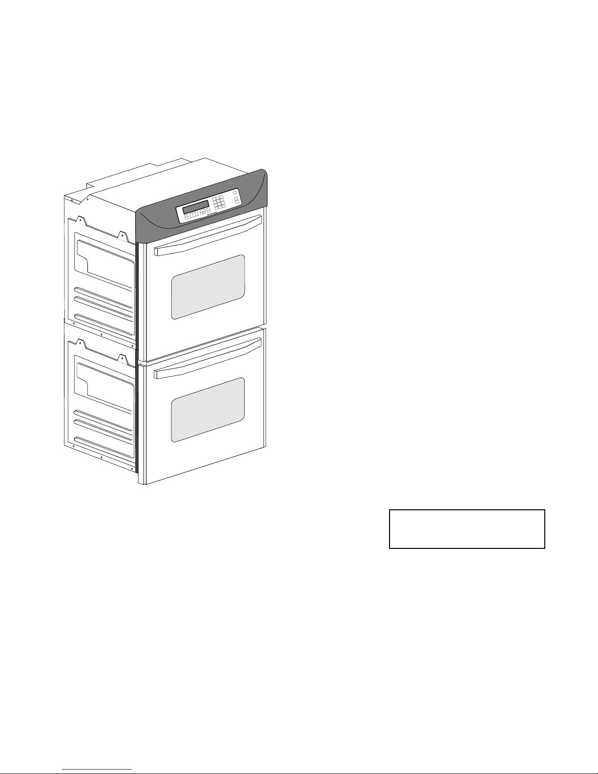
SLIDE-IN ELECTRIC RANGES
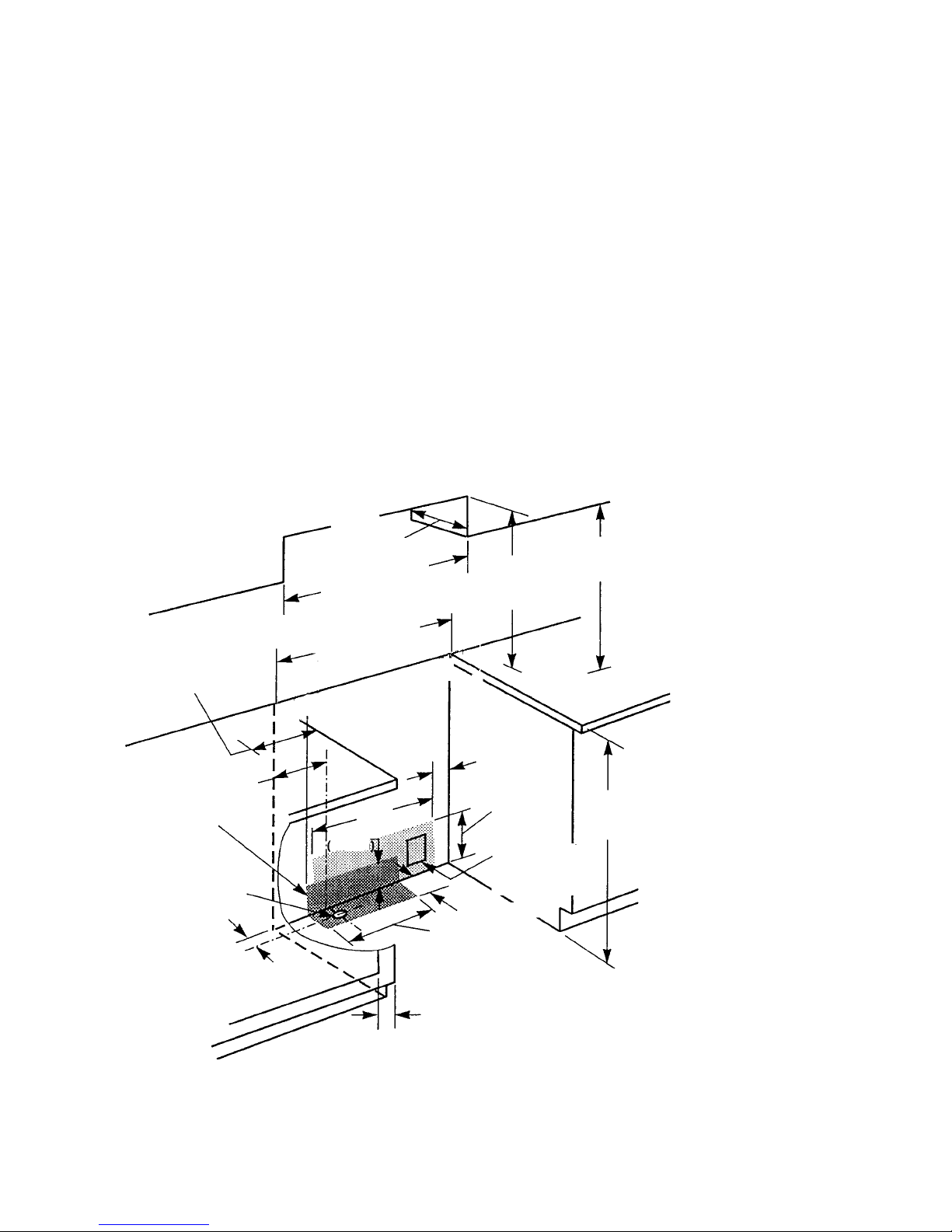
FIGURE 1
Dimensions For Installing The Slide-In
Electric Range
Refer to
“Clearance
Note” above.
13
"
(33 cm)
max. upper
cabinet depth
30
"
(76.2 cm) min.
cabinet opening width
7/8
"
(2.2 cm)
min. required
between cutout
and cabinet door
or hinge.
Wall receptacle is
8" (2-.3 cm) to 22"
(55.9 cm) from
either cabinet.
7" (17.8 cm) max.
from floor.
36
"
(91.4 cm)
countertop
height
4" (10.2 cm) min.
clearance to side
wall or other com-
bustible material on
both sides of the
range.
18
"
(45.7 cm)
upper cabinet to
countertop
30-3/8
"
(77.2 cm) min.
opening width
1/2
"
(1.3 cm)
radius for both
corners 22-3/4
"
(57.8 cm)
opening depth
A grounded electrical outlet is re-
quired for this range.
The Anti-Tip bracket MUST be
installed.
The range should be located away
from strong draft areas, such as
windows, doors, and strong heat-
ing vents or fans. The range should
be located for convenient use in
the kitchen. Recessed installations
must provide complete enclosure
of the sides and rear of the range.
All openings in the wall or floor
where the range is to be installed
must be sealed.
Do not pinch the power cord be-
tween the range and the wall when
you push the range into its mount-
ing location.
The shaded area shown in the il-
lustration is the recommended area
for a 120-VAC outlet on the rear
wall and area for a through-the-
wall connection for gas pipe and
shutoff valve.
than #28 MSG sheet steel, 0.015
"
stainless steel,
0.024
"
aluminum, or 0.020
"
copper. A minimum
clearance of 36
"
(91.4 cm) between the top of the
cooking platform and the bottom of an unprotected
wood or metal cabinet is required.
The cutout shown is for a 25
"
(63.5 cm) countertop
with a 24
"
(61 cm) base cabinet and no backsplash.
The maximum depth for overhead cabinets is 13
"
(33 cm). For the minimum vertical clearance be-
tween the cooking surface and the overhead cabi-
nets, see the previous “Clearance Note.” Over-
head cabinets installed at either side of the range
must be a minimum of 18
"
(45.7 cm) above the
cooking surface. The minimum horizontal distance
between the overhead cabinets is 30
"
(76.2 cm).
Refer to Figure 1 while you read the following
installation information.
Proper installation is your responsibility. A quali-
fied technician must install this range. Make sure
you have everything necessary for correct installa-
tion. It is the responsibility of the installer to comply
with the installation clearances specified on the
serial/rating plate. This plate is located behind the
oven door at the top of the left front frame. IMPOR-
TANT: Be sure to observe all governing codes and
ordinances.
Clearance Note:
A clearance of 30
"
(76.2 cm)
minimum is required when the bottom of a wood or
metal cabinet is protected by not less than 1/4
"
of
flame-retardant millboard covered with not less

- 3 -
FREESTANDING GAS RANGES
This area is
recommended
for 120 VAC outlet
on rear wall
This area is recom-
mended for through-
the-cabinet gas
connection and
shutoff valve
located directly
below the
pressure regulator.
Gas line opening can
be located within this
shaded area.
4" (10.2 cm) min.
clearance to side
wall or other com-
bustible material on
both sides of the
range.
Refer to
“Clearance
Note” above.
18
"
(45.7 cm) min.
clearance upper cabinet
to countertop
18"
(45.7 cm)
2-1/2
"
(6.4 cm)
24"
(64 cm)
2"
(5.1 cm)
7/8
"
(2.2 cm) min. re-
quired between cabinet
opening and door or
hinge opening.
2-1/2
"
6.4 cm
36
"
(91.4 cm)
countertop
height
10"
(25.4 cm)
6"
(15.2 CM)
9"
(22.9 cm)
The Anti-Tip bracket MUST be
installed.
The range should be located away
from strong draft areas, such as
windows, doors, and strong heat-
ing vents or fans. The range should
be located for convenient use in
the kitchen. Recessed installations
must provide complete enclosure
of the sides and rear of the range.
All openings in the wall or floor
where the range is to be installed
must be sealed.
Do not pinch the power cord be-
tween the range and the wall when
you push the range into its mount-
ing location.
The shaded area shown in the il-
lustration is the recommended area
for a 120-VAC outlet on the rear
wall and area for a through-the-
wall connection for gas pipe and
shutoff valve.
A grounded electrical outlet is
required for this range.
FIGURE 2
Dimensions For Installing The
Freestanding Gas Range
Refer to Figure 2 while you read the following
installation information.
Proper installation is your responsibility. A quali-
fied technician must install this range. Make sure
you have everything necessary for correct installa-
tion. It is the responsibility of the installer to comply
with the installation clearances specified on the
serial/rating plate. This plate is located behind the
oven door at the top of the left front frame. IMPOR-
TANT: Be sure to observe all governing codes and
ordinances.
Clearance Note:
A clearance of 30
"
(76.2 cm)
minimum is required when the bottom of a wood or
metal cabinet is protected by not less than 1/4
"
of
flame-retardant millboard covered with not less
than #28 MSG sheet steel, 0.015
"
stainless steel,
0.024
"
aluminum, or 0.020
"
copper. A minimum
clearance of 36
"
(91.4 cm) between the top of the
cooking platform and the bottom of an unprotected
wood or metal cabinet is required.
The cutout shown is for a 25
"
(63.5 cm) countertop
with a 24
"
(61 cm) base cabinet and no backsplash.
The maximum depth for overhead cabinets is 13
"
(33 cm). For the minimum vertical clearance be-
tween the cooking surface and the overhead cabi-
nets, see the previous “Clearance Note.” Over-
head cabinets installed at either side of the range
must be a minimum of 18
"
(45.7 cm) above the
cooking surface. The minimum horizontal distance
between the overhead cabinets is 30
"
(76.2 cm).
13
"
(33 cm)
max.upper
cabinet depth
30
"
(76.2 cm) min.
cabinet opening width
30-3/8
"
(77.2 cm) min.
opening width

- 4 -
Electronic Range Controls
• Used on Gas & Electric Models.
– Slide-In: Up front glass “Capacitive Touch” switch membrane.
– Freestanding: Up front glass “Capacitive Touch” membrane.
• Unique Functions:
– Sabbath Mode: Allows the oven to be operated continuously
during the Jewish Sabbath.
– Easy Convect: Automatically converts standard cooking times
and temperatures to convection cooking times and
temperatures.
– Full Meal Convect: Ten preprogrammed cook cycles and one fa-
vorite cooking cycle.
• 2nd through 5th year parts only warranty on the control.
Slide-In
Freestanding
• Gas Models:
– KGRT500B
– KGRT507B
• Electric Models
(Available in late 1995):
– KERS500B
– KERC500B
– KERC507B
– KERH507B
• Gas Models:
– KGST300B
– KGST307B
• Electric Models:
– KESS300B
– KESC300B
– KESC307B
– KESH307B

- 5 -
Keypads:
1 = Bake
2 = Broil
3 = Clean
4 = Convection Bake
5 = Convection Broil
6 = Convection Roast
7 = Easy Convection (Baked Goods)
8 = Easy Convection (Meats)
9 = Easy Convection (Other Foods)
10 = Cook Time
11 = Stop Time
12 = Convection Full Meal
Electronic Range Controls
Slide-In
Graphic Oven Display
123 10
11
10
11
456
78 9
12 3
#1 #2 #3
#4 #5 #6
#7 #8 #9
#12 #0
OVEN
LIGHT
OVEN
LIGHT
Control
LOCK
SET
START
SET
START
#1 #2 #3
#4 #5 #6
#7 #8 #9
#0
START
START
CANCEL
OFF
CANCEL
OFF
HR MIN MIN SEC
CANCEL
CANCEL
CLOCK
SET - START
CLOCK
SET - START
88: 88
Keypad Layout
Non-Convection Slide-In
Keypad Layout
Convection Slide-In

- 6 -
Keypad Layout
Non-Convection Freestanding
Keypad Layout
Convection Freestanding
Graphic Oven Display
123 10
11
10
11
456
78 9
12 3
#1 #2 #3
#4 #5 #6
#7 #8 #9
#12 #0 OVEN
LIGHT
OVEN
LIGHT
SURFACE
LIGHT
SET
START
NIGHT
SET
START
#1 #2 #3
#4 #5 #6
#7 #8 #9
#0
START
START
CANCEL
OFF
OFF
ON
CANCEL
OFF
HR MIN MIN SEC
CANCEL
CANCEL
CLOCK
SET - START
CLOCK
SET - START
88: 88
SURFACE LIGHT
Keypads:
1 = Bake
2 = Broil
3 = Clean
4 = Convection Bake
5 = Convection Broil
6 = Convection Roast
7 = Easy Convection (Baked Goods)
8 = Easy Convection (Meats)
9 = Easy Convection (Other Foods)
10 = Cook Time
11 = Stop Time
12 = Convection Full Meal
Electronic Range Controls
Freestanding

- 7 -
Electronic Range Controls
The Graphic Display
8:88
8:88
18:88
18:88
88:88
888
ON
HR MIN MIN SEC
TEMP PROBE TIMED DELAY
CONTROL
DOOR LOCKED
START ?
FCOOK TIMER
STOP
CLEAN
ON
RAISING
BREAD
DEHYDRATE CONVECTION
ENTER STANDARD COOK TIME
COOK TEMP CLEAN TIME
SET PROBE TEMP
NIGHT LIGHT DELAY
EASYCONVECT
CLOSE CONTROL LOCK
DOOR LOCKED START ?
START
TIME
STOP
TIME
CHECK
FOOD AT
F
CONVECTION MODELS
NONCONVECTION MODELS
NOTE: Ring element used on electric models only.

- 8 -
Electronic Range Controls
Reading The Graphic Display
8:88
18:88
18:88
888
ON
RAISING
BREAD
DEHYDRATE CONVECTION
ENTER STANDARD COOK TIME
COOK TEMP CLEAN TIME
SET PROBE TEMP
NIGHT LIGHT DELAY
EASYCONVECT
CLOSE CONTROL LOCK
DOOR LOCKED START ?
START
TIME
STOP
TIME
CHECK
FOOD AT
F
Broiler Heat Indicator
Meat Probe Indicator
Time Savings Bar Indicates:
% Of Time Remaining In Cook Cycle
OR
% Of Time Saved With EasyConvect
Ring Element
Electric Convection Only
Bake Heat Indicator

- 9 -
•Available on convection models only.
•Allows the consumer to cook standard oven recipes in
the convection mode.
•Three Easy Convect cooking functions:
–Baked Goods: Converts temperature by –50˚F.
–Meats: Converts time by –20% and temperature by –25˚F.
–Other: Converts time by –10% and temperature by –25˚F.
Electronic Range Controls
Easy Convect™
8:88
18:88
18:88
ON
RAISING
BREAD
DEHYDRATE CONVECTION
ENTER STANDARD COOK TIME
COOK TEMP CLEAN TIME
SET PROBE TEMP
NIGHT LIGHT DELAY
EASYCONVECT
CLOSE CONTROL LOCK
DOOR LOCKED START ?
START
TIME
STOP
TIME
CHECK
FOOD AT
F
#1 #2 #3
#4 #5 #6
#7 #8 #9
#12
Meats
#0
OVEN
LIGHT
START
CANCEL
OFF
Press the “Meats”keypad.
Time of Day
NOTE:
Ring element used
on electric models
only.
CONVECTION MODELS
Easy Convect (Meats)

- 10 -
Electronic Range Controls
Easy Convect (Meats)
18:88
18:88
ON
RAISING
BREAD
DEHYDRATE CONVECTION
ENTER STANDARD COOK TIME
COOK TEMP CLEAN TIME
SET PROBE TEMP
NIGHT LIGHT DELAY
EASYCONVECT
CLOSE CONTROL LOCK
DOOR LOCKED START ?
START
TIME
STOP
TIME
CHECK
FOOD AT
F
#1 #2 #3
#4 #5 #6
#7 #8 #9
#12 #0
OVEN
LIGHT
START
CANCEL
OFF
325
Time of Day
NOTE:
Ring element used
on electric models
only.
CONVECTION MODELS
Enter the normal cooking temperature.
18:88
18:88
ON
RAISING
BREAD
DEHYDRATE CONVECTION
ENTER STANDARD COOK TIME
COOK TEMP CLEAN TIME
SET PROBE TEMP
NIGHT LIGHT DELAY
EASYCONVECT
CLOSE CONTROL LOCK
DOOR LOCKED START ?
START
TIME
STOP
TIME
CHECK
FOOD AT
F
#1 #2 #3
#4 #5 #6
#7 #8 #9
#12 #0 OVEN
LIGHT
START
CANCEL
OFF
325
NOTE:
Ring element used
on electric models
only.
CONVECTION MODELS
Enter the normal cooking time.
Time of Day

- 11 -
Electronic Range Controls
Easy Convect (Meats)
1:00
1:48
ON
RAISING
BREAD
DEHYDRATE CONVECTION
ENTER STANDARD COOK TIME
COOK TEMP CLEAN TIME
SET PROBE TEMP
NIGHT LIGHT DELAY
EASYCONVECT
CLOSE CONTROL LOCK
DOOR LOCKED START ?
START
TIME
STOP
TIME
CHECK
FOOD AT
F
#1 #2 #3
#4 #5 #6
#7 #8 #9
#12 #0
OVEN
LIGHT
START
CANCEL
OFF
300 48
NOTE:
Ring element used
on electric models
only.
CONVECTION MODELS
Press “Start”
After the Start button is pressed, the control
adjusts the convection cooking time by 20%
and the temperature by 25-degrees.
Temperature adjusted by 25˚Convection Cooking Time adjusted by 20%

- 12 -
Electronic Range Controls
Sabbath Mode
•Allows the consumer to meet the “No Work”requirements
of the Jewish Sabbath. This means that:
–The range will operate nonstop as long as power is applied to
the range bypassing the 12-hour shutdown default.
–The range will resume cooking if there is a power failure while in
this mode of operation (convection models will resume the “Fa-
vorite Cycle”).
•No tones will sound when in this mode.
•Touchpad responses are delayed by 1-second to prevent
accidentally turning the range off.
8:88
18:88
18:88
ON
RAISING
BREAD
DEHYDRATE CONVECTION
ENTER STANDARD COOK TIME
COOK TEMP CLEAN TIME
SET PROBE TEMP
NIGHT LIGHT DELAY
EASYCONVECT
CLOSE CONTROL LOCK
DOOR LOCKED START ?
START
TIME
STOP
TIME
CHECK
FOOD AT
F
#1 #2 #3
#4 #5 #6
#7 #8 #9
#12 #0 OVEN
LIGHT
START
CANCEL
OFF
Bake
350
NOTE:
Ring element used
on electric models
only.
Use the Sabbath mode with
the BAKE function only

- 13 -
Electronic Range Controls
Sabbath Mode
8:88
3 7 5
18:88
18:88
ON
RAISING
BREAD
DEHYDRATE CONVECTION
ENTER STANDARD COOK TIME
COOK TEMP CLEAN TIME
SET PROBE TEMP
NIGHT LIGHT DELAY
EASYCONVECT
CLOSE CONTROL LOCK
DOOR LOCKED START ?
START
TIME
STOP
TIME
CHECK
FOOD AT
F
#1 #2 #3
#4 #5 #6
#7 #8 #9
#12 #0
OVEN
LIGHT
START
CANCEL
OFF
Time of Day
NOTE:
Ring element used
on electric models
only.
Set the temperature you desire to use during the Sabbath
Mode. We will use 375˚.
CONVECTION MODELS
8:88
3 7 5
18:88
18:88
ON
RAISING
BREAD
DEHYDRATE CONVECTION
ENTER STANDARD COOK TIME
COOK TEMP CLEAN TIME
SET PROBE TEMP
NIGHT LIGHT DELAY
EASYCONVECT
CLOSE CONTROL LOCK
DOOR LOCKED START ?
START
TIME
STOP
TIME
CHECK
FOOD AT
F
#1 #2 #3
#4 #5 #6
#7 #8 #9
#12 #0 OVEN
LIGHT
START
CANCEL
OFF
Time of Day
Select “Start”and the oven will preheat.
NOTE:
Ring element used
on electric models
only.
CONVECTION MODELS

- 14 -
Electronic Range Controls
Sabbath Mode
8:88
3 7 5
18:88
18:88
ON
RAISING
BREAD
DEHYDRATE CONVECTION
ENTER STANDARD COOK TIME
COOK TEMP CLEAN TIME
SET PROBE TEMP
NIGHT LIGHT DELAY
EASYCONVECT
CLOSE CONTROL LOCK
DOOR LOCKED START ?
START
TIME
STOP
TIME
CHECK
FOOD AT
F
#1 #2 #3
#4 #5 #6
#7 #8 #9
#12 #0
OVEN
LIGHT
START
CANCEL
OFF
Time of Day
NOTE:
Ring element used
on electric models
only.
CONVECTION MODELS
•The Time of Day display changes to “SAbb.”
•When the oven has finished preheating, press and hold
the #6 keypad for 5-seconds.
•The Sabbath Mode can only be cancelled by pressing and
holding the #6 keypad.

- 15 -
Electronic Range Controls
Clean Mode
ON
RAISING
BREAD
DEHYDRATE CONVECTION
ENTER STANDARD COOK TIME
COOK TEMP CLEAN TIME
SET PROBE TEMP
NIGHT LIGHT DELAY
EASYCONVECT
START
TIME
STOP
TIME
CHECK
FOOD AT
F
#1 #2 #3
#4 #5 #6
#7 #8 #9
#12 #0
OVEN
LIGHT
START
CANCEL
OFF
Clean
3:30
4:30
8:00
CLOSE CONTROL LOCK
DOOR LOCKED START ?
The customer selects the “Clean Mode”on the touch panel.
The 3-1/2hour default clean time will be displayed (the cus-
tomer can select a clean cycle of between 2-1/2and 4-1/2hours).
The Start and Stop times will be displayed (based on the time
selected by the customer).

- 16 -
Electronic Range Controls
Clean Mode
At the instant of start:
•The door will lock.
•The Broil Ignitor is ON.
•The Broil Valve is ON.
•The oven will start heating.
3:30
4:30
8:00
ON
RAISING
BREAD
DEHYDRATE CONVECTION
ENTER STANDARD COOK TIME
COOK TEMP CLEAN TIME
SET PROBE TEMP
NIGHT LIGHT DELAY
EASYCONVECT
CLOSE CONTROL LOCK
DOOR LOCKED START ?
START
TIME
STOP
TIME
CHECK
FOOD AT
F
#1 #2 #3
#4 #5 #6
#7 #8 #9
#12 #0
OVEN
LIGHT
START
CANCEL
OFF
12 1
2
3
4
5
6
7
8
9
10
11
N
L1
Broil
Ignitor
Broil
Valve
Bake
Ignitor
Bake
Valve
P6
P11
Clean
Other manuals for KESS300B
1
This manual suits for next models
11
Table of contents
Popular Control Panel manuals by other brands

Matrix Switch Corporation
Matrix Switch Corporation MSC-CP8X4E product manual

SILENTRON
SILENTRON 5500 Silenya HT GSM Top instruction manual

SEA
SEA SETRONIK 1 Restyling user manual

HEIDENHAIN
HEIDENHAIN ITNC 530 - CONVERSATIONAL PROGRAMMING user manual

BFT
BFT ZARA BTL2 installation manual

Eltek
Eltek Delta OP user guide

Notifier
Notifier AFP-3030 Operation manual

Digitus
Digitus DA-90392 Installation instructions & user guide

Ferroli
Ferroli 0Q2K10XA Installation and assembly instructions

Data Aire
Data Aire dara-4g2 Installation, operation & maintenance manual

Viking
Viking B-1 Technical data

weintek
weintek cMT3090 Series Installation instruction