manuals.online logo
Brands
  1. Home
  2. •
  3. Brands
  4. •
  5. Honeywell
  6. •
  7. Control Panel
  8. •
  9. Honeywell NFS-3030 Installation and operating instructions

Honeywell NFS-3030 Installation and operating instructions

NFS-3030
and
NFS-640
Fire Alarm Control Panels
Canadian Addendum
Document 52196ADD
9/20/2003 Rev:A
PN 52196ADD:A ECN 03-419
www.PDF-Zoo.com
Audio Isolator Modules
2Addendum, Canadian Applications PN 52196ADD:A 9/20/2003
Audio Isolator Modules
Description of Modules
The audio isolator modules described below may be used to isolate short circuits during alarm
signaling. These modules are listed with ULC for use with the NFS-3030 and NFS-640.
AIM-1 - This module provides isolation to a separate circuit on an audio riser. A short circuit on an
AIM-1 NAC or speaker circuit will not disable other NACs or speaker circuits on the riser.
RSM-1 - This module works the same as the AIM-1, with the exception that there is a silence button for
in-suite operation. The silence button will silence the audible signal to the module’s circuit for
ten minutes during alarm. Resounding will occur automatically after ten minutes. To override
the ten minute silence, CBE programming must be done at the FACP so that when an AMG-1
is used for paging it interrupts the module’s 24VDC power for two seconds.
Main Power Supply Current Draw
The following table is an addition to the System Draw Current Calculations Table in this panel’s
installation manual. The figures should be used in calculating the current for the main power supply.
Panel Programming
SLC control modules used in conjunction with audio isolator modules must be programmed with one of
the two software Type Codes below.
To override the local ten-minute signal silence initiated by pressing the silence button on an isolator
module, the panel must be programmed to interrupt the module’s 24VDC power (RSM-1) for two
seconds when an AMG-1 is used for paging. This does not affect operation.
Applications
The following figures illustrate typical applications for audio isolator modules. Jumper settings are
specified in Figure 1 below to differentiate between NACs and speaker circuits. Jumpers are located on
the back side of each module.
Figure 1 Jumper Settings
Category
Calculation Column 1
Primary, Non-Fire Alarm
Current (amps)
Calculation Column 2
Primary, Fire Alarm
Current (amps)
Calculation Column 3
Secondary, Non-Fire Alarm
Current (amps)
Qty X [current draw]= Total Qty X [current draw]= Total Qty X [current draw]= Total
RSM-1, AIM-1 [ ] x [0.0145]= [ ] x [0.0145]= [ ] x [0.0145]=
Type Code Silenceable
(Y/N) Configuration Device Function
ISOLATED NAC Y NAC Supervised NAC for notification appliance, used with audio
isolators. Activates even if there is a short on its NAC circuit.
ISOLATED SPK Y NAC Supervised NAC for speaker circuits, used with audio
isolators. Activates even if there is a short on its audio circuit.
AIM-1
Remove jumpers 1 & 2
for speaker applications.
RSM-1
Remove jumpers 1 & 2
for speaker applications.
Jumper 3
AIM-1 RSM-1
Voice-AIM-1back.cdr
Voice-RSM-1back.cdr
www.PDF-Zoo.com
Audio Isolator Modules
Addendum, Canadian Applications PN 52196ADD:A 9/20/2003 3
Figure 2 RSM-1/AIM-1 NAC Connections, Unsupervised, Style Y (Class B)
Figure 3 RSM-1/AIM-1 NAC Connections, Supervised, Style Z (Class A)
90
81
72
63
54
-
-+
+
90
81
72
63
54
+
+
+
+
+
---
-
-
Voice-RSM-1-Ynac.cdr
SLC to next device (Twisted-pair wiring; see
your control panel manual to determine
whether shielding is recommended.) SLC from control panel
or previous device
(Twisted-pair wiring;
see your control panel
manual to determine
whether shielding is
recommended.)
RSM-1 or AIM-1
24VDC power to end-of-
line resistor or next device
Signaling Devices
150 mA Max
FCM-1
or to NFS-640 NAC
to NAC, 24V OUT from listed
fire panel/power supply
RSM-1
Faceplate
RSM-1
Silence
Button
to supervision relay
or next device
90
81
72
63
54
-
-+
+
90
81
72
63
54
+
+
+
+
+
+
+
---
-
-
-
-
Voice-RSM-1-Znac.cdr
SLC to next device (Twisted-pair
wiring; see your control panel
manual to determine whether
shielding is recommended.)
SLC from control panel
or previous device
(Twisted-pair wiring;
see your control panel
manual to determine
whether shielding is
recommended.)
24VDC power to end-
of-line resistor or next
device
Signaling Devices
150 mA Max
RSM-1or AIM-1
FCM-1
or to NFS-640 NAC To supervision
relay or next device
to NAC, 24V OUT from listed
fire panel/power supply
www.PDF-Zoo.com
Audio Isolator Modules
4Addendum, Canadian Applications PN 52196ADD:A 9/20/2003
Figure 4 RSM-1/AIM-1 Speaker Circuit Connections, Unsupervised, Style Y (Class B)
Figure 5 RSM-1/AIM-1 Speaker Circuit Connections, Supervised, Style Z (Class A)
90
81
72
63
54
-
-+
+
90
81
72
63
54
+
+
+
+
+
+
+
+
-
--
-
-
-
-
-
Voice-RSM-1-Yspkr.cdr
SLC to next device (Twisted-
pair wiring; see your control
panel manual to determine
whether shielding is
recommended.)
To next control module (last
device returns to amplifier
for supervision)
Audio Branch Circuit
SLC from control
panel or previous
device
(Twisted-pair wiring;
see your control
panel manual to
determine whether
shielding is
recommended.)
Speaker Circuit to
another device or end-
of-line resistor.
24VDC
power to
end-of-line
resistor or
next device
AA-100
AA-120
Signaling Devices
3.75W Max
RSM-1 or AIM-1
FCM-1
To switched
24VDC
power
24VDC to be applied only in alarm state.
RSM-1 only - the 24VDC power must be
interrupted for 2 seconds to override the
silence button. See the RSM-1 paragraph
under the heading "Description of Modules"
on page 2 of this addendum.
*
*
90
81
72
63
54
-
-+
+
90
81
72
63
54
+
+
+
+
+
+
+
+
+
+
-
-
-
--
-
-
-
-
-
Voice-RSM-1-Zspkr.cdr
SLC to next device (Twisted-pair
wiring; see your control panel
manual to determine whether
shielding is recommended.)
To next control
module (last device
returns to amplifier
for supervision)
Audio Branch Circuit
SLC from control
panel or previous
device
(Twisted-pair wiring;
see your control
panel manual to
determine whether
shielding is
recommended.)
FCM-1
24VDC
power to
end-of-line
resistor or
next device
Speaker Circuit
to another
device or end-of-
line resistor.
AA-100
AA-120
Signaling Devices
3.75W Max
RSM-1 or AIM-1
To switched
24VDC
power
24VDC to be applied only in alarm state.
RSM-1 only - the 24VDC power must be
interrupted for 2 seconds to override the
silence button. See the RSM-1 paragraph
under the heading "Description of Modules"
on page 2 of this addendum.
*
*
www.PDF-Zoo.com

Other manuals for NFS-3030

1

This manual suits for next models

1

Other Honeywell Control Panel manuals

Honeywell Galaxy 2-44+ User manual

Honeywell

Honeywell Galaxy 2-44+ User manual

Honeywell NOTIFIER ID2000 Series Guide

Honeywell

Honeywell NOTIFIER ID2000 Series Guide

Honeywell NOTIFIER SFP-5UD Series User manual

Honeywell

Honeywell NOTIFIER SFP-5UD Series User manual

Honeywell NOTIFIER NFW-50X User manual

Honeywell

Honeywell NOTIFIER NFW-50X User manual

Honeywell FCI Gamewell Flex 404 User manual

Honeywell

Honeywell FCI Gamewell Flex 404 User manual

Honeywell Accenta User manual

Honeywell

Honeywell Accenta User manual

Honeywell TrueZONE HZ221 User manual

Honeywell

Honeywell TrueZONE HZ221 User manual

Honeywell Fire-Lite Alarms MS-9600LS User manual

Honeywell

Honeywell Fire-Lite Alarms MS-9600LS User manual

Honeywell Notifier ID50 Instruction sheet

Honeywell

Honeywell Notifier ID50 Instruction sheet

Honeywell nfs2-3030 User manual

Honeywell

Honeywell nfs2-3030 User manual

Honeywell Gamewell Flex 402 User manual

Honeywell

Honeywell Gamewell Flex 402 User manual

Honeywell Galaxy Dimension series Quick setup guide

Honeywell

Honeywell Galaxy Dimension series Quick setup guide

Honeywell Domonial CMI 800++ User guide

Honeywell

Honeywell Domonial CMI 800++ User guide

Honeywell Tuxedo Touch Wi-Fi Assembly instructions

Honeywell

Honeywell Tuxedo Touch Wi-Fi Assembly instructions

Honeywell Fire-Lite MS-5UD-3 User manual

Honeywell

Honeywell Fire-Lite MS-5UD-3 User manual

Honeywell NOTIFIER AM1000 User manual

Honeywell

Honeywell NOTIFIER AM1000 User manual

Honeywell NOTIFIER INSPIRE E10 User manual

Honeywell

Honeywell NOTIFIER INSPIRE E10 User manual

Honeywell RS-232 User manual

Honeywell

Honeywell RS-232 User manual

Honeywell Fire-Lite Alarms ES-50X User manual

Honeywell

Honeywell Fire-Lite Alarms ES-50X User manual

Honeywell Notifier SFP-2402 User manual

Honeywell

Honeywell Notifier SFP-2402 User manual

Honeywell Notifier AFP-3030 User manual

Honeywell

Honeywell Notifier AFP-3030 User manual

Honeywell T631A-C FARM-O-Stat User manual

Honeywell

Honeywell T631A-C FARM-O-Stat User manual

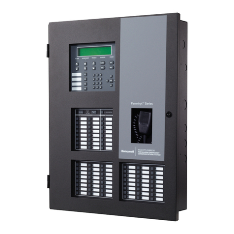
Honeywell Farenhyt Series Technical manual

Honeywell

Honeywell Farenhyt Series Technical manual

Honeywell MS-10UD Series User manual

Honeywell

Honeywell MS-10UD Series User manual

Popular Control Panel manuals by other brands

Black Box C6AMP70-24 manual

Black Box

Black Box C6AMP70-24 manual

Fire Pro FP-22408 Operation and maintenance manual

Fire Pro

Fire Pro FP-22408 Operation and maintenance manual

Fortel DTV Integrity RCP-502 user manual

Fortel DTV

Fortel DTV Integrity RCP-502 user manual

KEBCO HSP5/485 instruction manual

KEBCO

KEBCO HSP5/485 instruction manual

Fire Pro FPC-2 quick start guide

Fire Pro

Fire Pro FPC-2 quick start guide

Ambirad SmartCom3 manual

Ambirad

Ambirad SmartCom3 manual

Fire Pro Sigma XT Procedure

Fire Pro

Fire Pro Sigma XT Procedure

Delta VTH5422HW user manual

Delta

Delta VTH5422HW user manual

Paradox DIGIPLEX DGP-NE96 Reference and installation manual

Paradox

Paradox DIGIPLEX DGP-NE96 Reference and installation manual

Delta DOP-100 Series instruction sheet

Delta

Delta DOP-100 Series instruction sheet

Fire-Lite MS-2410BC Programming, installation, maintenance  and operating instruction manual

Fire-Lite

Fire-Lite MS-2410BC Programming, installation, maintenance and operating instruction manual

TTL UBT plus user manual

TTL

TTL UBT plus user manual

Carel humiFog user manual

Carel

Carel humiFog user manual

Vimar Elvox RS17.P Installer quick guide

Vimar

Vimar Elvox RS17.P Installer quick guide

DEGA DEGA UDA III user manual

DEGA

DEGA DEGA UDA III user manual

DAB E-BOX 2G M Instruction for installation and maintenance

DAB

DAB E-BOX 2G M Instruction for installation and maintenance

Satel PERFECTA Quick user manual

Satel

Satel PERFECTA Quick user manual

Cooper CF3000 user manual

Cooper

Cooper CF3000 user manual

manuals.online logo
manuals.online logoBrands
  • About & Mission
  • Contact us
  • Privacy Policy
  • Terms and Conditions

Copyright 2025 Manuals.Online. All Rights Reserved.