SPT SPARCIN 4000 User manual

1
MANUAL
SPARCIN 4000
STATE OF THE ARC PLASMA CUTTING TECHNOLOGY
Telephone
Email
SPT Plasmateknik AB
Transportvägen 12
SE-241 38 Eslöv
Sweden
Internet
+46 10-172 73 50
www.spt.se
Rev. 1.2, 2011-09-08

2
CONTENTS
1. TECHNICAL DATA 3
2. INSTALLATION 4
3. OPERATION 7
4. STARTUP 15
5. MAINTENANCE 16
6. TROUBLE SHOOTING 17
7. SAFETY INSTRUCTIONS 18
8. WARRANTY 22
9. TORCH 23
10. OPTIMISING THE CUTTING 28
11. CUTTING DATA 31
12. DIAGRAMS 47
13. PARTS LISTS 50

3
1. TECHNICAL DATA
SPARCIN 4000
Mains voltage: 3~50Hz, 400V
Fuse: 80A slow blow
Process power: 20-200A/180V
Duty cycle: 100 %
Maximum power: 40 kVA
Power factor: 0,95
Open circuit voltage: 250V
Dimensions
Power Source (PA): 740 x 510 x 1210 mm
Gas console (GCU): 450 x 420 x 320 mm
Weight: 150 kg

4
2. INSTALLATION
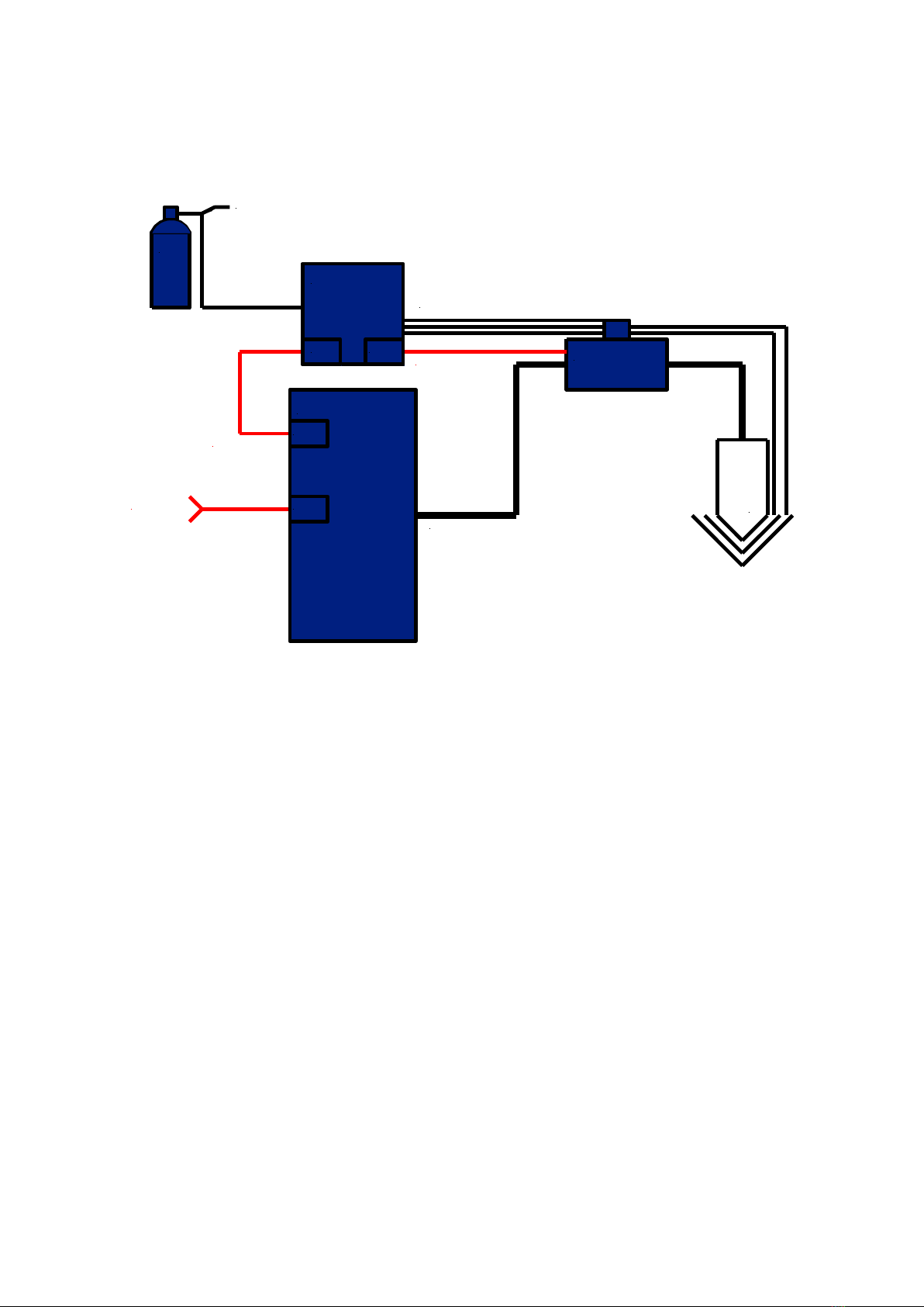
Below is a scheme over the principle of the system and its components. These instructions are
aimed at system builders with experience in mechanised plasma cutting. If such competence
is not available it is advised that SPT be contacted for guidance.
To obtain satisfactory cutting quality and economy it is vital that the CNC-machine be
equipped with a suitable height control device for plasma cutting. The plasma technology
requires a very well defined process control. The height control must be able to handle
different heights for ignition, piercing and cutting. Most robots can easily be programmed to
handle the process.
If a suitable height control system is not available one can be delivered by SPT. Contact us for
advice.
Electrical supply:
SPARCIN 4000: 3~50 Hz, 400V, 80A slow blow
Note that the SPARCIN 4000 is an inverter power source and it requires a stable power
supply. Make sure that the power supply is stable and within 400 V +6/-10 %. A circuit
breaker should be present at the wall socket.
Gas supply:
Connect the gases to the rear of the gas console. Use only 2-step pressure regulators of high
quality and adjust to 9-10 bar on each bottle. Also the compressed air shall be adjusted to 9-10
bar. The compressed air should be dry, oil free and free from particles.
Bear in mind that pressurized oxygen and oil is an explosive combination that can lead to loss
of life as well as destruction of property.
Remote control from robot or CNC
The plasma system is controlled via a multi-pole connector marked “CNC” on the rear panel
of the power source. This should be connected according to diagram further back in this
manual. The system is highly sensitive and it is therefore vital to connect it properly. Pins in
the connector that are not used by the remote control must be left unconnected. If they are
connected to a wire that is left unconnected in the other end this works as an antennae and this
will lead to unwanted behavior.
In some cases it may be necessary to screen the cables.
Safety
Only specially trained personnel should install the SPARCIN 4000 system. National law and
regulations must be followed. Note that parts of the system are electrically live when
connected even though the main power switch is off.

5
System principle
GCU
SPARCIN
Air
Oxygen
Nitrogen
F5
AH35
Gas
TCU
GCUCable
Hose parcel
TCUCable
TORCH
Gas Hoses
CNC
Interface
GCU/AD5
CNC/AD4
PA/AD2 TCU/AD3
Connecting the system
Note! Do not connect electricity until the very last. Parts of the system are live even if the
power switch is off!
Mount the torch connection unit TCU on an appropriate place on the robot or torch
carriage. Make sure that the torch can move without stretching or excessively bending
the hose assembly.
Mount the torch in a suitable holder on the robot or torch carriage. Make sure that the
torch head is easily accessible for replacement and that the holder is electrically
isolated from the torch. Connect the torch to the TCU. Check that the hoses are not
stretched or bent.
Connect the 25 pole control cable marked GCU-PA between the GCU contact on the
plasma power source and the contact marked Power Source or PA on the GCU.
Connect the 9-pole control cable marked GCU-TCU between the GCU and the TCU.
Mount the hose assembly TCL between the power source and the TCU. Make sure
that the hoses are not stretched, bent or twisted as this can lead to excessive wear on
the hoses and also block the coolant flow. The TCL should be drawn via the opening
in the front panel. The connection can be made by opening the side door on the right
hand side of the machine. Open the lid on the TCU and connect the cables and hoses.
Make sure that the ground cable is properly fastened.
Mount the gas hoses 1,2 and 3 between the GCU and the TCU. Be careful to avoid dirt
from entering the hoses. Make sure that there are no creases on the hoses.

6
Connect the hoses from the pressure regulators on the gas bottles to the gas console.
Make sure that explosion protectors are mounted on the regulators connected to
flammable gas and oxygen. Check that the installation is in accordance with
national/regional laws and regulations. Make sure that the different gases are
connected to the right input on the GCU.
If necessary, fill up with coolant. Only use pure mono-ethylene as anti freeze agent
and de-ionised or distilled water. Any other coolant may be electrically conductive
which leads to ignition problems. The original coolant consists of 30% glycol and
70% distilled water which gives freeze protection down to -5°C.
Connect the the power source to the CNC-control system or robot via the 25-pole
contact marked CNC on the rear of the power source. Be very careful to follow the
instruction in the diagram as a faulty connection can lead to disturbance in the
function of the plasma system.
Make sure that all system components and hose assembly screens are grounded
together and that all doors and panels are closed.
Connect gas and make sure that all hoses and connections are tight. Be extra careful
with flammable gases and oxygen. Remember that a gas leak can lead to fire or
explosion with injury to person and property.
Connect the return lead to the front panel of the power source and attach the clamp
directly to the work piece.
The machine is now ready to be connected to electricity and startup.
It can take up to 2-3 minutes before all hoses are filled with coolant when starting the
machine for the first time. Avoid cutting during this time. Remember that the hoses
can take up to 25% of the coolant volume, refill the tank with coolant.

7
3. OPERATION
The power source
The front panel
0 / I READY
CURRENT
VOLTS
AMPS
12 3 4
t t
Temp Gas Coolant
Pressure Torch Coolant
Level
SPARCIN
4000
HIGHPRECISIONPLASMA
12 3 4
1. Emergency stop –Cuts the control voltage in the power source and activates the
external emergency stop signal to the CNC-interface on the rear panel.
2. 0/1 –Off/On, this key switch activates the control circuits and the ventilator.
3. Ready –Green push button with light. When this button is pushed and the key switch
is on the coolant pump starts and as soon as the right coolant pressure is achieved the
gas console starts its gas purging cycle. When the green light comes on the system is
ready for cutting.
0 / I READY
CURRENT
VOLTS
AMPS
1234
t t
Temp Gas Coolant
Pressure Torch Coolant
Level
1234
1 2 3
4
5
6
7 8 9

8
4. Fault indications:
Temp –Overheat - the maximum allowed temperature of the power source
electronics has been exceeded. Leave the system switched on to cool down. As
soon as the power source has cooled down the light goes out and the machine is
again ready for cutting.
Gas –Low gas pressure –Check that the gases used are connected and that the
valves are open. The input pressure should be adjusted to 9-10 bar. When the
proper pressure is connected the light goes out and the machine is ready for
cutting.
Coolant pressure –Low coolant pressure –check that the coolant level is above
the minimum marker, that the pump is working and there are no leaks.
Torch –Torch fault –the system is equipped with a torch voltage monitoring
circuit. If the voltage drops below a preset level the system shuts off the control
voltage to protect against damage in case of a short circuit. This can happen if the
torch consumables are worn out or there is a problem with gas flow in the torch.
To reset this fault the key switch must be switch off and the machine must be
restarted.
Coolant level –Low coolant level –this indication does not stop the machine
from working, but to avoid overheating of the torch it is advised to refill the
coolant tank as soon as possible.
5. Volts LED display –Shows the actual cutting voltage.
6. Amps LED display –Shows the preset cutting current.
7. Current –With this knob the cutting current is set if the machine is not remote
controlled via the CNC interface.
8. Ramp up –Time constant adjustment for the ramp up function.
9. Ramp down –Time constant adjustment for the ramp down function.
On the front panel the opening for the hose assembly (TCL) and the connector for the return
lead can also be found.

9
The rear panel
GCU CNC
3~ f1f2
Safety class: IP 23
Temperature class: F
I= 20-200A
X
100 %
I2
U2
U1
I1
200A
200V
400V
65A
3~ 50Hz MAINS FUSE 80 ASLOW BLOW
COOLING: FORCEDAIR TYPE NO: 341040
U
I
PLASMA
CUTTING
INPUT
U0=300VDC
Manufactured by SPT PlasmateknikAB
Lund, Sweden
GCU –Connector for interface with the gas console GCU. The PA-GCU cable should be
connected here.
CNC –Connector for interface with CNC or robot control system this connector is described
in detail under chapter 12. Diagrams.
On the rear panel is also an M10 earth (PE) screw for grounding of the power source together
with the rest of the cutting system.

10
The GCU gas console
The front panel
Air/Air
O2/O2
O2/Air
F5/N2
N2/N2
AH35/N2
Run Cutting
Preflow
Gas test
Gas selection
Preflow Cutting
Plasma Shield Plasma Shield
+
P
+
P
+
P
+
P
12
3
4
5
6
7
8
9
10
1. Gas selection switch
Air/Air
O2/O2
O2/Air
F5/N2
N2/N2
AH35/N2
With this switch the process gases are selected according to the cutting data tables.

11
2. Gastest switch
Run Cutting
Preflow
This switch activates the gastest function on the GCU.
Preflow –Gastest for Preflow
Run –Normal run mode setting.
Cutting –Gastest Cutflow
Preflow –The gas that is used during ignition.
3. Pressure regulator –With this regulator the preflow plasma gas pressure (P) is set
according to the cutting table.
4. Display –Shows set pressure on preflow plasma.
5. Pressure regulator –With this regulator the preflow shield gas pressure (P) is set
according to the cutting table.
6. Display –Shows set pressure on preflow shield.
All pressure should be set with gastest active on preflow.
Cutting –The gas that is used during cutting.
7. Pressure regulator –With this regulator the Cutting plasma gas pressure (P) is set
according to the cutting table.
8. Display –Shows set pressure on Cutting plasma.
9. Pressure regulator –With this regulator the Shield plasma gas pressure (P) is set
according to the cutting table.
10. Display –Shows set pressure on Cutting shield.
All pressure should be set with gastest active on Cutting.

12
The rear panel
2
3
AirO2N2AH35
F5
213
1
4
Gases used:
Air
Oxygen
Nitrogen
AH35
F5
Duty Cycle:
100%
1~50 (60) Hz
U
1
I
1
230 VAC 0.6A
Pmax = 10Bar Q max = 200 L/Min
IP23
Gas input
Power source
TCU
SPT Plasmateknik AB
Lund, SWEDEN ISO/IEC60974-8
S
Gas output
1. Plasma gas input.
Air –¼”R Inlet for air. Black hose with yellow marker.
O2 –¼”R Inlet for oxygen. Blue hose.
N2 –¼”R Inlet for nitrogen. Black hose with green marker.
AH35 –¼”L Inlet for AH35. Red hose.
F5 –¼”L Inlet for F5. Red hose green marker.
2. Gas output.
Connect the TCL gas hoses here. Hose 1 to connector 1 and so on.
3. TCU.
Connector for the interface cable between TCU and power source.
4. Power source.
Connector for interface cable between power source and GCU.

13
Torch connection unit with ignition system TCU.
1
3
56 7 8
2
4
1. Connection for current/water TCL.
Connect the thick current cable and the left hand thread ¼” nut on the water hose on
this connection.
2. Connection for torch current/water.
Connect the left hand thread ¼” nut of the torch hose here.
3. Connection for return water TCL.
Connect the right hand thread ¼” connection of the TCL water hose here.
4. Connection for torch pilot current/water.
Connect the torch pilot lead and the right hand thread ¼” connection of the water
return hose here.
5. Connection for TCL pilot current cable.
Connect the TCL pilot current cable here.
6. Earthing point.
Connect the torch hose assembly screen here.
7. Earthing point.
Connect the TCL screen here.
8. GCU.
Connector for the interface cable between TCU and GCU.

14
1
2
3
4
5
1. Connection gas hose TCL.
Connect the number 1 gas hose of the TCL here.
2. Connection gas hose TCL.
Connect the number 2 gas hose of the TCL here.
3. Connection gas hose TCL.
Connect the number 3 gas hose of the TCL here.
4. Connection plasma gas.
Connect the clear hose marked 1 from the torch here.
5. Connection swirl gas.
Connect the black hose marked 2 from the torch here.

15
4. STARTUP
1. Choose cutting parameters
See chapter 12.
2. Mount proper consumables in the torch
See chapter 10.
3. Open gas valves and adjust pressure to 9 bar.
4. Choose gas mixture setting according to cutting data chart with the gas selector
(1) on the GCU.
See chapter 3.
5. Switch on the key switch (1) on the power source.
See chapter 3. Ventilator and control voltage activates.
6. Push the green button (3) on the power source.
The pump starts and the gas purging cycle starts. Await the green light on the button.
7. Adjust pressure and flow settings on the GCU according to the cutting data
chart.
See chapter 3.
8. Adjust the cutting current with the current knob (7) according to the cutting data
chart.
See chapter 3.
If the machine is remote controlled via the CNC-interface this setting is made on the
CNC-system or the robot. Consult your system literature for more information.
9. Ready for cutting.

16
5. MAINTENANCE
Daily: Inspect and if necessary change the torch consumables.
Check coolant level and refill if necessary.
Carefully inspect the torch and the hose assembly for any damage or leak.
Important notice: Never use the system if the torch or hose assembly is
damaged!
Quarterly: Disconnect the system from electrical power and remove the cover plates.
Check coolant level and refill if necessary.
As anti freeze agent it is only allowed to use 99% pure mono-ethylene glycol.
The conductivity of the coolant must be < 5µS/cm.
Blow away dust and dirt with clean oil free compressed air.
Make sure that all cable and connections are properly attached.
Remove the cover plates from the GCU.
Blow away dust and dirt with clean oil free compressed air.
Inspect hoses and cables.
Perform a pressure test on all gas channels.
Open the cover of the TCU and check connections.
.Yearly: Exchange the coolant.
IMPORTANT! Always disconnect the power source physically from electrical power
before accessing the inside. Parts of the system are live even if the power switch is
off.

17
6. TROUBLE SHOOTING
If the plasma system is not working properly, firstly exchange all torch consumables and
make sure that the torch head is not damaged. Make sure that the right consumables for the
application are used.
Also check that the right gas types are selected and that the settings on the GCU are ok. Check
all hoses and connections.
Check if any of the LED indicators on the front panel ar lit:
Temp –The machine is over heated. Leave the machine switched on until the light
comes off and the green light comes back on. The machine is again in working order.
Gas –Low gas pressure. Check that the gases used are on and that the pressure is
correct –9-10 bar.
Coolant Pressure –Low pressure in the cooling system. Check the coolant level and
pump function. Also make sure that there is flow through the hose assembly. Check
the torch consumables and o-rings.
Torch –Short circuit in the torch or gas flow problem. Check consumables and gas
system. Exchange consumables if necessary.
Coolant Level –Low coolant level. Fill up with the specified coolant.
I the above does not rectify the problem, contact an authorized service engineer.

18
7. SAFETY INSTRUCTIONS
All endangerments through plasma cutting are related with the process itself. Endangerments
may occur due to:
-High contact voltage
-HV ignition
-Electromagnetic interferences
-Heat and light radiation
-Gases, fumes and smoke
-Noise
-Hot metal and spatter
-Handling of pressure cylinders
The Plasma Cutting Machine has been developed in conformity with following standards:
• EN 60974-1 safety requirements for installations for arc welding and welding power
sources
• EN 50199 electromagnetic compatibility
Before starting the Plasma Cutting Machine carefully read this Instruction Manual. Only
advised personnel are allowed to operate the plasma installation!
Endangerment due to high contact voltage
Warning!
Before opening the plasma rectifier generally the input power has to be disconnected
physically from the mains (unplug mains cable)! Only advised personnel are allowed to
carry out any repairs to the machine.
Attention! Connect the work piece cable and earth the workplace before starting the
machine!
The power source is equipped with a cooling unit and there is an electric potential between
the housing and work piece in case the work piece isn't earthed and the machine is switched
on. Because of the high resistance of more than 10 kOhm in the coolant the contact voltage is
absolute not dangerous but sensible.
Special hints:
-Connect power source only to correctly earthed mains socket with proper connected
safety conductor
-Wear insulating protective clothing (safety shoes, leather apron, gloves), place torch
on insulated holder,
-Wear cutting area and plasma machine components dry and clean, arrange regular
inspections, never shorten safety circuits.
Working under elevated electrical endangerment
This plasma cutting machine in conformity with valid standards (EN 60974-1) can be used for
operation under elevated electrical endangerment
• The power source and the plasma torches are forming a safety-proofed installation which
can be separated only by using tools.
• The patented design of the torch prevents electrical danger when the torch consumables are
disassembled.
Therefore the power source is marked with the S-sign and operation under enhanced electrical
endangerment is allowed.
Attention! Always follow the local safety rules!

19
Endangerment through high voltage (HV)
A HV-igniter starts the pilot arc. The HV-supply is cut-off automatically after pilot arc has
struck.
Attention! Never touch nozzle or nozzle cap when power source is switched ON!
HV-ignition may establish electromagnetic fields and can influence:
-heart pace-makers
-electronic devices
Endangerment through electromagnetic interferences
The plasma cutting unit is in conformity with the conditions of the EN 50199
“Electromagnetic compatibility”. This standard is valid for arc welding and related processes
(plasma cutting) that come in use in commercial and private fields.
Warning!
Special precautions may be required if the plasma unit is used in private fields (for instance
screened cables etc.)
The user takes the full risk when installing and using the machine. He has to follow strictly
the instructions of the supplier. If electromagnetic interferences are noticed the user is to
contact the producer to solve the problem.
Recommendations to classify the environment (EN 50199):
Before the installation takes place the user has to value the environment for electromagnetic
problems and to take into consideration:
-Other mains supplies, control cables, signal and telecommunication lines along, above,
below or beside the installation
-Broadcasting or television installations
-Computers or other controls
-Safety devices, protection circuits
-The health of people in the area (heart pace makers, hearing aids etc.)
-Devices for measuring and calibrating
-The noise immunity of equipment around the installation, so that they are compatible
with electromagnetic interferences. Special measures may be required.
-The time of day that plasma cutting is performed
Recommendations to minimise interferences:
If interferences take place, the following should be done:
-Apply filter for mains connection
-Screening of mains cable of the plasma installation (safe contact between screen and
housing required)
-Constant maintenance
-Always keep cover plates and doors of the plasma machines closed
-Avoid excessive length of cutting cables
-Arrange potential equalisation between metallic parts around the installation (the
operator has to be insulated from those parts)

20
-Earthing of the work piece
-Selective screening of other cables and installations
Endangerment through heat and light radiations
The plasma arc produces intense ultraviolet and infrared radiation that can hurt the eyes and
skin. Therefore the following precautions have to be arranged:
-Wearing of flame-retardant welding clothes (helmet, apron, gloves, safety shoes)
-Hand or head shield with protective glasses of medium shade for watching the cutting
process
-Preparing the cutting area so that reflection and transmission of ultraviolet light is
reduced:
-painting of walls in dark colour
-use of protective walls and screens
Endangerment through fumes and smoke
Due to the plasma process itself hazardous substances may be produced. To avoid risks on
health the following has to be done:
-Keep cutting place well ventilated
-Remove fumes and smoke by exhaustion devices
-Remove all chlorinated and other solvents from the cutting area. They could form
phosgene gas when exposed to ultraviolet radiation
-Wear a breathing mask when cutting galvanised materials
-Ensure that toxic limits are not exceeded
Endangerment through noise
Be aware that during plasma cutting a high noise level arises.
Cutting current
Thickness
Noise level in distance of
0,5 m
1,0 m
No load
56dB(A)
80A
4mm
82 dB(A)
79 dB(A)
160A
l6mm
86 dB(A)
83 dB(A)
240A
l6mm
96 dB(A)
92 dB(A)
Above levels are general. Variations may occur.
Therefore wear proper ear protection.
Endangerment through spatter
During plasma cutting sparks, slag and hot metal are produced. The risk of burns and fire
exists! To avoid these endangerments the following has to be advised:
-remove all potential flammable materials from cutting area, at least in a 10 m distance
-cool down freshly cut material before handling
-make fire extinguisher available in the cutting area
Handling of pressure cylinders
In some cases compressed gases are required for the plasma cutting process. To avoid
endangerments the following has to advised:
-Place cylinders upright in secured position
-Never use damaged cylinders, pressure reducers and armatures
-Use pressure reducers only for the gas it is determined
Table of contents
Other SPT Welding System manuals