3
Usage limits (IEC 60974-1)
The use of a welding power source is typically discontinuous, in
that it is made up of effective work periods (welding) and rest pe-
riods (for the positioning of parts, the replacement of wire and
underflushing operations etc. This welding power source is di-
mensioned to supply a I2max nominal current in complete safety
for a period of work of 20% of the total usage time. The regula-
tions in force establish the total usage time to be 10 minutes. The
work cycle is considered to be 20% of this period of time. If the
permitted work cycle time is exceeded, an overheat cut-off occurs
to protect the components around the welding power source from
dangerous overheating. Intervention of the overheat cut-off is in-
dicated by the lighting up of yellow thermostat LED. After several
minutes the overheat cut-off rearms automatically (and the yellow
LED turns itself off) and the welding power source is ready for use
again. This generator is constructed in compliance with the IP23 S
protection level, meaning:
• That it is protected against the penetration of solid foreign bod-
ies with diameters in excess of Ø 12 mm.
•
That it is protected against water spray hitting the surface with
an angle of incidence up to 60°.
•
That the welding power source has been tested for withstanding
harmful effects due to water getting in when the moving parts on
the equipment are moving.
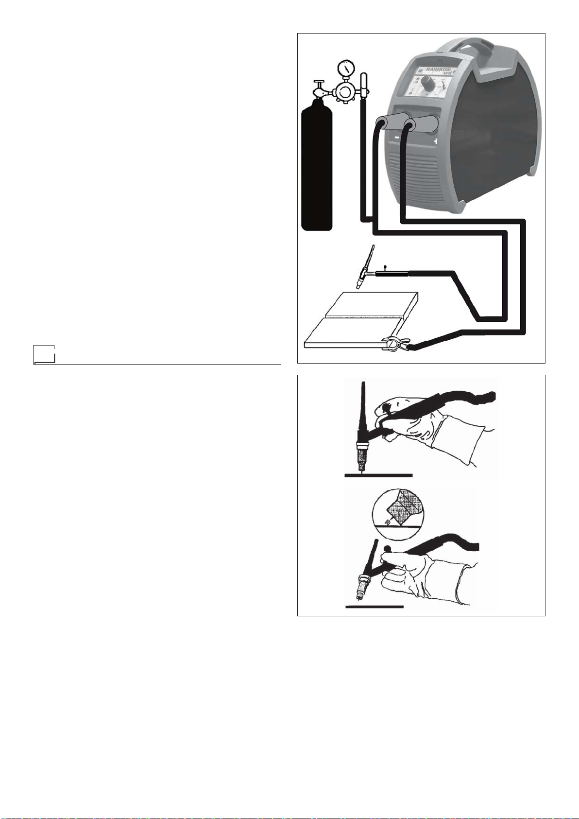
How to lift up the machine
This welding power source has a handle for picking it up and car-
rying it by hand.
NOTE: These hoisting and transportation devices conform to Eu-
ropean standards. Do not use other hoisting and transportation
systems.
Open the packaging
The system essentially consists of:
• DIX GO 1206.M C
• weld unit.
Upon receiving the system:
• Remove the welding generator and all relative accessories and
components from the packaging.
•
Check that the weld machine is in good condition, if not report
any problems immediately to the seller-distributor.
•
Make sure all ventilation grilles are open and that no foreign bod-
ies are blocking the air circulation.
Installation
The installation site for the system must be carefully chosen in or-
der to ensure its satisfactory and safe use.
The user is responsible for the installation and use of the system
in accordance with the producer’s instructions contained in this
manual.
Before installing the system the user must take into consideration
the potential electromagnetic problems in the work area. In particu-
lar, we suggest that you should avoid installing the system close to:
• Signalling, control and telephone cables.
• Radio and television transmitters and receivers.
• Computers and control and measurement instruments.
• Security and protection instruments.
Persons fitted with pace makers, hearing aids and similar equip-
ment must consult their doctor before going near a machine in
operation. The equipment’s installation environment must comply
to the protection level of the frame i.e. IP 23 S (IEC 60529 publi-
cation). The system is capable of working in environments where
working conditions are particularly hard. This system is cooled by
means of the forced circulation of air, and must therefore be placed
in such a way that the air may be easily sucked in and expelled
through the apertures made in the frame.
Connection to the electrical supply
Before connecting the welding power source to the electrical
supply, check that the machine’s plate rating corresponds to
the supply voltage and frequency and that the line switch of
the welding power source is in the “O” position.
This system has been designed for nominal voltage 230 V - 50/60
Hz. It can however work at 220 V and 240 V - 50/60 Hz without
any problem. Connection to the power supply must be carried out
using the tripolar cable supplied with the system, of which:
•
2 conducting wires are needed for connecting the machine to
the supply.
• The third, which is YELLOW GREEN in colour is used for mak-
ing the “EARTH” connection.
Connect a suitable load of normalised plug (2p + e) to the
power cable and provide for an electrical socket complete
with fuses or an automatic switch. The earth terminal must
be connected to the earth conducting wire (YELLOW-GREEN)
of the supply.
Table 2 shows the capacity values that are recommended for fus-
es in the line with delays.
NOTE 1: Any extensions to the power cable must be of a suitable
diameter, and absolutely not of a smaller diameter than the spe-
cial cable supplied with the machine.
NOTE 2: It is not advisable to plug up the welding power source
to motor-driven generators, as they are known to supply an un-
stable voltage.
Table 1
Model DIX
GO 1206.M C
Single-phase power supply 50/60 Hz V230
Mains supply: Zmax (*) Ω0,26
Power input @ I2Max kVA 11,3
Delayed fuse (I2@ 100%) A20
Power factor / cosφ 0,55 / 0,99
Maximum efficiency degree η0,74
Open circuit voltage (max) V105
Open circuit voltage (resting) V≤12
vrd - Intervention time at end of welding s≤0,3
vrd - LST LED indication
green
red V
VU2 > 35
U2≤35
Current range A5 ÷ 180
Duty cycle @ 100% (40°C) A100
Duty cycle @ 60% (40°C) A120
Duty cycle @ 20% (40°C) A180
Usable electrodes Ø mm 1,6 ÷ 4
Standards IEC 60974-1
IEC 60974-10
Insulation class IP 23 S
Protection class F
Dimensions mm 390-300-135
Weight kg 6,5
(*) Mains supply Zmax: maximum impedance value allowed for the grid
according to the EN/IEC 61000-3-11 standard.
WARNING: This equipment does not comply with EN/IEC 61000-3-12.
If it is connected to a public low voltage system, it is the responsibil-
ity of the installer or user of the equipment to ensure, by consultation
with the distribution network operator if necessary, that the equipment
may be connected.